

Page 1

© PCE Instruments
PCE-MFM 2400 Serie| series Teslameter
Bedienungsanleitung
User Manual
User manuals in various languages (français,
italiano, español, português, nederlands, türk, polski,
русский, 中文) can be found by using our
product search on: www.pce-instruments.com
Letzte Änderung / last change: 1 October 2020
v1.1
Deutsch
English
Page 2

© PCE Instruments
Deutsch
Inhaltsverzeichnis
1 Sicherheitsinformationen ..................................................................... 1
2 Spezifikationen ...................................................................................... 2
2.1 Technische Spezifikationen .............................................................................................. 2
2.2 Lieferumfang ................................................................................................ .................... 2
2.3 Optionales Zubehör .......................................................................................................... 2
3 Systembeschreibung ............................................................................ 3
3.1 Gerät ................................................................................................................................ 3
3.2 Anschlüsse ....................................................................................................................... 4
3.3 Display ................................ ................................................................ ............................. 5
3.4 Funktionstasten ................................................................................................................ 5
4 Vorbereitung .......................................................................................... 6
4.1 Stromversorgung .............................................................................................................. 6
4.2 Inbetriebnahme ................................................................................................................ 6
5 Betrieb .................................................................................................... 6
5.1 Nullpunktjustage ............................................................................................................... 6
5.2 Messen ............................................................................................................................ 6
5.3 Automatische Abschaltung ............................................................................................... 7
5.4 Anzeigefunktionen ............................................................................................................ 7
6 Garantie .................................................................................................. 8
7 Entsorgung ............................................................................................ 8
Page 3

English
Contents
1 Safety notes ........................................................................................... 9
2 Specifications ...................................................................................... 10
2.1 Technical specifications ..................................................................................................10
2.2 Delivery contents .............................................................................................................10
2.3 Optional accessories .......................................................................................................10
3 System description ............................................................................. 11
3.1 Device .............................................................................................................................11
3.2 Interfaces ........................................................................................................................12
3.3 Display ................................ ................................................................ ............................13
3.4 Function keys ..................................................................................................................13
4 Getting started ..................................................................................... 14
4.1 Power supply ..................................................................................................................14
4.2 Preparation .....................................................................................................................14
5 Operation ............................................................................................. 14
5.1 Zero point adjustment ......................................................................................................14
5.2 Measurement ................................ ................................................................ ..................14
5.3 Auto Power Off ................................................................................................................15
5.4 Display functions .............................................................................................................15
6 Contact ............................................................................................... 16
7 Disposal ............................................................................................... 16
© PCE Instruments
Page 4

© PCE Instruments
1
Deutsch
1 Sicherheitsinformationen
Bitte lesen Sie dieses Benutzer-Handbuch sorgfältig und vollständig, bevor Sie das Gerät zum ersten
Mal in Betrieb nehmen. Die Benutzung des Gerätes darf nur durch sorgfältig geschultes Personal
erfolgen. Schäden, die durch Nichtbeachtung der Hinweise in der Bedienungsanleitung entstehen,
entbehren jeder Haftung.
• Dieses Messgerät darf nur in der in dieser Bedienungsanleitung beschriebenen Art und
Weise verwendet werden. Wird das Messgerät anderweitig eingesetzt, kann es zu
gefährlichen Situationen kommen.
• Verwenden Sie das Messgerät nur, wenn die Umgebungsbedingungen (Temperatur,
Luftfeuchte, …) innerhalb der in den Spezifikationen angegebenen Grenzwerte liegen.
Setzen Sie das Gerät keinen extremen Temperaturen, direkter Sonneneinstrahlung,
extremer Luftfeuchtigkeit oder Nässe aus.
• Setzen Sie das Gerät keinen Stößen oder starken Vibrationen aus.
• Das Öffnen des Gerätegehäuses darf nur von Fachpersonal der PCE Deutschland GmbH
vorgenommen werden.
• Benutzen Sie das Messgerät nie mit nassen Händen.
• Es dürfen keine technischen Veränderungen am Gerät vorgenommen werden.
• Das Gerät sollte nur mit einem Tuch gereinigt werden. Verwenden Sie keine Scheuermittel
oder lösungsmittelhaltige Reinigungsmittel.
• Das Gerät darf nur mit dem von der PCE Deutschland GmbH angebotenen Zubehör oder
gleichwertigem Ersatz verwendet werden.
• Überprüfen Sie das Gehäuse des Messgerätes vor jedem Einsatz auf sichtbare
Beschädigungen. Sollte eine sichtbare Beschädigung auftreten, darf das Gerät nicht
eingesetzt werden.
• Das Messgerät darf nicht in einer explosionsfähigen Atmosphäre eingesetzt werden.
• Der in den Spezifikationen angegebene Messbereich darf unter keinen Umständen
überschritten werden.
• Wenn die Sicherheitshinweise nicht beachtet werden, kann es zur Beschädigung des
Gerätes und zu Verletzungen des Bedieners kommen.
• Es ist darauf zu achten, dass der Hall-Sensor keinen starken Kräften oder Drücken
ausgesetzt und die Sensorspitze nicht verbogen wird. Sonst können Messabweichungen
und Kennlinienverschiebungen entstehen.
Für Druckfehler und inhaltliche Irrtümer in dieser Anleitung übernehmen wir keine Haftung.
Wir weisen ausdrücklich auf unsere allgemeinen Gewährleistungsbedingungen hin, die Sie in unseren
Allgemeinen Geschäftsbedingungen finden.
Bei Fragen kontaktieren Sie bitte die PCE Deutschland GmbH. Die Kontaktdaten finden Sie am Ende
dieser Anleitung.
Page 5
© PCE Instruments
2
Deutsch
2 Spezifikationen
2.1 Technische Spezifikationen
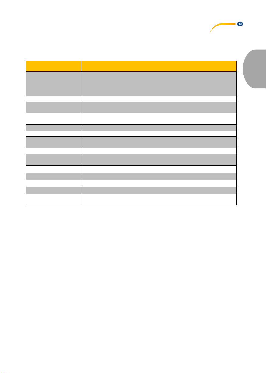
Spezifikationen des Messgeräts PCE-MFM 2400 und PCE-MFM 2400+
Spezifikation
Erläuterung
Messbereich
0 … 200 mT
200 … 2400 mT
0 … 2000 Gs
2000 … 24000 Gs
Genauigkeit
±1 % v. Mw.
Auflösung
0,01 mT
0,1 Gs
Messrichtung
transversal (PCE-MFM 2400)
axial (PCE-MFM 2400+)
Magnetfeld
statisch (DC)
Einheit
mT, Gs
Stromversorgung
1 x 9 V (DC) Batterieblock
im Ruhezustand automatische Abschaltung nach 5 Minuten
Modus
Haltemodus, Messmodus
Display
Hintergrundbeleuchtung
digitale 4-stellige Wertanzeige
Betriebstemperatur
0 …+50 °C
Lagertemperatur
-20 …+50 °C
Abmessungen
185 x 97 x 40 mm
Gewicht
310 g
Sensoren
Hall-Sensor transversal, Kabellänge ca. 1 m
Hall-Sensor axial, Kabellänge ca. 2 m
2.2 Lieferumfang
1 x Teslameter PCE-MFM 2400 oder Teslameter PCE-MFM 2400+
1 x Hall-Sensor
1 x Bedienungsanleitung
1 x Servicetasche
1 x 9V Batterieblock
2.3 Optionales Zubehör
Instrumentenkoffer
ISO-Kalibrierzertifikat
Page 6
© PCE Instruments
3
Deutsch
3 Systembeschreibung
3.1 Gerät
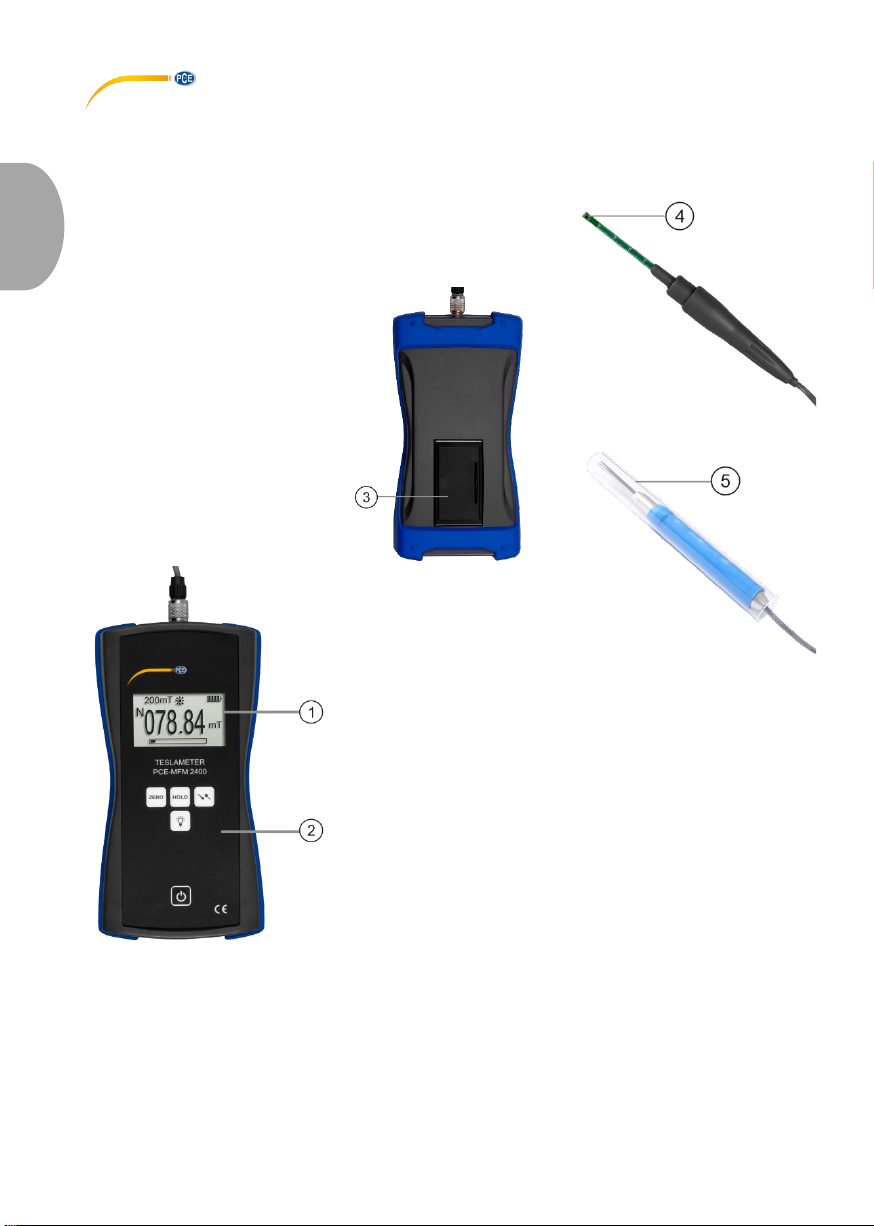
1. Display 4. Transversaler Sensor
2. Folientastatur 5. Axialer Sensor
3. Batteriefach
Page 7

© PCE Instruments
4
Deutsch
3.2 Anschlüsse
1. Anschlussbuchse
Page 8
© PCE Instruments
5
Deutsch
3.3 Display
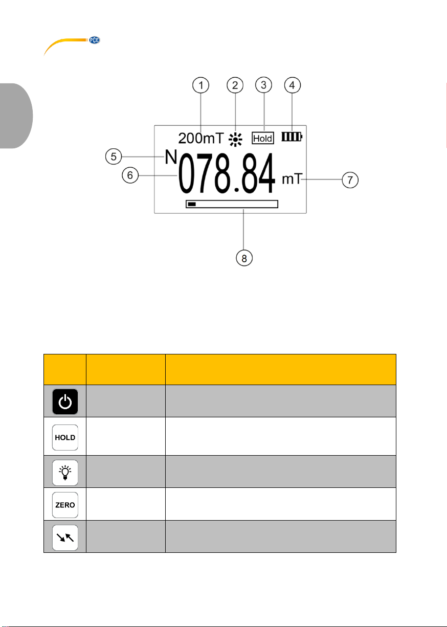
1. Aktueller Messbereich 5. Magnetische Polarität
2. Hintergrundbeleuchtung 6. Aktueller Messwert
3. Haltemodus 7. Einheit (mT/Gs)
4. Batteriestatus 8. Prozentsatzanzeige des Messbereichs
3.4 Funktionstasten
Taste
Bezeichnung
Funktion
Ein/Aus
Gerät ein- und ausschalten
HOLD
Durch Drücken der Taste wird der aktuell gemessene
Maximalmesswert auf dem Display beibehalten. Im Display
wird „Hold“ angezeigt. Bei erneutem Drücken wird die
Messung normal fortgesetzt und das Symbol verschwindet.
Licht
Hintergrundbeleuchtung ein- und ausschalten
ZERO
Nullpunktjustage
Einheit
Einheit zwischen mT und Gs umstellen (1 mT = 10 Gs)
Page 9
© PCE Instruments
6
Deutsch
4 Vorbereitung
4.1 Stromversorgung
Zur Stromversorgung wird eine 9V Blockbatterie benötigt. Bevor Sie diese tauschen; schalten Sie das
Gerät aus. Das Batteriefach befindet sich auf der Rückseite des Gerätes. Lösen Sie die Abdeckung,
legen Sie die Batterie wie gekennzeichnet ein und verschließen Sie das Batteriefach wieder.
4.2 Inbetriebnahme
Um das Gerät zu starten, drücken Sie , bis das Display reagiert. Das Messgerät zeigt nach dem
Laden den Messbildschirm an. Zum Ausschalten drücken Sie . Schrauben Sie den im
Lieferumfang enthaltenen Hall-Sensor an die Anschlussbuchse des Geräts an. Achten Sie dabei auf
die korrekte Positionierung des Steckers. Die Messspitze mit Hall-Sensors befindet sich unter der
Abdeckkappe.
5 Betrieb
5.1 Nullpunktjustage
Vor jeder Messung sollte das Messgerät auf Null justiert werden. Halten Sie dazu die Messspitze ohne
Abdeckung in die Luft oder nutzen sie eine Nullfeldkammer. Es dürfen keine magnetischen Felder
oder elektromagnetischen Störungen in der Umgebung vorhanden sein. Wenn der Messwert ungleich
0,0 mT/ Gs ist, drücken Sie die „ZERO“ Taste . Das Gerät wird justiert und sollte nun 0,0 mT/ Gs
anzeigen.
5.2 Messen
Vor der Messung sollte der Sensor auf Umgebungstemperatur erwärmt werden. Zur
Messwertaufnahme müssen Sie die Abdeckung abnehmen und die Spitze (Hall-Sensor) in der Mitte
des zu messenden Magnetfeldes platzieren. Je weiter der Sensor aus der Mitte des Magnetfeldes
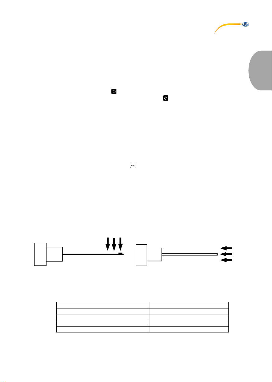
platziert ist, desto kleiner ist die magnetische Flussdichte. Zudem muss der transversale Sensor, wie
in der Abbildung zu sehen, senkrecht zum Flussvektor stehen. Bei dem axialen Sensor müssen die
Flussvektoren axial zur Messspitze zeigen. Warten Sie einen Moment, bis sich der Messwert
stabilisiert hat. Wenn das Messgerät „Over Range“ anzeigt, liegt der Messwert außerhalb des
Messbereichs.
Orientierung: transversaler Sensor Orientierung: axialer Sensor
Die maximale magnetische Flussdichte wird gemessen, wenn der Flussvektor (Pfeil) senkrecht zur
Sensorebene steht. Die Tabelle zeigt die Messabweichung nach dem Winkel zwischen dem
Flussvektor und der Sensorebene.
Winkel des Sensors zum Flussvektor
Prozentuale Abweichung
10 °
2,5 %
20 °
7 %
30 °
15,2 %
45 °
30,3 %
Page 10

© PCE Instruments
7
Deutsch
5.3 Automatische Abschaltung
Wenn 5 Minuten lang keine Eingabe erfolgt, schaltet sich das Messgerät automatisch aus und spart
so Energie. Wenn Sie das Gerät wieder nutzen möchten, müssen Sie es mit wieder einschalten.
5.4 Anzeigefunktionen
Halten
Um den jeweiligen Maximalwert korrekt ablesen zu können, hat das Messgerät eine Haltefunktion.
Dazu müssen Sie die „HOLD“ Taste drücken. Es erscheint, wie in der Displaybeschreibung zu
sehen, ein „Hold“ Zeichen rechts oben im Display. Das Messgerät zeigt nun immer den Betrag des
gemessenen Maximalwerts im negativen und im positiven Bereich an.
Polarität
Das Messgerät kann die Einfallrichtung der Magnetfeldlinien anzeigen. Wenn die Magnetfeldlinien auf
die Vorderseite des Hall-Sensors fallen, zeigt das Messgerät einen positiven Wert mit einem „N“ an.
Wenn die Magnetfeldlinien auf die Rückseite des Hall-Sensors fallen, wird ein negativer Messwert
angezeigt und hat ein vorgestelltes „S“.
Messbereich
Das Messgerät kann zwischen zwei Messbereichen automatisch umschalten. Wenn sich der aktuelle
Wert im Bereich 0 … 200 mT befindet, schaltet sich das Messgerät in den 200 mT Messbereich. Bei
Überschreiten der 200 mT schaltet das Gerät automatisch auf 2000 mT um. Der aktuelle Bereich wird
im Display angezeigt. In jedem Bereich wird über die Prozentleiste der aktuell ausgeschöpfte
Messbereich als Prozentsatz angezeigt. Die Prozentleiste hat insgesamt 10 Kästen mit je 10 %iger
Gewichtung. Wenn der Messwert größer als 2400 mT und die Leiste voll ist, zeigt das Gerät „Over
Range“ an.
Page 11

© PCE Instruments
8
Deutsch
6 Garantie
Unsere Garantiebedingungen können Sie in unseren Allgemeinen Geschäftsbedingungen nachlesen,
die Sie hier finden: https://www.pce-instruments.com/deutsch/agb.
7 Entsorgung
HINWEIS nach der Batterieverordnung (BattV)
Batterien dürfen nicht in den Hausmüll gegeben werden: Der Endverbraucher ist zur Rückgabe
gesetzlich verpflichtet. Gebrauchte Batterien können unter anderem bei eingerichteten
Rücknahmestellen oder bei der PCE Deutschland GmbH zurückgegeben werden.
Annahmestelle nach BattV:
PCE Deutschland GmbH
Im Langel 4
59872 Meschede
Zur Umsetzung der ElektroG (Rücknahme und Entsorgung von Elektro- und Elektronikaltgeräten)
nehmen wir unsere Geräte zurück. Sie werden entweder bei uns wiederverwertet oder über ein
Recyclingunternehmen nach gesetzlicher Vorgabe entsorgt. Alternativ können Sie Ihre Altgeräte auch
an dafür vorgesehenen Sammelstellen abgeben.
WEEE-Reg.-Nr.DE69278128
Page 12

© PCE Instruments
9
English
1 Safety notes
Please read this manual carefully and completely before you use the device for the first time. The
device may only be used by qualified personnel and repaired by PCE Instruments personnel. Damage
or injuries caused by non-observance of the manual are excluded from our liability and not covered by
our warranty.
• The device must only be used as described in this instruction manual. If used otherwise, this
can cause dangerous situations for the user and damage to the meter.
• The instrument may only be used if the environmental conditions (temperature, relative
humidity, …) are within the ranges stated in the technical specifications. Do not expose the
device to extreme temperatures, direct sunlight, extreme humidity or moisture.
• Do not expose the device to shocks or strong vibrations.
• The case should only be opened by qualified PCE Instruments personnel.
• Never use the instrument when your hands are wet.
• You must not make any technical changes to the device.
• The appliance should only be cleaned with a damp cloth. Use only pH-neutral cleaner, no
abrasives or solvents.
• The device must only be used with accessories from PCE Instruments or equivalent.
• Before each use, inspect the case for visible damage. If any damage is visible, do not use
the device.
• Do not use the instrument in explosive atmospheres.
• The measurement range as stated in the specifications must not be exceeded under any
circumstances.
• Non-observance of the safety notes can cause damage to the device and injuries to the
user.
• Make sure the Hall sensor is not exposed to strong force or pressure and that the sensor tip
is not bent as otherwise measuring deviations and offsets of the characteristic curve may
occur.
We do not assume liability for printing errors or any other mistakes in this manual.
We expressly point to our general guarantee terms which can be found in our general terms of
business.
If you have any questions please contact PCE Instruments. The contact details can be found at the
end of this manual.
Page 13
© PCE Instruments
10
English
2 Specifications
2.1 Technical specifications
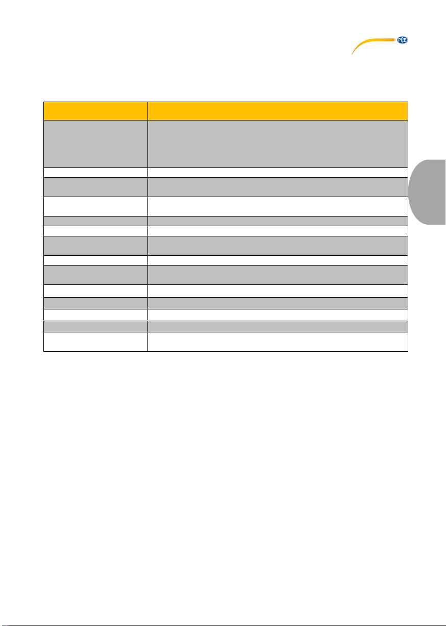
Specifications of the meter PCE-MFM 2400 and PCE-MFM 2400+
Specification
Description
Measurement range
0 … 200 mT
200 … 2400 mT
0 … 2000 Gs
2000 … 24000 Gs
Accuracy
±1 % of rdg.
Resolution
0.01 mT
0.1 Gs
Measuring direction
transversal (PCE-MFM 2400)
axial (PCE-MFM 2400+)
Magnetic field
static (DC)
Unit
mT, Gs
Power supply
1 x 9 V (DC) battery block
automatic shutdown after 5 minutes of inactivity
Mode
HOLD mode, measuring mode
Display
backlight
digital 4-digit value display
Operating temperature
0 …+50 °C
Storage temperature
-20 …+50 °C
Dimensions
185 x 97 x 40 mm
Weight
310 g
Sensors
Hall sensor transversal, cable length approx. 1 m
Hall sensor axial, cable length approx. 2 m
2.2 Delivery contents
1 x Teslameter PCE-MFM 2400 or Teslameter PCE-MFM 2400+
1 x Hall sensor
1 x user manual
1 x service bag
1 x 9 V battery block
2.3 Optional accessories
Carrying case
ISO calibration certificate
Page 14
© PCE Instruments
11
English
3 System description
3.1 Device
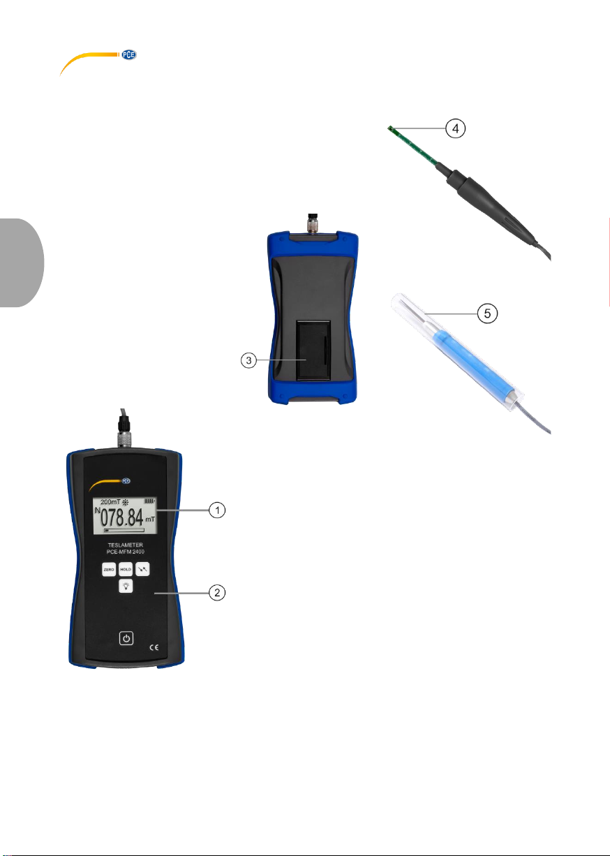
1. Display 4. Transversal sensor
2. Membrane keypad 5. Axial sensor
3. Battery compartment
Page 15

© PCE Instruments
12
English
3.2 Interfaces
1. Connection socket
Page 16
© PCE Instruments
13
English
3.3 Display
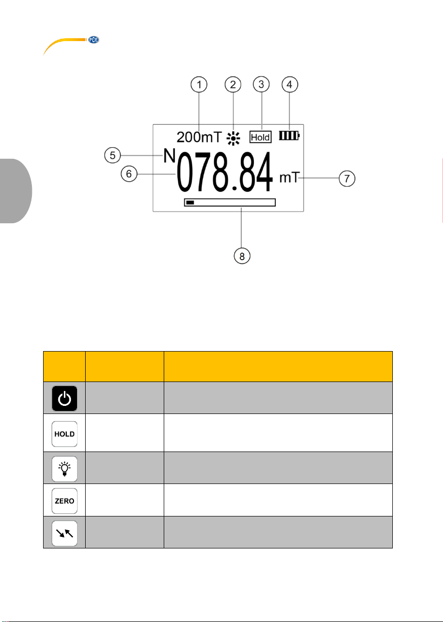
1. Current measurement range 5. Magnetic polarity
2. Backlight 6. Percentage bar
3. HOLD mode 7. Unit (mT/Gs)
4. Current reading
3.4 Function keys
Key
Description
Function
On/off
Turn meter on/off
HOLD
By pressing this key, the measured maximum value will be
held in the display. “Hold“ will be displayed. When the key is
pressed again, the measurement will be continued normally
and the ”Hold“ icon disappears.
Light
Turn backlight on/off
ZERO
Zero point adjustment
Unit
Switch unit to mT or Gs (1 mT = 10 Gs)
Page 17

© PCE Instruments
14
English
4 Getting started
4.1 Power supply
For power supply, a 9 V block battery is required. Before replacing these, turn off the meter. The battery
compartment is located at the rear side of the meter. Loosen the cover and insert the battery as
marked. Then close the battery compartment cover.
4.2 Preparation
To start the meter, press until the display reacts. After charging the meter, the measuring screen
will be visible. To turn off the meter, press again. Screw the included Hall sensor into the
connection socket of the meter. Make sure that the plug is in the right position. The measuring tip
with Hall sensor is below the cover.
5 Operation
5.1 Zero point adjustment
A zero point adjustment should be carried out before each measurement. To do so, remove the cover
and raise the measuring tip up in the air or use a zero field chamber. Make sure no magnetic fields or
electromagnetic interference occur in the environment. If the reading is not 0.0 mT/Gs, press the ZERO
key . The meter will be adjusted and should then display 0.0 mT/Gs.
5.2 Measurement
Before making a measurement, make sure the sensor reaches the environmental temperature. The
cover must be removed to be able to make a measurement. Place the tip (Hall sensor) in the centre
of the magnetic field you wish to measure. The farther the sensor is away from the centre of the
magnetic field, the lower the magnetic flux density will be. As you can see in the picture below, the
transversal sensor must be placed vertically to the flux vector. If you are using the axial sensor, the
flux vectors must be axial to the measuring tip. Allow some time for the reading to stabilise. If the
display shows “Over Range“, the measured value is outside the measurement range.
Orientation of transversal sensor Orientation of axial sensor
The maximum magnetic flux density is measured when the flux vector (see arrows) is vertical to the
sensor plane. The following chart shows the measuring deviation in line with the angle between the
flux vector and the sensor plane.
Sensor’s angle to the flux vector
Deviation in per cent
10 °
2.5 %
20 °
7 %
30 °
15.2 %
45 °
30.3 %
Page 18

© PCE Instruments
15
English
5.3 Auto Power Off
When no entries have been made for 5 minutes, the meter will turn off automatically to save energy.
If you wish to use the meter again after Auto Power Off, press to turn it back on.
5.4 Display functions
Hold
To enable the user to read the maximum value correctly, the meter has a Hold function. To activate
this function, press the “HOLD” key . As you can see in the display description above, a “Hold“ icon
will appear in the upper right corner of the display. The meter will now always display the absolute
value of the measured positive and negative maximum value.
Polarity
The meter can display the direction of incidence of the magnetic field lines. If the magnetic field lines
touch the front side of the Hall sensor, the meter will display a positive value along with an ”N”. On the
other hand, if the magnetic field lines touch the rear side of the Hall sensor, the reading will be negative
and displayed with an ”S“.
Measurement range
The meter can automatically switch between two measurement ranges. When the current reading is
within the range 0 … 200 mT, it will apply the 200 mT measurement range. When 200 mT are
exceeded, the meter will automatically switch to 2000 mT. The current measurement range is shown
in the display. In both ranges, the percentage bar will show the percentage of the current reading from
the measurement range. The percentage bar has 10 boxes which stand for a portion of 10 % each. If
the reading is higher than 2400 mT and the percentage bar is full, the meter will display ”Over Range“.
Page 19

English
6 Contact
If you have any questions, suggestions or technical problems, please do not hesitate to contact us.
You will find the relevant contact information at the end of this user manual.
7 Disposal
For the disposal of batteries in the EU, the 2006/66/EC directive of the European Parliament applies.
Due to the contained pollutants, batteries must not be disposed of as household waste. They must be
given to collection points designed for that purpose.
In order to comply with the EU directive 2012/19/EU we take our devices back. We either re-use them
or give them to a recycling company which disposes of the devices in line with law.
For countries outside the EU, batteries and devices should be disposed of in accordance with your
local waste regulations.
If you have any questions, please contact PCE Instruments.
© PCE Instruments
16
Page 20

© PCE Instruments
17
English
PCE Instruments contact information
Germany France Spain
PCE Deutschland GmbH PCE Instruments France EURL PCE Ibérica S.L.
Im Langel 4 23, rue de Strasbourg Calle Mayor, 53
D-59872 Meschede 67250 Soultz-Sous-Forets 02500 Tobarra (Albacete)
Deutschland France España
Tel.: +49 (0) 2903 976 99 0 Téléphone: +33 (0) 972 3537 17 Tel. : +34 967 543 548
Fax: +49 (0) 2903 976 99 29 Numéro de fax: +33 (0) 972 3537 18 Fax: +34 967 543 542
[email protected] [email protected] [email protected]
www.pce-instruments.com/deutsch www.pce-instruments.com/french www.pce-instruments.com/espanol
United Kingdom Italy Turkey
PCE Instruments UK Ltd PCE Italia s.r.l. PCE Teknik Cihazları Ltd.Şti.
Unit 11 Southpoint Business Park Via Pesciatina 878 / B-Interno 6 Halkalı Merkez Mah.
Ensign Way, Southampton 55010 Loc. Gragnano Pehlivan Sok. No.6/C
Hampshire Capannori (Lucca) 34303 Küçükçekmece - İstanbul
United Kingdom, SO31 4RF Italia Türkiye
Tel: +44 (0) 2380 98703 0 Telefono: +39 0583 975 114 Tel: 0212 471 11 47
Fax: +44 (0) 2380 98703 9 Fax: +39 0583 974 824 Faks: 0212 705 53 93
[email protected] [email protected] [email protected]
www.pce-instruments.com/english www.pce-instruments.com/italiano www.pce-instruments.com/turkish
The Netherlands China Hong Kong
PCE Brookhuis B.V. PCE (Beijing) Technology Co., Limited PCE Instruments HK Ltd.
Institutenweg 15 1519 Room, 6 Building Unit J, 21/F., COS Centre
7521 PH Enschede Zhong Ang Times Plaza 56 Tsun Yip Street
Nederland No. 9 Mentougou Road, Tou Gou District Kwun Tong
Telefoon: +31 (0)53 737 01 92 102300 Beijing, China Kowloon, Hong Kong
[email protected] Tel: +86 (10) 8893 9660 Tel: +852-301-84912
www.pce-instruments.com/dutch [email protected] [email protected]
www.pce-instruments.cn www.pce-instruments.cn
United States of America
PCE Americas Inc.
1201 Jupiter Park Drive, Suite 8
Jupiter / Palm Beach
33458 FL
USA
Tel: +1 (561) 320-9162
Fax: +1 (561) 320-9176
[email protected]
www.pce-instruments.com/us
Page 21

© PCE Instruments
Page 22

© PCE Instruments
Page 23

© PCE Instruments
Page 24

© PCE Instruments
User manuals in various languages (français, italiano, español,
português, nederlands, türk, polski, русский, 中文) can be found by
using our product search on: www.pce-instruments.com
Specifications are subject to change without notice.
 Loading...