

Page 1
PC Software PCE-322A
Bedienungsanleitung
User Manual
User manuals in various languages (français,
italiano, español, português, nederlands, türk, polski,
русский, 中文) can be found by using our
product search on: www.pce-instruments.com
Letzte Änderung / last change: 13 October 2017
v1.2
Deutsch
English
Page 2

Deutsch
Inhaltsverzeichnis
1 Sicherheitsinformationen ..................................................................... 1
2 Systemvoraussetzungen ...................................................................... 1
3 Installation ............................................................................................. 1
4 Beschreibung der Oberfläche .............................................................. 2
5 Bedeutung der einzelnen Symbole der Symbolleiste ....................... 3
6 Bedienung .............................................................................................. 5
6.1 Die erste Benutzung der Software .................................................................................... 5
6.2 Verbindung zum "PCE-322A" herstellen ........................................................................... 5
6.3 Verbindung zum "PCE-322A" trennen .............................................................................. 5
6.4 Liste der Messreihen ........................................................................................................ 6
6.5 Numerische Anzeige ........................................................................................................ 6
6.6 Statistische Daten ............................................................................................................ 7
6.7 Grafische Darstellung ....................................................................................................... 7
6.8 Durchführung einer Messung ........................................................................................... 9
6.9 Daten-Import ................................................................................................ .................... 9
6.10 Export von Messreihen ..................................................................................................... 9
6.11 Laden und Speichern von Messreihen ............................................................................. 9
© PCE Instruments
Page 3

English
Contents
1 Safety notes ......................................................................................... 10
2 System requirements ......................................................................... 10
3 Installation ........................................................................................... 10
4 Operation ............................................................................................. 11
4.1 Description of the user interface ......................................................................................11
5 Meaning of the Individual Icons on the Toolbar .............................. 12
6 Operation ............................................................................................. 14
6.1 The first use of the software ............................................................................................14
6.2 Connect to the "PCE-322A" .............................................................................................14
6.3 Disconnect from the “PCE-322A” ....................................................................................14
6.4 List of measurement series .............................................................................................15
6.5 Numerical display ............................................................................................................15
6.6 Statistical data .................................................................................................................16
6.7 Graphical representation .................................................................................................16
6.8 Performing the measurement ..........................................................................................18
6.9 Data import .....................................................................................................................18
6.10 Export of series of measurements ...................................................................................18
6.11 Loading and saving series of measurements ...................................................................18
© PCE Instruments
Page 4

Deutsch
1 Sicherheitsinformationen
Machen Sie sich mit der Bedienung des Messgerätes vertraut, bevor Sie es in Verbindung mit
der Software verwenden. Nutzen Sie dazu die Bedienungsanleitung, welche Ihrem PCE-Gerät
beiliegt. Sämtliche Sicherheitshinweise aus der Bedienungsanleitung des Messgerätes gelten
auch bei seiner Verwendung mit der PC-Software.
Die Benutzung des Gerätes und der Software darf nur durch sorgfältig geschultes Personal
erfolgen. Schäden, die durch Nichtbeachtung der Hinweise in den jeweiligen
Bedienungsanleitungen entstehen, entbehren jeder Haftung.
Für Druckfehler und inhaltliche Irrtümer in dieser Anleitung übernehmen wir keine Haftung.
Wir weisen ausdrücklich auf unsere allgemeinen Gewährleistungsbedingungen hin, die Sie in
unseren Allgemeinen Geschäftsbedingungen finden.
Bei Fragen kontaktieren Sie bitte die PCE Deutschland GmbH. Die Kontaktdaten finden Sie am
Ende dieser Anleitung.
2 Systemvoraussetzungen
Betriebssystem ab Windows XP SP3
USB-Port (2.0 oder höher).
Ein installiertes .NET-Framework 4.0
Eine Mindestauflösung von 800x600 Pixel
Optional: ein Drucker
Prozessor mit 1 GHz
4 GB RAM Arbeitsspeicher empfohlen
CD-ROM Laufwerk
3 Installation
Bitte führen Sie die "Setup PCE-322A.exe" aus und folgen Sie den Anweisungen des Setups.
© PCE Instruments
1
Page 5
Deutsch
4 Beschreibung der Oberfläche
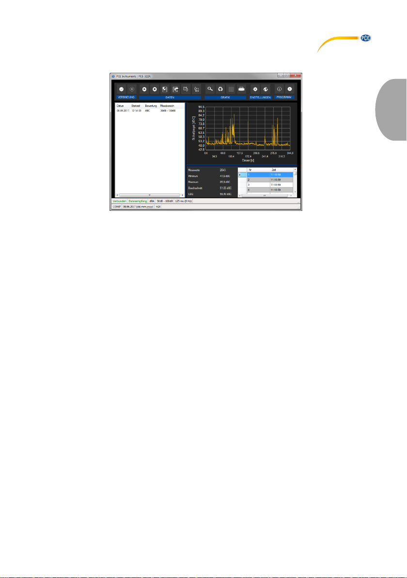
Das Hauptfenster setzt sich aus mehreren Bereichen zusammen:
Unterhalb der Titelleiste befindet sich eine Symbolleiste deren Symbole funktional gruppiert
sind.
Unter dieser Symbolleiste befindet sich im linken Teil des Fensters eine Auflistung von
Messreihen.
Der rechte Teil des Fensters gliedert sich in einen oberen und einen unteren Teil.
Im oberen Teil ist der Bereich zur grafischen Anzeige der Messwerte.
Der untere Teil hingegen bietet zum Einen eine Übersicht von statistischen Daten und
außerdem eine tabellarische Auflistung der Messwerte.
Am unteren Rand des Hauptfensters befinden sich zwei Statusleisten ("Statusbars") mit
wichtigen Informationen direkt übereinander.
Die untere der beiden zeigt die statischen Einstellungen des Programms, die über einen
Einstellungs-Dialog festgelegt werden können (COM-Port, Datums- und Zeitformat).
Die obere Statusleiste zeigt die dynamischen Einstellungen des "PCE-322A", die direkt von
dem verbundenen Gerät abgerufen werden.
© PCE Instruments
2
Page 6

Deutsch
5 Bedeutung der einzelnen Symbole der Symbolleiste
Gruppe "Verbindung"
Verbindung mit dem "PCE-322A" herstellen
Verbindung mit dem "PCE-322A" trennen
Gruppe "Daten"
Eine Messung starten
Eine Messung beenden
Messreihen vom "PCE-322A" importieren
Messreihen exportieren
Laden einer Messreihe aus einer Datei
Speichern einer Messreihe in eine Datei
Gruppe „Grafik“
Vergrößerung eines Grafikbereichs ("Zoomen") bzw.
Bewegen der vergrößerten Grafik
Wiederherstellung der originalen Grafik
Hintergrund und Darstellung der Grafik ändern
Drucken der aktuell sichtbaren Grafik
© PCE Instruments
3
Page 7
Deutsch
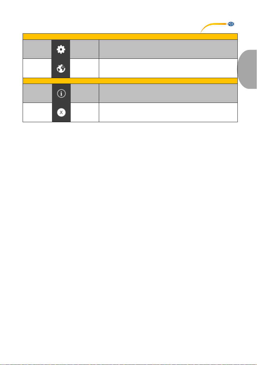
Gruppe "Einstellungen"
Den Einstellungs-Dialog aufrufen
Auswahl einer vom Programm unterstützten Sprache
Gruppe "Programm"
Einen Informations-Dialog anzeigen
Das Programm beenden
© PCE Instruments
4
Page 8
Deutsch
6 Bedienung
6.1 Die erste Benutzung der Software
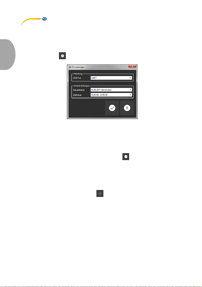
Bevor das "PCE-322A" mit der Software zusammenarbeiten kann, muss einmalig der
zugewiesene COM-Port in der Software eingestellt werden. Dieser kann mit Hilfe des
"Einstellungs-Dialogs" festgelegt werden.
Zusätzlich zu den Verbindungsdaten können hier noch weitere Einstellungen zum Datums- und
Zeitformat vorgenommen werden.
6.2 Verbindung zum "PCE-322A" herstellen
Nachdem die gewünschten Einstellungen vorgenommen und der Einstellungs-Dialog mit einem
Klick auf die "Übernehmen"-Schaltfläche geschlossen wurde, kann die Verbindung zu dem
"PCE-322A" durch Anklicken des entsprechenden Symbols hergestellt werden.
Konnte die Verbindung erfolgreich hergestellt werden, so wird in der Statusleiste für die
dynamischen Daten der Begriff "Verbunden" in grüner Farbe dargestellt.
Wenn jedoch keine Verbindung hergestellt ist, so wird dort der Begriff "Getrennt" in roter Farbe
dargestellt.
6.3 Verbindung zum "PCE-322A" trennen
Mit einem Klick auf das betreffende Symbol kann eine aktive Verbindung zum "PCE-322A"
wieder getrennt werden.
Auch ein Beenden der Software bei aktiver Verbindung trennt diese Verbindung ebenfalls.
© PCE Instruments
5
Page 9
Deutsch
6.4 Liste der Messreihen
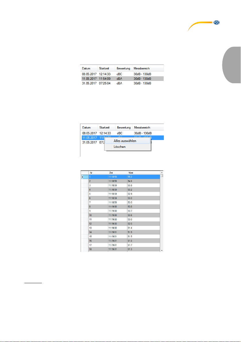
Im linken Bereich des Hauptfensters werden alle Messreihen aufgelistet, die sich zur Zeit im
Speicher des PCs befinden Jede Messreihe wird in der Liste mit dem Datum der Erstellung und
der Startzeit der Messung, der gewählten Bewertung (dBA / dBC) und dem Messbereich
dargestellt.
Je nach Auswahl einer dieser Messreihen werden die Grafik, die Tabelle und auch die
statistischen Daten aktualisiert.
Ein Klick mit der rechten Maustaste gestattet es, alle Messreihen auszuwählen oder auch eine
oder mehrere markierte Messreihen zu löschen.
6.5 Numerische Anzeige
Im unteren Bereich des Hauptfensters werden alle Messwerte tabellarisch dargestellt.
Die Tabelle kann spaltenweise sortiert werden, indem auf die jeweilige Spaltenüberschrift
("Nr", "Zeit" oder "Wert") geklickt wird.
Hinweis:
Diese Daten stammen direkt aus dem "PCE-322A"; die Uhrzeit kann also von der PC-Zeit
abweichen.
© PCE Instruments
6
Page 10
Deutsch
6.6 Statistische Daten
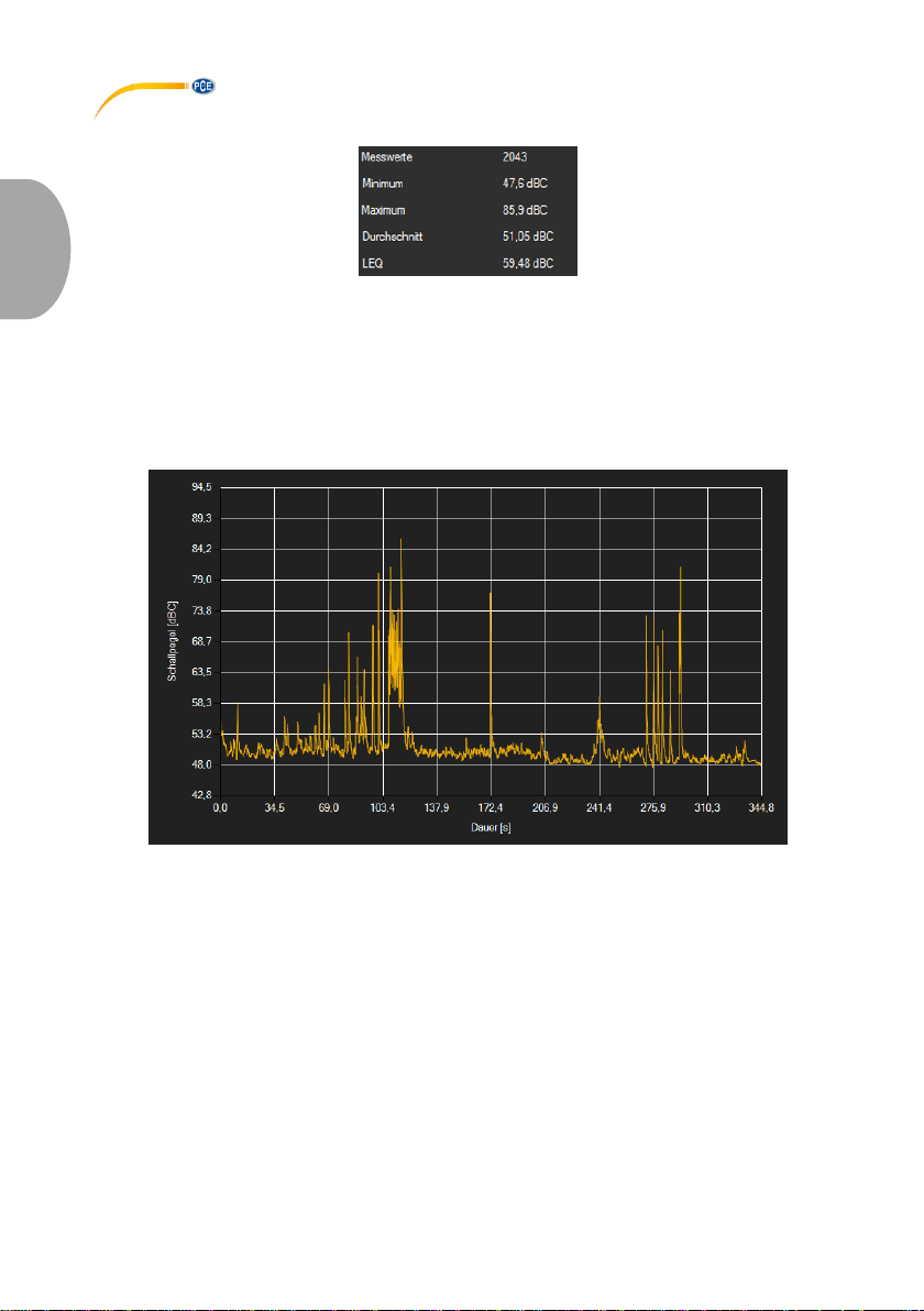
Die Statistik beinhaltet die Anzahl der gemessenen Punkte, den kleinsten und größten
gemessenen Schallpegel, den durchschnittlichen Wert und den berechneten LEQ-Wert
("Äquivalenter Dauerschallpegel", energie-äquivalente Mittelung nach DIN 45 641).
6.7 Grafische Darstellung
In dem Bereich der grafischen Auswertung wird die gewählte Bewertung (dBA / dBC) auf der yAchse und der zeitliche Verlauf (in Sekunden) auf der x-Achse abgebildet.
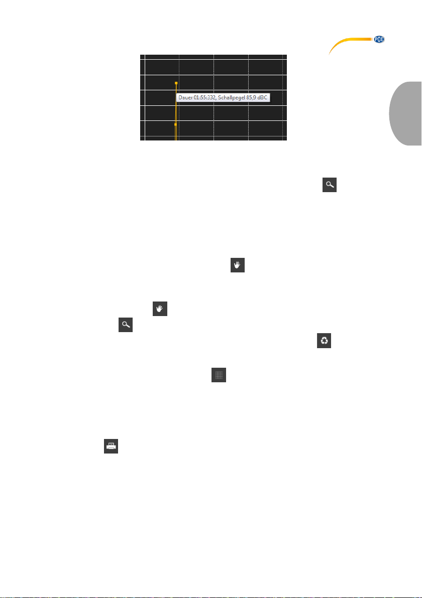
Ein Führen des Mauszeigers auf einen Punkt der dargestellten Linie sorgt nach kurzer Zeit für
das Anzeigen eines kleinen Informationsfensters mit den Daten (Zeit und Einheit) des aktuell
ausgewählten Messwerts.
© PCE Instruments
7
Page 11
Deutsch
Die dargestellte Grafik kann auch in einem frei wählbaren Teilbereich vergrößert dargestellt
werden.
Hierzu muss das entsprechende Symbol in der Symbolleiste ("Vergrößerung eines
Grafikbereichs ("Zoomen") bzw. Bewegen der vergrößerten Grafik") eine Lupe darstellen.
Dann kann bei gedrückt gehaltener Maustaste ein Rechteck über einen Bereich der Grafik
gezogen werden. Sobald die Maustaste losgelassen wird, erscheint der ausgewählte Bereich
als neue Grafik.
Sobald mindestens einmal eine Vergrößerung vorgenommen wird, kann per Klick auf das
Symbol ("Vergrößerung eines Grafikbereichs ("Zoomen") bzw. Bewegen der vergrößerten
Grafik") mit der Lupe aus dem Vergrößerungs-Modus in den Verschiebe-Modus umgeschaltet
werden. Dieser Modus wird durch das Hand-Symbol dargestellt.
Wird nun die Maus über den Grafikbereich gebracht und dann die linke Maustaste gedrückt, so
kann der abgebildete Teilausschnitt mit gehaltener Maustaste verschoben werden.
Ein erneuter Klick auf das Symbol wechselt wieder in den Vergrößerungs-Modus,
erkennbar durch das Symbol.
Die originale Grafik kann jederzeit wieder hergestellt werden, indem auf das Symbol neben
der Lupe bzw. Hand geklickt wird.
Über das rechts daneben befindliche Symbol kann der Hintergrund der Grafik und auch
deren Darstellung geändert werden. Ein Klick auf das Symbol wirkt hierbei wie ein Umschalter:
Ein einfacher Klick stellt den Hintergrund feiner aufgeteilt und die Grafik selbst mit zusätzlich
dargestellten Punkten dar. Ein weiterer Klick auf das Symbol wechselt wieder zur
Standardansicht.
Die aktuell angezeigte Grafik kann auch ausgedruckt werden.
Ein Klick auf das Symbol öffnet den bekannten "Drucken"-Dialog.
© PCE Instruments
8
Page 12
Deutsch
6.8 Durchführung einer Messung
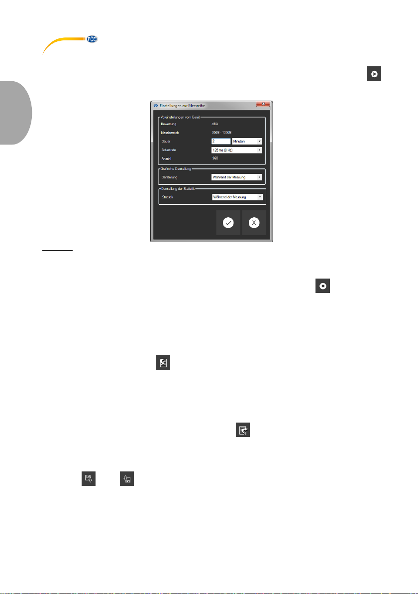
Wenn eine aktive Verbindung zum "PCE-322A" besteht, so kann mit einem Klick auf das
Symbol eine neue Messung gestartet werden.
Hinweis:
Weder die Bewertung noch der Messbereich lassen sich über die Software einstellen.
Sie werden direkt aus den Einstellungen des "PCE-322A" übernommen.
Eine laufende Messung kann auch vorzeitig manuell mit einem Klick auf das Symbol in der
Symbolleiste beendet werden.
6.9 Daten-Import
Der interne Gerätespeicher kann mit der Software ausgelesen und somit die mobil
aufgenommenen Messreihen über einen Import zur Verfügung gestellt werden.
Hierzu genügt ein Klick auf das Symbol in der Symbolleiste. Daraufhin werden Sie gefragt,
ob Sie die Messreihen aus dem Gerät tatsächlich importieren möchten. Dies kann je nach
Umfang einige Minuten dauern. Der Datenimport kann nun per Klick auf die "OK"-Schaltfläche
gestartet oder per Klick auf die "Abbrechen"-Schaltfläche abgebrochen werden.
6.10 Export von Messreihen
Messreihen können auch exportiert werden. Über das Symbol in der Symbolleiste kann der
komplette Inhalt einer einzelnen Messreihe im CSV-Format exportiert werden.
6.11 Laden und Speichern von Messreihen
Über das bzw. Symbol in der Symbolleiste kann eine Messreihe geladen und
gespeichert werden.
© PCE Instruments
9
Page 13

English
1 Safety notes
Acquaint yourself with the operation of the measuring device before using it in combination with
the PC software. For this purpose, use the instruction manual which comes with your PCE
product. All safety notes from the device’s manual have to be observed as well when the device
is used with this software.
The device and the software may only be used by qualified personnel. Damage or injuries
caused by non-observance of the manuals are excluded from our liability and not covered by
our warranty.
We do not assume liability for printing errors or any other mistakes in this manual.
We expressly point to our general warranty terms which can be found in our general terms of
business.
If you have any questions please contact PCE Instruments. The contact details can be found at
the end of this manual.
2 System requirements
Operating system Windows XP SP3 or higher
USB port (2.0 or higher)
An installed .NET framework 4.0
A minimum resolution of 800x600 pixels
Optional: a printer
Processor with 1 GHz
4 GB RAM recommended
CD ROM drive
3 Installation
Please run the "Setup PCE-322A.exe" and follow the instructions of the setup.
© PCE Instruments
10
Page 14
English
4 Operation
4.1 Description of the user interface
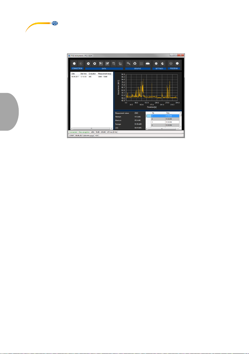
The main window consists of several areas:
Below the title bar there is a "toolbar", the icons of which are functionally grouped.
Below this toolbar, there is a list of measurement series, in the left part of the window.
The right part of the window is divided into an upper and a lower part.
The upper part is the area for graphical representation of the measured values.
The lower part, on the other hand, provides an overview of statistical data and also a tabular
listing of the measured values.
At the bottom of the main window there are two “status bars” containing important information,
directly above each other.
The lower of the two shows the static settings of the program which can be set via a settings
dialog (COM port, date and time format).
The upper status bar shows the dynamic settings of the "PCE-322A" which are retrieved directly
from the connected device.
© PCE Instruments
11
Page 15
English
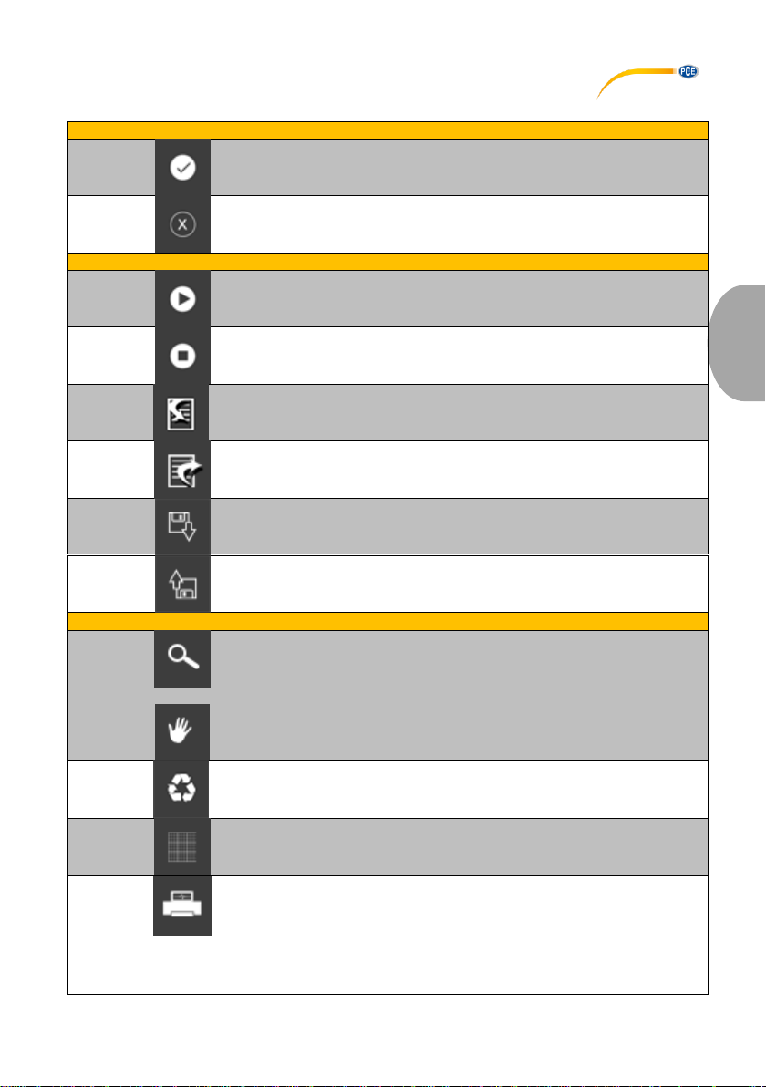
5 Meaning of the Individual Icons on the Toolbar
Group "Connection"
Connect to the "PCE-322A"
Disconnect from the "PCE-322A"
Group "Data"
Start a measurement
Stop a measurement
Import a series of measurements from the "PCE-322A"
Export a series of measurements
Load a series of measurements from a file
Save a series of measurements in a file
Group "Graphics"
Enlarge the graphics area ("Zooming") or move the enlarged
graphics
Restore the orginal graphics
Change the background and representation of the graphics
Print the currently visible graphics
© PCE Instruments
12
Page 16
English
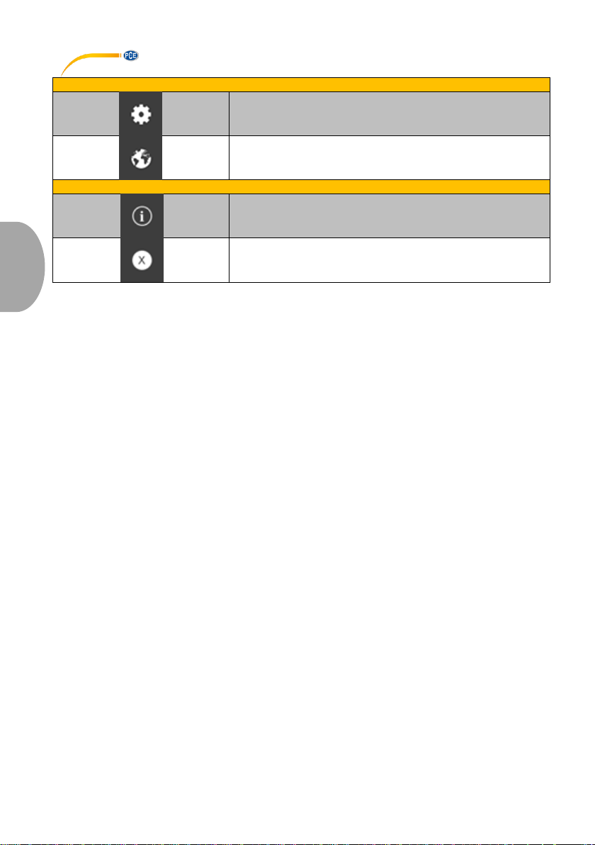
Group "Settings"
Open settings dialogue
Select one of the languages supported by the programme
Group "Program"
Display an information dialog
Exit the program
© PCE Instruments
13
Page 17
English
6 Operation
6.1 The first use of the software
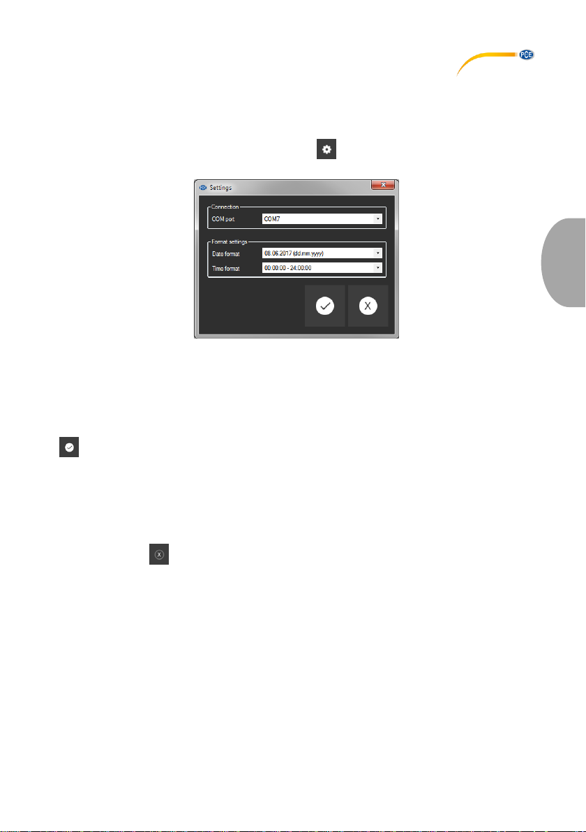
Before the "PCE-322A" can work with the software, the assigned COM port must be set in the
software once. It can be set via the “settings dialog”
In addition to the connection data, further settings for the date and time format can be made
here.
6.2 Connect to the "PCE-322A"
After the desired settings have been made and the settings dialog has been closed with a click
on the "Apply" button, the connection to the "PCE-322A" can be established by clicking on the
icon.
If the connection could be successfully established, the term "Connected" is displayed in green
on the status bar for the dynamic data.
If, however, no connection is established, the term "Disconnected" is displayed in red.
6.3 Disconnect from the “PCE-322A”
By clicking on the icon, an active connection to the "PCE-322A" can be terminated.
If you exit the software while the connection is active, the connection will also be terminated.
© PCE Instruments
14
Page 18
English
6.4 List of measurement series
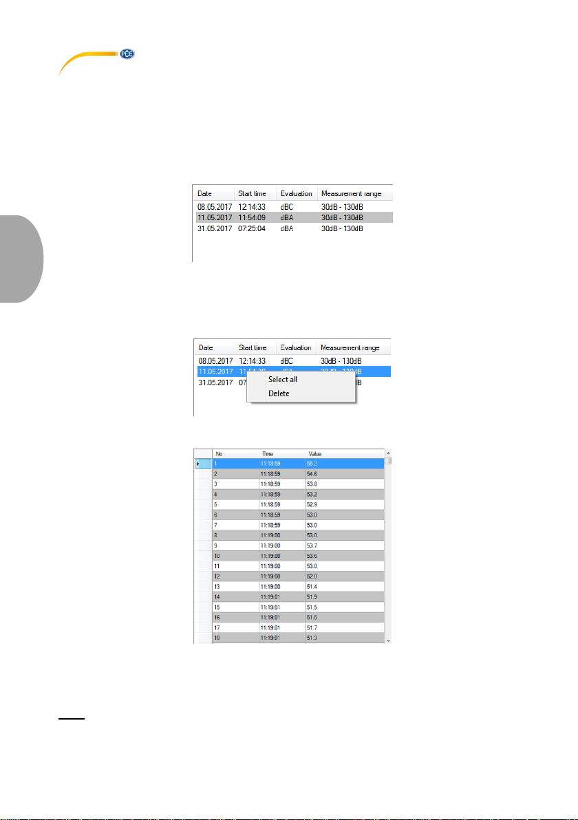
In the left part of the main window all the series of measurements are listed, which are currently
in the memory of the PC. Each series of measurements is represented in the list with the date of
creation, the start time of the measurement, the selected weighting (dBA / dBC) and the
measurement range.
Depending on what series of measurements has been selected, the graphics, the chart and also
the statistical data are updated.
A right click allows you to select all series of measurements or to delete one or several
highlighted series of measurements.
6.5 Numerical display
In the lower part of the main window, all the measured values are tabulated.
The chart can be sorted by columns by clicking on the respective column heading
("No.", "Time" or "Value").
Note:
These data come directly from the "PCE-322A"; the time can thus deviate from the PC time.
© PCE Instruments
15
Page 19
English
6.6 Statistical data
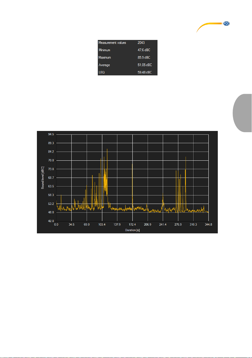
The statistics include the number of measured points, the smallest and largest measured sound
levels, the average value and the calculated LEQ value ("equivalent continuous sound level",
energy equivalent averaging according to DIN 45 641).
6.7 Graphical representation
In the area for the graphical evaluation, the selected weighting (dBA / dBC) is shown on the y
axis and the temporal trend (in seconds) is shown on the x axis.
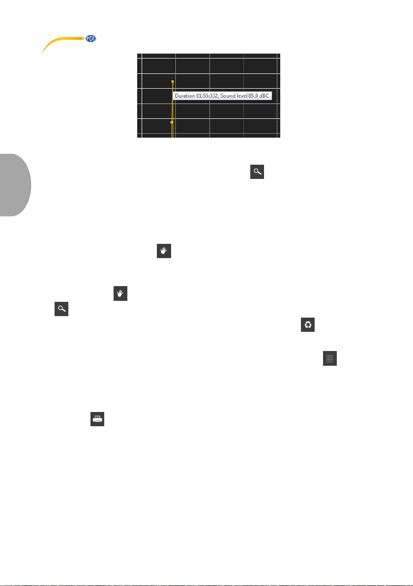
Moving the mouse cursor to a point in the displayed line makes a small information window with
the data (time and unit) of the currently selected measurement value pop up after a short time.
© PCE Instruments
16
Page 20
English
A freely selectable part of the displayed graphics can be enlarged.
For this purpose, the corresponding icon in the toolbar (“Enlarge the graphics area ("Zooming")
or move the enlarged graphics) must be a magnifying glass .
Then, a rectangle can be drawn over a part of the graphics by holding the mouse button down.
When the mouse is released, the selected area appears as a new graphic.
As soon as at least one enlargement has been made, it is possible to switch from enlargement
mode to shift mode by clicking the icon (“Enlarge the graphics area ("Zooming") or move the
enlarged graphics) with the magnifying glass icon.
Shift mode is represented by the icon.
If the mouse is now placed over the graphics area and then the left mouse button is pressed,
the depicted section can be moved by holding the mouse button down.
Another click on the icon changes back to the enlargement mode, which is recognizable by
the icon.
The original graphics can be restored at any time by clicking on the icon next to the
magnifying glass or hand.
The background of the graphics and its representation can be changed via the icon to the
right. A click on the icon works like a switch:
A single click makes the division of the background finer and adds some more dots to the
graphics. A further click on the icon changes back to standard view.
The currently displayed graphics can also be printed.
A click on the icon opens the "Print" dialog.
© PCE Instruments
17
Page 21
English
6.8 Performing the measurement
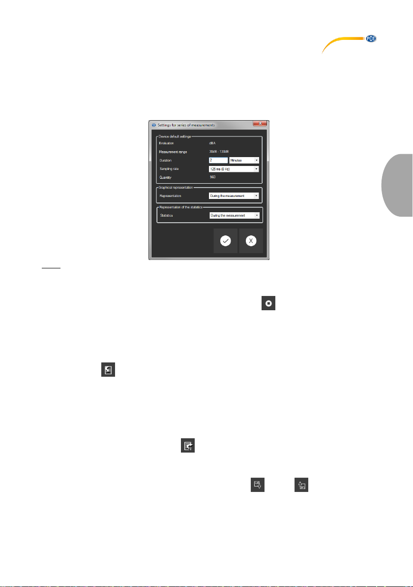
If an active connection to the "PCE-322A" is present, a new measurement can be started.
After clicking on the corresponding icon in the toolbar ("Start a measurement"), a new dialog
(Fig. 14) is then displayed, with the help of which additional options, relevant for the upcoming
measurement, can be determined.
Note:
Neither the evaluation nor the measurement range can be set via the software.
They are taken directly from the "PCE-322A" settings.
An ongoing measurement can be terminated by clicking on the icon in the toolbar.
6.9 Data import
The internal device memory can then be read out using the software and thus the recorded
series of measurements can be made available via an import.
Just click on the icon in the toolbar. You will then be asked if you really want to import the
series of measurements from the device. This can take a few minutes, depending on the extent.
The data import can now be started by clicking on the "OK" button or cancelled by clicking on
the “Cancel” button.
6.10 Export of series of measurements
Measurement series can also be exported. The entire content of one measurement series can
be exported in CSV format by using the icon of the toolbar.
6.11 Loading and saving series of measurements
A series of measurements can be loaded and saved via the and the icon in the toolbar.
© PCE Instruments
18
Page 22

English
PCE Instruments contact information
Germany France Spain
PCE Deutschland GmbH PCE Instruments France EURL PCE Ibérica S.L.
Im Langel 4 23, rue de Strasbourg Calle Mayor, 53
D-59872 Meschede 67250 SOULTZ-SOUS-FORETS 02500 Tobarra (Albacete)
Deutschland France España
Tel.: +49 (0) 2903 976 99 0 Téléphone: +33 (0) 972 3537 17 Tel. : +34 967 543 548
Fax: +49 (0) 2903 976 99 29 Numéro de fax: +33 (0) 972 3537 18 Fax: +34 967 543 542
[email protected] [email protected] [email protected]
www.pce-instruments.com/deutsch www.pce-instruments.com/french www.pce-instruments.com/espanol
United States of America United Kingdom Italy
PCE Americas Inc. PCE Instruments UK Ltd PCE Italia s.r.l.
711 Commerce Way suite 8 Units 12/13 Southpoint Business Park Via Pesciatina 878 / B-Interno 6
Jupiter / Palm Beach Ensign Way, Southampton 55010 LOC. GRAGNANO
33458 FL Hampshire CAPANNORI (LUCCA)
USA United Kingdom, SO31 4RF Italia
Tel: +1 (561) 320-9162 Tel: +44 (0) 2380 98703 0 Telefono: +39 0583 975 114
Fax: +1 (561) 320-9176 Fax: +44 (0) 2380 98703 9 Fax: +39 0583 974 824
[email protected] [email protected] [email protected]
www.pce-instruments.com/us www.pce-instruments.com/english www.pce-instruments.com/italiano
The Netherlands Chile Hong Kong
PCE Brookhuis B.V. PCE Instruments Chile S.A. PCE Instruments HK Ltd.
Institutenweg 15 RUT: 76.154.057-2 Unit J, 21/F., COS Centre
7521 PH Enschede Santos Dumont 738, local 4 56 Tsun Yip Street
Nederland Comuna de Recoleta, Santiago, Chile Kwun Tong
Telefoon: +31 (0) 900 1200 003 Tel. : +56 2 24053238 Kowloon, Hong Kong
Fax: +31 53 430 36 46 Fax: +56 2 2873 3777 Tel: +852-301-84912
[email protected] [email protected] [email protected]
www.pce-instruments.com/dutch www.pce-instruments.com/chile www.pce-instruments.cn
China
PCE (Beijing) Technology Co.,Ltd PCE Teknik Cihazları Ltd.Şti.
1519 Room, 6 Building Halkalı Merkez Mah.
Men Tou Gou Xin Cheng, Pehlivan Sok. No.6/C
Men Tou Gou District 34303 Küçükçekmece - İstanbul
102300 Beijing Türkiye
China Tel: 0212 471 11 47
Tel: +86 (10) 8893 9660 Faks: 0212 705 53 93
[email protected] [email protected]
www.pce-instruments.cn www.pce-instruments.com/turkish
Turkey
© PCE Instruments
19
Page 23

© PCE Instruments
Page 24

Specifications are subject to change without notice.
User manuals in various languages (français, italiano, español,
português, nederlands, türk, polski, русский, 中文) can be found by
using our product search on: www.pce-instruments.com
© PCE Instruments
 Loading...