

User Manual
User manuals in various languages (français,
italiano, español, português, nederlands, türk, polski,
русский, 中文) can be found by using our
product search on: www.pce-instruments.com
Last change: 3 May 2019
v1.0
English
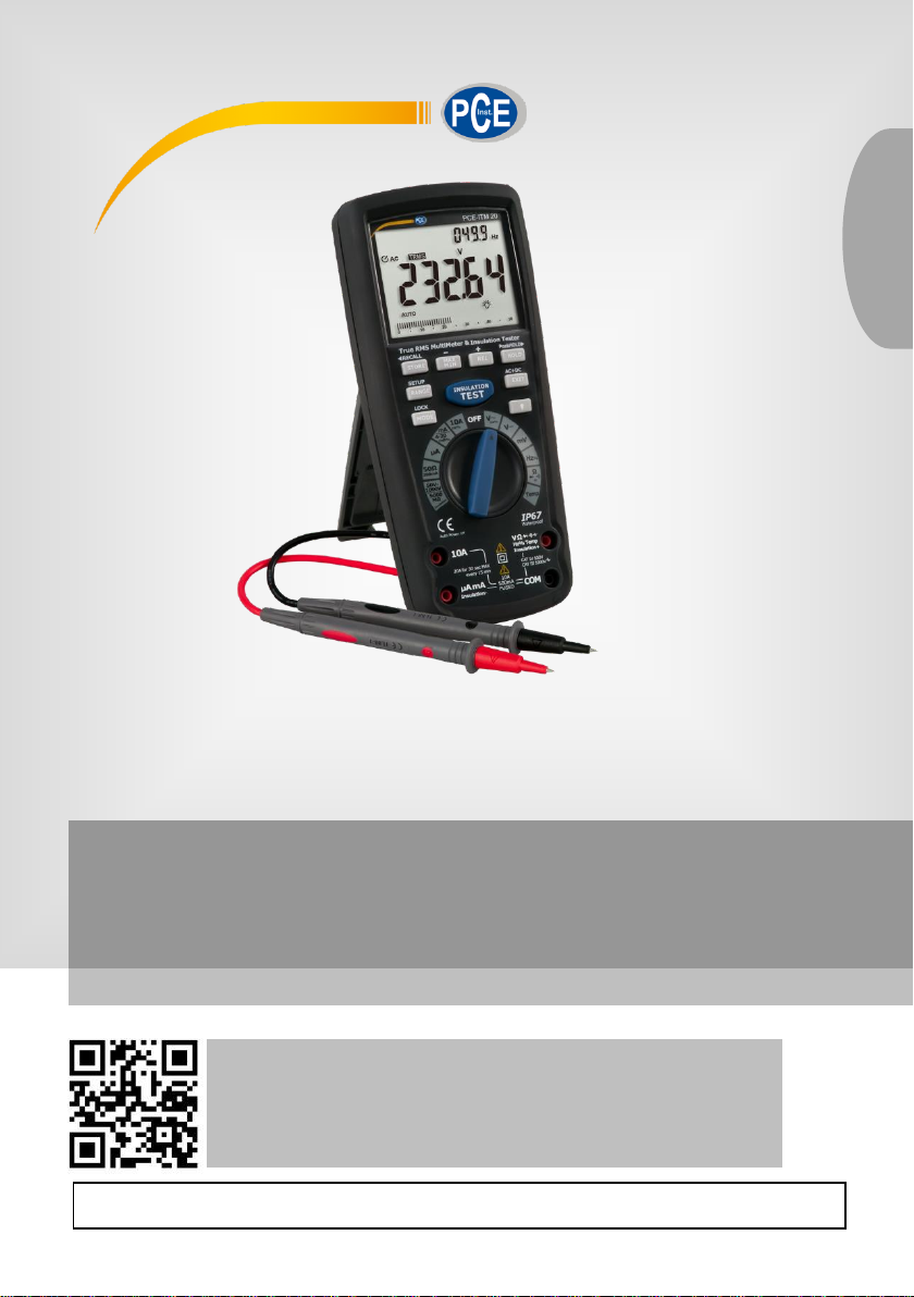
Isolation Meter PCE-ITM 20
PCE-ITM 20
© PCE Instruments

© PCE Instruments
Contents
1 Safety notes ........................................................................................... 1
1.1 Safety symbols ................................................................................................................. 2
1.2 IEC1010 overvoltage installation categories ..................................................................... 2
2 Device description ................................................................................ 3
3 Operation ............................................................................................... 5
3.1 DC Voltage Measurements .............................................................................................. 5
3.2 AC Voltage (Frequency, Duty Cycle) Measurements ........................................................ 6
3.3 mV Voltage Measurements .............................................................................................. 7
3.4 DC Current Measurements ............................................................................................... 8
3.5 AC Current (Frequency, Duty Cycle) Measurements ........................................................ 9
3.6 Resistance Measurements ..............................................................................................10
3.7 Continuity Check .............................................................................................................11
3.8 Diode Test .......................................................................................................................12
3.9 Capacitance Measurements ............................................................................................12
3.10 Temperature Measurements ...........................................................................................13
3.11 Frequency (Duty Cycle) Measurements (electronic) ........................................................13
3.12 % 4 – 20mA Measurements ............................................................................................14
3.13 LO Measurements ...........................................................................................................14
3.14 Insulation Resistance Measurements ..............................................................................14
3.15 Application Example ........................................................................................................15
3.16 Autoranging/Manual Range Selection .............................................................................16
3.17 MAX/MIN.........................................................................................................................16
3.18 Relative Mode .................................................................................................................17
3.19 Display Backlight .............................................................................................................17
3.20 HOLD ..............................................................................................................................17
3.21 PEAK HOLD ...................................................................................................................17
3.22 Data Record (Store/Recall) .............................................................................................17
3.23 Parameter setting up (SET) .............................................................................................18
3.24 AC+DC............................................................................................................................18
3.25 Low Battery Indication .....................................................................................................18
3.26 Calibration Method ..........................................................................................................18

© PCE Instruments
4 Maintenance ........................................................................................ 19
4.1 Battery Installation ...........................................................................................................19
4.2 Replacing the Fuses........................................................................................................20
5 Technical specifications .................................................................... 20
6 Test method of DAR and PI ................................................................ 24
7 Warranty ............................................................................................... 25
8 Disposal ............................................................................................... 25


© PCE Instruments
1
1 Safety notes
Please read this manual carefully and completely before you use the device for the first time. The
device may only be used by qualified personnel and repaired by PCE Instruments personnel.
Damage or injuries caused by non-observance of the manual are excluded from our liability and
not covered by our warranty.
• The device must only be used as described in this instruction manual. If used otherwise,
this can cause dangerous situations for the user and damage to the meter.
• The instrument may only be used if the environmental conditions (temperature, relative
humidity, …) are within the ranges stated in the technical specifications. Do not expose
the device to extreme temperatures, direct sunlight, extreme humidity or moisture.
• Do not expose the device to shocks or strong vibrations.
• The case should only be opened by qualified PCE Instruments personnel.
• Never use the instrument when your hands are wet.
• You must not make any technical changes to the device.
• The appliance should only be cleaned with a damp cloth. Use only pH-neutral cleaner,
no abrasives or solvents.
• The device must only be used with accessories from PCE Instruments or equivalent.
• Before each use, inspect the case for visible damage. If any damage is visible, do not
use the device.
• Do not use the instrument in explosive atmospheres.
• The measurement range as stated in the specifications must not be exceeded under
any circumstances.
• NEVER apply voltage or current to the meter that exceeds the specified maximum:
Input Protection Limits
Function
Maximum input
V DC or V AC
1000 VDC/AC RMS
mA AC/DC
500 mA 1000 V fast acting fuse
A AC/DC
10 A 1000 V fast acting fuse (20 A for 30
seconds max. every 15 min)
Frequency, resistance, capacitance,
duty cycle, diode test, continuity
1000 VDC/AC rms
Temperature
1000 VDC/AC RMS
Surge protection
8 kV peak in line with IEC 61010
• USE EXTREME CAUTION when working with high voltages.
• DO NOT measure voltage if the voltage on the “COM” input jack exceeds 1000 V above
earth ground.
• NEVER connect the meter leads across a voltage source while the function switch is in
the current, resistance, or diode mode. Doing so can damage the meter.
• ALWAYS discharge filter capacitors in power supplies and disconnect the power when
making resistance or diode tests.
• ALWAYS turn off the power and disconnect the test leads before opening the covers to
replace the fuse or batteries.
• NEVER operate the meter unless the back cover and the battery and fuse covers are
in place and fastened securely.
• If the equipment is used in a manner not specified by the manufacturer, the protection
provided by the equipment may be impaired.
• Do not use the meter or test leads if they look damaged. Use extreme caution when
working around bare conductors or bus bars.
• Accidental contact with the conductor could result in electric shock.
• Be careful when working with voltages above 60 V DC or 30 V AC RMS. Such voltages
pose a shock hazard.

© PCE Instruments
2
• Before making resistance measurements or testing acoustic continuity, disconnect the
circuit from the main power supply and all loads from the circuit.
• Non-observance of the safety notes can cause damage to the device and injuries to
the user.
We do not assume liability for printing errors or any other mistakes in this manual.
We expressly point to our general guarantee terms which can be found in our general terms of
business.
If you have any questions please contact PCE Instruments. The contact details can be found at
the end of this manual.
1.1 Safety symbols
This symbol can appear next to another symbol, device or connection and
indicates the user must refer to the manual for important safety information.
This WARNING symbol indicates a potentially hazardous situation which, if
not avoided, could result in death or serious injury.
This CAUTION symbol indicates a potentially hazardous situation which, if
not avoided, may result in damage to the product.
Indicates the terminal(s) so marked must not be connected to a circuit where
the voltage with respect to earth ground exceeds 1000 VAC or VDC.
This symbol adjacent to one or more terminals identifies them as being
associated with ranges that may, in normal use, be subject to particularly
hazardous voltages. For maximum safety, the meter and its test leads should
not be handled when these terminals are energized.
Equipment is protected by double or reinforced insulation.
1.2 IEC1010 overvoltage installation categories
OVERVOLTAGE CATEGORY I
Equipment of OVERVOLTAGE CATEGORY I is equipment for connection to circuits in which
measures are taken to limit the transient overvoltages to an appropriate low level.
Note-Examples include protected electronic circuits.
OVERVOLTAGE CATEGORY II
Equipment of OVERVOLTAGE CATEGORY II is energy-consuming equipment to be supplied
from the fixed installation.
Note-Examples include household, office, and laboratory appliances.
OVERVOLTAGE CATEGORY III
Equipment of OVERVOLTAGE CATEGORY III is equipment in fixed installations.
Note-Examples include switches in the fixed installations and some equipment for industrial use
with permanent connection to the fixed installation.
OVERVOLTAGE CATEGORY IV
Equipment of OVERVOLTAGE CATEGORY IV is for use at the origin of the installation.
Note-Examples include electricity meters and primary over-current protection equipment.

© PCE Instruments
3
2 Device description
Device / keys
1 - 50,000 count LCD
2 - MAX/MIN (-) button
3 - STORE (<RECALL) button
4 - RANGE (SETUP) button
5 - MODE (LOCK) button
6 - INSULATION TEST button
7 - Function switch
8 - 10 A input jacks
9 - mA, μA and insulation input jacks
10 - COM input jack
11 - Positive input jack
12 - Backlight button
13 – EXIT (AC+DC) button
14 – HOLD (PeakHOLD>) button
15 – REL (+) button
The tilt stand and battery compartment are
on the rear side of the unit.

© PCE Instruments
4
Display
n
μ
m
A
k
F
M
Ω
PEAK
Hz
V
%
∆
AC
AUTO
DC
HOLD
˚F
˚C
MAX
MIN
No.
S
SET
AC + DC
TRMS
STO
RCL
Continuity
Diode test
Battery status
nano (10-9) (capacitance)
micro (10-6) (amps, cap)
milli (10-3) (volts, amps)
Amps
kilo (103) (ohms)
Farads (capacitance)
mega (106) (ohms)
Ohms
Peak Hold
Hertz (frequency)
Volts
Per cent (duty ratio)
Relative
Alternating current
Autoranging
Direct current
Display hold
Degrees Fahrenheit
Degrees Centigrade
Maximum
Minimum
Serial number
Second
Setup parameter
Alternating current
+ direct current
True RMS
Store
Recall
Auto Power Off enabled
Backlight
RF transmitter active

© PCE Instruments
5
Other symbols
: While testing the insulation resistance, the symbol “ ” flashes frequently if the voltage is over
30 V.
: While testing the insulation resistance, the symbol “ ” flashes frequently and the buzzer
warns continually if the outside voltage is over 30 V. The symbol “ ” is indicated while LOΩ≤35Ω
and the buzzer warns continuously.
LOCK: Push down the “LOCK” button while you are testing the insulation resistance. The meter
will enter insulation resistance status and the symbol “ ” is indicated.
LOBAT: The display shows “LOBAT” when the voltage drops below 7.5 V.
HOLD: The current value is held.
V, MΩ, Ω: The measured dimension units
3 Operation
Risk of electrocution. High-voltage circuits, both AC and DC, are very
dangerous and should be measured with great care.
• ALWAYS turn the function switch to the OFF position when the meter is not in use.
• If “OL” appears in the display during a measurement, the value exceeds the range you have
selected. Change to a higher range.
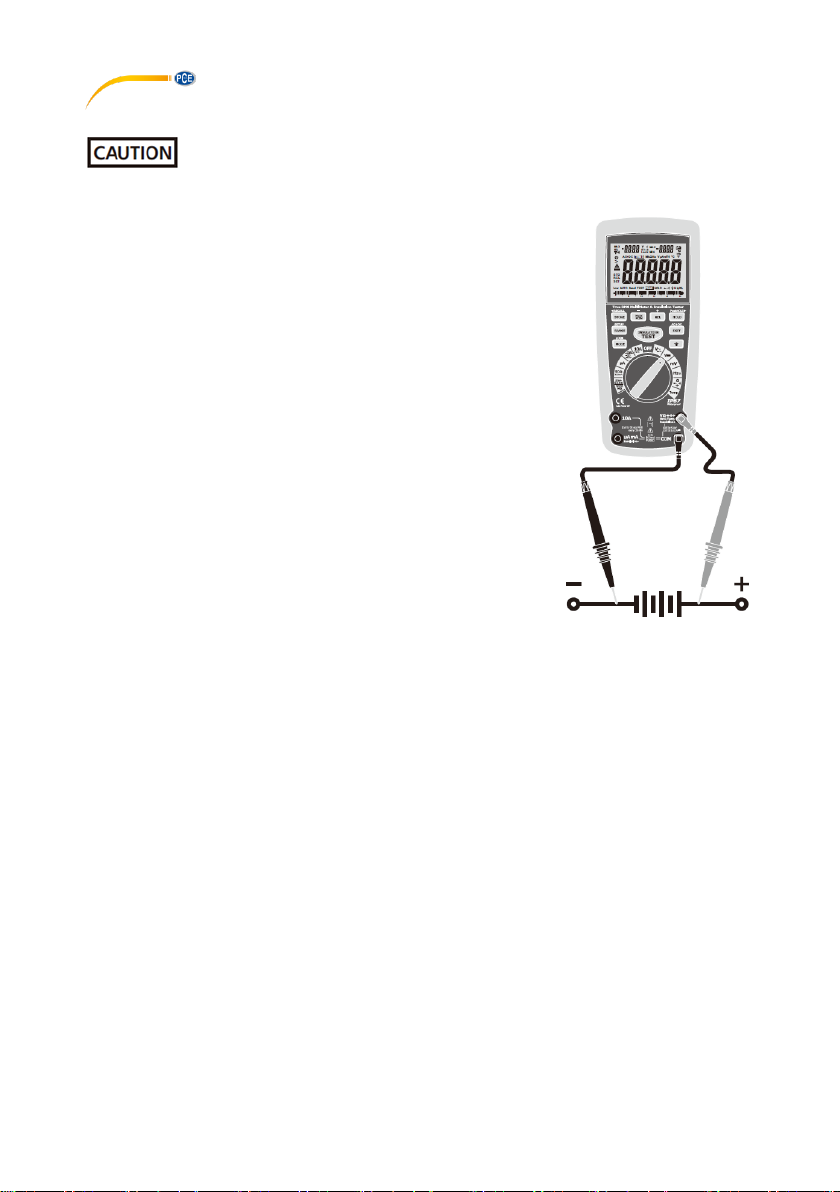
3.1 DC Voltage Measurements
Do not measure DC voltages if a motor on the circuit is being switched ON or
OFF. Large voltage surges may occur that can damage the meter.
• Set the function switch to the green VDC position.
• Insert the black test lead banana plug into the negative COM
jack. Insert the red test lead banana plug into the positive V
jack.
• Touch the black test probe tip to the negative side of the
circuit. Touch the red test probe tip to the positive side of the
circuit.
• Read the voltage in the display.

© PCE Instruments
6
3.2 AC Voltage (Frequency, Duty Cycle) Measurements
Risk of Electrocution. The probe tips may not be long enough to contact
the live parts inside some 240 V outlets for appliances because the contacts are
recessed deep in the outlets. As a result, the reading may show 0 volts when the outlet
actually has voltage on it. Make sure the probe tips are touching the metal contacts
inside the outlet before assuming that no voltage is present.
Do not measure AC voltages if a motor on the circuit is being switched ON
or OFF. Large voltage surges may occur that can damage the meter.
• Set the function switch to the green VAC/Hz/% position.
• Insert the black test lead banana plug into the negative
COM jack. Insert red test lead banana plug into the positive
V jack.
• Touch the black test probe tip to the neutral side of the
circuit. Touch the red test probe tip to the “hot” side of the
circuit.
• Read the voltage in the main display and the frequency in
the right auxiliary display.
• Press the MODE button to indicate “Hz”.
• Read the frequency in the main display.
• Press the MODE button again to indicate “%”.
• Read the % of duty cycle in the main display.
• Press EXIT for 2 seconds into the function of AC+DC. Test
DC and AC TRUE RMS.
• When the voltage of VAC>0.2V, the frequency of VAC can
be read synchronously in the right auxiliary display.
© PCE Instruments
7
3.3 mV Voltage Measurements
Do not measure mV voltages if a motor on the circuit is being switched ON or
OFF. Large voltage surges may occur that can damage the meter.
• Set the function switch to the green mV position.
• Press the MODE button to indicate “DC ”or “AC ”, or in AC
range press EXIT for two seconds and choose ”AC+DC”.
• Insert the black test lead banana plug into the negative COM
jack. Insert the red test lead banana plug into the positive V
jack.
• Touch the black test probe tip to the negative side of the
circuit. Touch the red test probe tip to the positive side of the
circuit.
• Read the mV voltage in the main display.
• When mVac>2mV, the frequency of mVac can be read
synchronously in the right auxiliary display.

© PCE Instruments
8
3.4 DC Current Measurements
Do not make 20A current measurements for longer than 30 seconds.
Exceeding 30 seconds may cause damage to the meter and/or the test leads.
• Insert the black test lead banana plug into the negative
COM
jack.
• For current measurements up to 5000 μA DC, set the
function
switch to the yellow μA position and insert the red test lead
banana plug into the μA/mA jack.
• For current measurements up to 500 mA DC, set the
function
switch to the yellow mA position and insert the red test lead
banana plug into the μA/mA jack.
• For current measurements up to 20 A DC, set the function
switch to the yellow 10A/HZ/% position and insert the red
test
lead banana plug into the 10 A jack.
• Press the MODE button to indicate “DC” on the display.
• Remove power from the circuit under test, then open up the
circuit at the point where you wish to measure current.
• Touch the black test probe tip to the negative side of the
circuit. Touch the red test probe tip to the positive side of the
circuit.
• Apply power to the circuit.
• Read the current in the display.

© PCE Instruments
9
3.5 AC Current (Frequency, Duty Cycle) Measurements
Do not make 20A current measurements for longer than 30 seconds.
Exceeding 30 seconds may cause damage to the meter and/or the test leads.
• Insert the black test lead banana plug into the negative COM
jack.
• For current measurements up to 5000μA AC, set the function
switch to the yellow μA position and insert the red test lead
banana plug into the μA/mA jack.
• For current measurements up to 500mA AC, set the function
switch to the yellow mA position and insert the red test lead
banana plug into the μA/mA jack.
• For current measurements up to 20A AC, set the function
switch to the yellow 10A/HZ/% position and insert the red test
lead banana plug into the 10A jack.
• Press the MODE button to indicate “AC” on the display.
• Remove power from the circuit under test, then open up the
circuit at the point where you wish to measure current.
• Touch the black test probe tip to the neutral side of the circuit.
Touch the red test probe tip to the “hot” side of the circuit.
• Apply power to the circuit.
• Read the current in the display. In the 10A AC range, the right
auxiliary displays frequency.
• Press and hold the MODE button to indicate “Hz”.
• Read the frequency in the display.
• Momentarily press the MODE button again to indicate “%”.
• Read the % duty cycle in the display.
• Press and hold the MODE button to return to current
measurement.
• Press EXIT for 2 seconds into the function of AC+DC. Test
DC and AC TRUE Rms.
• When uAac>2mA, mAac>2mA, 10Aac >0.2A, the current
frequency can be read synchronously in the right auxiliary
display.

© PCE Instruments
10
3.6 Resistance Measurements
To avoid electric shock, disconnect power to the unit under test and
discharge all capacitors before taking any resistance measurements. Remove the batteries
and unplug the line cords.
• Set the function switch to the green Ω CAP
position.
• Insert the black test lead banana plug into
the negative COM jack. Insert the red test
lead banana plug into the positive Ω jack.
• Press the MODE button to indicate “Ω” on
the display.
• Touch the test probe tips across the circuit
or part under test. It is best to disconnect
one side of the part under test so the rest
of the circuit will not interfere with the
resistance reading.
• Read the resistance in the display.

© PCE Instruments
11
3.7 Continuity Check
To avoid electric shock, never measure continuity on circuits or wires that
have voltage on them.
• Set the function switch to the green Ω CAP
position.
• Insert the black lead banana plug into the negative
COM jack. Insert the red test lead banana plug into the
positive Ω jack.
• Press the MODE button to indicate “ ” and “Ω” on the
display.
• Touch the test probe tips to the circuit or wire you wish
to check.
• If the resistance is less than approximately 35Ω, the
audible signal will sound. If the circuit is open, the
display will indicate “OL”.

© PCE Instruments
12
3.8 Diode Test
• Set the function switch to the green Ω CAP
position.
• Insert the black test lead banana plug into the negative
COM jack and the red test lead banana plug into the
positive V jack.
• Press the MODE button to indicate “ ” and “V” on the
display.
• Touch the test probes to the diode under test. Forward
voltage will typically indicate 0.400 … 0.700V. Reverse
voltage will indicate “OL”. Shorted devices will indicate
near 0V and an open device will indicate “OL” in both
polarities.
3.9 Capacitance Measurements
To avoid electric shock, disconnect power to the unit under test and
discharge all capacitors before taking any capacitance measurements. Remove the
batteries and unplug the line cords.
• Set the rotary function switch to the green Ω CAP
position.
• Insert the black test lead banana plug into the negative
COM jack.
• Insert the red test lead banana plug into the positive V
jack.
• Press the MODE button to indicate “F”
• Touch the test leads to the capacitor to be tested.
• Read the capacitance value in the display

© PCE Instruments
13
3.10 Temperature Measurements
• Set the function switch to the green Temp position.
• Insert the Temperature Probe into the input jacks, making
sure to observe the correct polarity.
• Press the MODE button to indicate “ºF” or “ºC”.
• Touch the Temperature Probe head to the part whose
temperature you wish to measure. Keeps the probe touching
the part under test until the reading stabilizes (about 30
seconds).
• Read the temperature in the display.
Note:
The temperature probe is fitted with a K-type mini connector. A
mini connector to banana connector adaptor is supplied for
connection to the input banana jacks.
3.11 Frequency (Duty Cycle) Measurements (electronic)
• Set the rotary function switch to the green H z/%
position.
• Insert the black lead banana plug into the negative COM
jack and the red test lead banana p lug into the positive
Hz jack.
• Touch the test probe tips to the circuit under test.
• Read the frequency on the display.
• Press the MODE button to indicate “%”.
• Read the % duty cycle in the display.

© PCE Instruments
14
3.12 % 4 – 20mA Measurements
• Set up and connect as described for DC mA measurements.
• Set the rotary function switch to the 4-20mA% position. Press and hold the MODE button to
indicate “%4-20mA”.
• The meter will display loop current as a % with 0mA=-25%, 4mA=0%, 20mA=100%, and
24mA=125%.
3.13 LO Measurements
• Set the function switch to the green 50Ω/200mA position.
• Insert the black test lead banana plug into the negative INSULATION- jack. Insert the red test
lead banana plug into the positive jack.
• Connect the tips of the test leads to both ends of the circuit under test. read resistance in Ω on
the LCD. The two ranges (50.000/500.00Ω) can be switched automatically; the primary display
of the resistance in Ω, flashes synchronously with the analog bar.
• When the impedance on circuit is below approximately ≤35Ω.It will indicate by a continuous
beeper.
• The current is from 200 to 220mA while the tested resistance is 0Ω.
3.14 Insulation Resistance Measurements
• Set the function switch to the green 50~1000V/5000MΩ position.
• Press the RANGE key to step through the available voltages until you select the voltage you
want. You can choose 50V, 125V, 250V, 500V or 1000V. There are 4 ranges: 4MΩ, 40MΩ,
400MΩ, 4000MΩ, can be switched automatically for every voltage block.
• Primary display shows insulation resistance and unit is MΩ, synchronized with analog bar. The
left auxiliary display shows current insulation voltage outpour measurement, the right auxiliary
display shows setting insulation voltage outpour measurement, unit V.
• Before measurement check the voltage range of tested device is applicable to the requirement
of insulation measurement voltage. Please ensure there are no parts that will be damaged by
insulation measurement voltage. Many parts will be damaged undue 1000V (and other ranges).
For example, power factor capacitor, low voltage insulation cable, electronic dimmer and
common electronic parts are all possible to be damaged under 1000V (and other ranges). Turn
to related voltage range after confirming the voltage.
• Connect two measurement leads to tested device; Push down and hold the “TEST” button /or
press the “LOCK” key first and then the “TEST” button, if the tested is electriferous and its
voltage (AC/DC) is over 30V, it will refuse work and no high-voltage testing occurs, simultaneity,
it shows “>30V” on the LCD, the symbol “ ” flashes, and the buzzer warns frequently. If the
tested is diselectriferous or its voltage is lower than 30V, it will enter into the formal testing
process and brings the high-voltage. On the primary display, the insulation resistance in MΩ is
indicated in-phase with analog bar; on the secondary display, the tested insulation voltage in V
(DC) is indicated, the symbol “ ” flashes and the buzzer warns frequently.
• Being free from the “TEST” button or pushing down the “TEST” button in the “LOCK” status can
exit from the “LOCK” status and shutoff the high-voltage, synchronously, the resistance values
is indicated in the primary display will be held, and the secondary display still be in the status of
monitoring the insulation voltage for the tested. Measurement is over. Subsequently, both ends
of the wire insulation voltage measurement by instrument internal electronic switch release
voltage.
• Turning the function switch can exit automatically from testing status during the process.
• Absorptance & Polarize measurement mode: In the insulation test condition, press the MAX/MIN
key to activate the Absorptance & Polarize measurement mode. The left auxiliary display shows
Absorptance measurement, the right auxiliary display shows Polarize measurement.

© PCE Instruments
15
3.15 Application Example
Power tools and small appliances
This test would also apply to other similar equipment that has a line cord. For double insulated
power tools, the megohmmeter lead shown connected to the housing would be connected to
some metal part of the tool (e. g. chuck, blade).
Note: The switch of the device must be in the “ON” position and the main power should be
disconnected.
Motors
AC-Disconnect the motor from the line by disconnecting the wires at the motor terminals or by
opening the main switch. If the main switch is used and the motor also has a starter then the
starter must be held, by some means, in the “ON” position. In the latter case, the measured
resistance will include the resistance of the motor, wire and all other components between the
motor and the main switch. If a weakness is indicated, the motor and other components should
be checked individually. If the motor is disconnected at the motor terminals, connect one
megohmmeter lead to the grounded motor housing and the other lead to one of the motor leads.
DC-Disconnect the motor from the line. To test the brush rigging, field coils and armature, connect
one megohmmeter lead to the grounded motor housing and the other lead to the brush on the
commutator. If the resistance measurement indicates a weakness, raise the brushes off the
commutator and separately test the armature, field coils and brush rigging by connecting one
megohmmeter lead to each of them individually, leaving the other connected to the grounded
motor housing. The above also applies to DC generators.
Motor
Connect
to housing
(GND)
Starter
(must
be
“ON“)
Main
switch
Line
Connect
to motor
side of
switch

© PCE Instruments
16
Cables
Disconnect the cable from the line. Also disconnect opposite end to avoid errors due to leakage
from other equipment. Check each conductor to ground and /or lead sheath by connecting one
megohmmeter lead to a ground and /or lead sheather and the other megohmmeter lead to each
of the conductors in turn. Check insulation resistance between conductors by connecting
megohmmeter leads to conductors in pairs.
3.16 Autoranging/Manual Range Selection
When the meter is first turned on, it automatically goes into Autoranging. This automatically
selects the best range for the measurements being made and is generally the best mode for most
measurements. For measurement situations requiring that a range be manually selected, perform
the following:
1. Press the RANGE key. The “AUTO” display indicator will turn off.
2. Press the RANGE key to step through the available ranges until you select the range you want.
3. To exit the Manual Ranging mode and return to Autoranging, press EXIT
Note: Manual ranging does not apply for the Temperature functions.
3.17 MAX/MIN
1. Press the MAX/MIN key to activate the MAX/MIN recording mode. The display icon "MAX" will
appear. The meter left auxiliary display will display and hold the maximum reading and will update
only when a new “max” occurs. The display icon "MIN" will appear. The right auxiliary display
meter will display and hold the minimum reading and will update only when a new “min” occurs.
2. To exit MAX/MIN mode, press EXIT.

© PCE Instruments
17
3.18 Relative Mode
The relative measurement feature allows you to make measurements relative to a stored
reference value. A reference voltage, current, etc. can be stored and measurements made in
comparison to that value. The displayed value is the difference between the reference value and
the measured value. Note: Relative mode does not operate in the 4-20mA function.
1. Perform the measurement as described in the operating instructions.
2. Press the REL button to store the reading in the display and the "REL" indicator will appear on
the display.
3. Left auxiliary display displays the margin of initial value and the current value. Right auxiliary
display displays the initial reading. Main display the reading after REL TEST.
4. Press the EXIT button to exit the relative mode.
3.19 Display Backlight
Press the key to turn the backlight on. The backlight will automatically turn off after SET time.
Press the EXIT button to exit the backlight on mode.
3.20 HOLD
The hold function freezes the reading in the display. Press the HOLD key momentarily to activate
or to exit the HOLD function.
3.21 PEAK HOLD
The Peak Hold function captures the peak AC or DC voltage or current. The meter can capture
negative or positive peaks as fast as 1 millisecond in duration. Momentarily press the PEAK
button, “PEAK” and “MAX” will display in left auxiliary display. MIN” will display in right auxiliary
display. The meter will update the display each time a lower negative peak occurs. Press the
EXIT button to exit the PEAK HOLD mode. Auto Power Off feature will be disabled automatically
in this mode.
3.22 Data Record (Store/Recall)
1. STORE function
In the current testing mode, press STORE button one time, enter into STORE function. On the
left upper corner of LCD shows NO XXXX., which states current storage serial number. Then,
press button PEAKHOLD to change into the initial serial number 0000. (Press again it will change
back). On the right upper corner of LCD shows XXXX, which states how many current storage is
used. Press STORE button again, enter into recording interval time set up function. On the left
upper shows 0000 S, which states recording interval time; using button + & - to select, the range
is 0~255 seconds. When the recording interval time is 0000 S, then press STORE button again
to change into manual recording. Press the STORE button again to record once. When the
recording interval time is 1~255 S, then press STORE button again to start recording automatically
from 0000. Recording times is showed on the left upper corner, data is showed on the right upper
corner (Due to digital limitation, there is only display preceding four numbers) To finish above
STORE function, press EXIT button shortly. If you expect to clear all memory data: While power
on, hold EXIT button, and switch from OFF to random and then release EXIT button, the LCD will
flash thrice and buzzer thrice too, which means all memory data is cleared.

© PCE Instruments
18
2. RECALL function
Press STORE button two seconds to enter into RECALL function. On the left upper corner shows
XXXX , which states current storage serial number. On the right upper corner shows XXXX, which
states how many current storage is used. Press button PEAKHOLD shortly once to scan data
from 0000 to XXXX continuously. Press again then scan again. Use button + & — button to select
serial number XXXX on the left upper corner and record data on the right upper corner. To finish
above RECALL function, press EXIT button.
3.23 Parameter setting up (SET)
1.Press the RANGE button for seconds to enter into SET function. Then press once shortly,
change the setting content.
Setting content includes (in sequence): A: upper limit buzzer alarm
B: lower limit buzzer alarm
C: auto power off time
D: turn off phonating
E: back lit time
Use ←, +, -, → buttons to select the parameter
2.Press SET button continuously to switch to setting content, till exiting set up to testing mode.
So the updated setting content is saved. If press EXIT button in this period, all setting cannot
be saved.
3.24 AC+DC
In all the measuring mode VAC, mV(AC), 10A(AC), mA(AC), uA(AC), press button EXIT for 2
seconds to enter into AC+DC testing. The precision is the same as AC measurement. LCD shows
AC+DC signal. Press button EXIT to exit.
3.25 Low Battery Indication
When the icon appears alone in the display, the battery should be replaced.
3.26 Calibration Method
There is one method to use MCU calibration: manual panel keyboard method. (Only for
manufacturing, measurement and calibration, operation method is described in another
document).

© PCE Instruments
19
4 Maintenance
To avoid electric shock, disconnect the test leads from any source of voltage
before removing the back cover or the battery or fuse covers.
To avoid electric shock, do not operate your meter until the battery and fuse
covers are in place and fastened securely.
This multimeter is designed to provide years of dependable service, if the following
care instructions are observed:
• KEEP THE METER DRY. If it gets wet, wipe it off.
• USE AND STORE THE METER IN NORMAL TEMPERATURES. Temperature extremes can
shorten the life of the electronic parts and distort or melt plastic parts.
• HANDLE THE METER GENTLY AND CAREFULLY. Dropping it can damage the electronic
parts or the case.
• KEEP THE METER CLEAN. Wipe the case occasionally with a damp cloth. DO NOT use
chemicals, cleaning solvents or detergents.
• USE ONLY FRESH BATTERIES OF THE RECOMMENDED SIZE AND TYPE. Remove old or
weak batteries so they do not leak and damage the unit.
• IF THE METER IS TO BE STORED FOR A LONG PERIOD OF TIME, the batteries should be
removed to prevent damage to the unit.
4.1 Battery Installation
To avoid electric shock, disconnect the test leads from any source of voltage
before removing the battery cover.
• Turn power off and disconnect the test leads from the meter.
• Open the rear battery cover by removing two screws (B) using a Phillips head screwdriver.
• Insert the battery into battery holder, observing the correct polarity.
• Put the battery cover back in place. Secure with the screws.
To avoid electric shock, do not operate the meter until the battery cover is in
place and fastened securely.
Note:
If your meter does not work properly, check the fuses and batteries to make sure that they are
still good and that they are properly inserted.

© PCE Instruments
20
4.2 Replacing the Fuses
To avoid electric shock, disconnect the test leads from any source of voltage
before removing the meter cover.
• Disconnect the test leads from the meter.
• Remove the protective rubber holster.
• Remove the battery cover (two “B” screws) and the battery.
• Remove the six “A” screws securing the rear cover.
• Gently remove the old fuse and install the new fuse into the holder.
• Always use a fuse of the proper size and value (0.5A/1000V fast blow for the 500mA range,
10A/1000V fast blow for the 20A range
• Replace and secure the rear cover, battery and battery cover.
To avoid electric shock, do not operate your meter until the fuse cover is in
place and fastened securely.
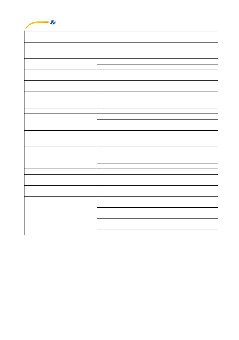
5 Technical specifications
Test voltage / test
current
Measuring
range
Resolution
Accuracy
50V 1-mA @ 50 kΩ
0.01 ... 5 MΩ
0.0001 MΩ
± (4 % + 20 digits)
5 ... 50 MΩ
0.001 MΩ
± (4 % + 20 digits)
50 ... 500 MΩ
0.01 MΩ
± (4 % + 20 digits)
500 ... 1000 MΩ
0.1 MΩ
not specified
125V / 1-mA @ 125 kΩ
0.01 ... 5 MΩ
0.001 MΩ
± (2 % + 20 digits)
5 .... 50 MΩ
0.001 MΩ
± (2 % + 20 digits)
50 ... 500 MΩ
0.01 MΩ
± (3 % + 20 digits)
500 .... 5000 MΩ
0.1 MΩ
± (4 % + 20 digits)
250V / 1-mA @ 250 kΩ
0.01 ... 5 MΩ
0.0001 MΩ
± (2 % + 20 digits)
5 ... 50 MΩ
0.001 MΩ
± (2 % + 20 digits)
50 ... 500 MΩ
0.01 MΩ
± (3 % + 20 digits)
500 ... 5000 MΩ
0.1 MΩ
± (4 % + 20 digits)
500V / 1-mA @ 500 kΩ
0.01 ... 5 MΩ
0.0001 MΩ
± (2 % + 20 digits)
5 ... 50 MΩ
0.001 MΩ
± (2 % + 20 digits)
50 ... 500 MΩ
0.01 MΩ
± (3 % + 20 digits)
500 ... 5000 MΩ
0.1 MΩ
± (4 % + 20 digits)
1000V / 1-mA @ 1000
kΩ
0.01 ... 5 MΩ
0.0001 MΩ
± (2 % + 20 digits)
5 ... 50 MΩ
0.001 MΩ
± (2 % + 20 digits)
50 ... 500 MΩ
0.01 MΩ
± (3 % + 20 digits)
500 ... 5000 MΩ
0.1 MΩ
± (4 % + 20 digits)
Short circuit current
<1.5-mA

© PCE Instruments
21
Multimeter
Measuring range
Resolution
Accuracy
Measuring parameters
50 mV
0.001 mV
± (0.06 %+ 20 digits)
DC
500 mV
0.01 mV
± (0.06 %+ 6 digits)
5 V
0.0001 V
± (0.06 %+ 4 digits)
50 V
0.001 V
± (0.06 %+ 4 digits)
500 V
0.01 V
± (0.06 %+ 4 digits)
1000 V
0.1 V
± (0.1 %+ 3 digits)
AC
50 mV
0.001 mV
± (1 % + 50 digits)
AC + DC
500 mV
0.01 mV
± (1 % + 50 digits)
50 .... 1000 Hz
5 V
0.0001 V
± (1 % + 30 digits)
50 V
0.001 V
± (1 % + 30 digits)
500 V
0.01 V
± (1 % + 30 digits)
1000 V
0.1 V
± (1 % + 30 digits)
The specified accuracy for alternating voltage refers to 5 ... 100% of the measuring
range
Direct current
Measuring range
Resolution
Accuracy
500 µA
0.01 µA
± (0.5 % + 3 digits)
5000 µA
0.1 µA
± (0.5 % + 3 digits)
50 mA
0.001 mA
± (0.5 % + 3 digits)
500 mA
0.01 A
± (0.5 % + 3 digits)
10 A
0.001 A
± (0.5 % + 3 digits)
Alternating current
AC + DC
50 .... 1000 Hz
500 µA
0.01 µA
± (1% + 30 digits)
5000 µA
0.1 µA
± (1% + 30 digits)
50 mA
0.001 mA
± (1% + 30 digits)
500 mA
0.01 A
± (1% + 30 digits)
10 A
0.001 A
± (1% + 30 digits)
The specified accuracy for alternating current refers to 5 ... 100% of the measuring
range

© PCE Instruments
22
Resistance
Measuring range
Resolution
Accuracy
50 Ω
0.01 Ω
± (0.2 % + 20 digits)
500 Ω
0.1 Ω
± (0.1 % + 10 digits)
5 kΩ
0.0001 kΩ
± (0.1 % + 3 digits)
50 kΩ
0.001 kΩ
± (0.1 % + 3 digits)
500 kΩ
0.01 kΩ
± (0.1 % + 3 digits)
5 MΩ
0.001 MΩ
± (1 % + 10 digits)
50M Ω
0.001 MΩ
± (1.5 % + 50 digits)
Capacitance
50 nF
0.001 nF
± (1.5 % + 50 digits)
50 nF
0.01nF
± (1.5 % + 10 digits)
500 nF
0.1 nF
± (1.5 % + 10 digits)
5 µF
0.001µF
± (1.5 % + 5 digits)
50 µF
0.01µF
± (1.5 % + 5 digits)
500 µF
0.1µF
± (1.5 % + 5 digits)
5 mF
0.001 mF
± (3 % + 30 digits)
10 mF
0.01 mF
± (3 % + 30 digits)
Frequency
(Electronics)
50 Hz
0.001 Hz
± (0.02 % + 3 digits)
500 Hz
0.01 Hz
± (0.02 % + 3 digits)
5 kHz
0.0001 kHz
± (0.02 % + 3 digits)
50 kHz
0.001 kHz
± (0.02 % + 3 digits)
500 kHz
0.01 kHz
± (0.02 % + 3 digits)
5 MHz
0.0001 MHz
± (0.02 % + 3 digits)
50 MHz
0.001 MHz
± (0.02 % + 3 digits)
100 MHz
0.01 MHz
not specified
Sensitivity: 0.8 VRMS min @ 20% ... 80% duty cycle <100 kHz 5 V RMS min @ 20% ...
80%> 100 kHz
Measuring range
Resolution
Accuracy
Frequency (Electronics)
40 Hz ... 10 kHz
0.01 1 Hz ... 0.001
kHz
± (0.1%)
Duty Cycle
0.1 ... 99.9%
0.01%
± (1.2% + 2 digits)
Pulse width
100 µS ... 100 ms; Frequency: 5 Hz ... 150 kHz
Temperature -
58 ... 2462°F
0.1°F
± (0.5 % + 7°F)
Type K Thermoelement
-50 ... 13350 °C
0.1°C
± (0.5 % + 3.5°C)
4 ... 20 mA%
-25 ... 125%
0.01%
± 50 digits
Resistance 50 Ω range
50 Ω
0.001 Ω
± (1 % + 20 digits)
500 Ω
0.01 Ω
± (1 % + 20 digits)
Open circuit voltage: 5V; Overload protection 250V
© PCE Instruments
23
General information
Memory
9999 memory points
Housing
Double moulded housing, IP67 (waterproof and
dustproof)
Drop test
2 m / 6ft, 6in
Diode test
Test current 0.9-mA
Open circuit voltage 2.8-mA
Continuity test
Acoustic signal at resistance < 35 Ω / Test current < 0.35mA
Peak detection
> 1ms
Temperature sensor
Thermoelement Type K
Input impedance
DC: > 10 MΩ
AC: > 9 MΩ
AC coupling
TRMS
Bandwidth AC voltage
50 Hz ... 1 kHz
Crest factor
<3 at 500V
< 1.5 at 1000V
Display
50000 digit LCD illuminated with bargraph
Automatic shutdown
after 15 minutes
Measurement rate / update
display
10 Hz
Power supply
6 x 1.5V AA batteries
Interface
Wireless USB
Fuses
mA,µA: 0.5 A / 1000V fast ceramic
A: 10 A / 1000V fast ceramic
Operating conditions
5 ... 40°C / 41 ... 104°F, max 80% r.H.
Storage conditions
-20 ... 60°C / -4 ... 140°F, max. 80% r.H.
Operating altitude
Max. 2000 m / 6561 feet
Weight
ca. 720 g / 1.6 lbs
Dimensions
220 x 95 x 50 mm / 8.6 x 3.7 x 1.9 in
Safety standards
EN61010-1
IEC 61010-1 Part 2 (2001)
CAT IV 600V, CAT III 1000V
UL 61010-1 Part 2 (2004)
CAN/CSA C22.2 No 6110-1 Part 2
(2004)
UL 61010B-2-031 Part 1 (2003)

© PCE Instruments
24
6 Test method of DAR and PI
Firstly, short press MAX/MIN in the Insulation switch, then press LOCK button. Secondly, press
INSULATION TEST button to start the test of DAR and PI. One minute later, the test results of
DAR will show on the screen. PI test results will show on the screen after 10 minutes.
The reference value of DAR and PI are as following:
PI Standard
PI Value
2 … 4 (typically 3)
1 … 1.5
1
1.0 or less
Tested
material
status
Considered as
good insulation
(older types)
Not acceptable
(older types)
(very high insulation
resistance) Modern
type of (good)
insulation system
Fail
Example:
If the reading of B-class insulation material is 100M in 1minute, 110MΩ in 10 minutes,
polarization index is 1.1(110MΩ/100MΩ=1.1). As the insulating material contains too much
water or seriously polluted, the polarization index is below the minimum acceptable value, you
need to repair or replace parts.
DAR Standard
DAR Value
1.6 or more
1.25-1.6
<1.25 OR less
Tested material status
Excellent
Pass
Fail

© PCE Instruments
25
7 Warranty
You can read our warranty terms in our General Business Terms which you can find here:
https://www.pce-instruments.com/english/terms.
8 Disposal
For the disposal of batteries in the EU, the 2006/66/EC directive of the European Parliament
applies. Due to the contained pollutants, batteries must not be disposed of as household waste.
They must be given to collection points designed for that purpose.
In order to comply with the EU directive 2012/19/EU we take our devices back. We either re-use
them or give them to a recycling company which disposes of the devices in line with law.
For countries outside the EU, batteries and devices should be disposed of in accordance with
your local waste regulations.
If you have any questions, please contact PCE Instruments.

© PCE Instruments
26
PCE Instruments contact information
Germany France Spain
PCE Deutschland GmbH PCE Instruments France EURL PCE Ibérica S.L.
Im Langel 4 23, rue de Strasbourg Calle Mayor, 53
D-59872 Meschede 67250 Soultz-Sous-Forets 02500 Tobarra (Albacete)
Deutschland France España
Tel.: +49 (0) 2903 976 99 0 Téléphone: +33 (0) 972 3537 17 Tel. : +34 967 543 548
Fax: +49 (0) 2903 976 99 29 Numéro de fax: +33 (0) 972 3537 18 Fax: +34 967 543 542
info@pce-instruments.com info@pce-france.fr info@pce-iberica.es
www.pce-instruments.com/deutsch www.pce-instruments.com/french www.pce-instruments.com/espanol
Germany United Kingdom Italy
Produktions- und PCE Instruments UK Ltd PCE Italia s.r.l.
Entwicklungsgesellschaft mbH Units 11 Southpoint Business Park Via Pesciatina 878 / B-Interno 6
Im Langel 26 Ensign Way, Southampton 55010 Loc. Gragnano
D-59872 Meschede Hampshire Capannori (Lucca)
Deutschland United Kingdom, SO31 4RF Italia
Tel.: +49 (0) 2903 976 99 471 Tel: +44 (0) 2380 98703 0 Telefono: +39 0583 975 114
Fax: +49 (0) 2903 976 99 9971 Fax: +44 (0) 2380 98703 9 Fax: +39 0583 974 824
info@pce-instruments.com info@industrial-needs.com info@pce-italia.it
www.pce-instruments.com/deutsch www.pce-instruments.com/english www.pce-instruments.com/italiano
The Netherlands Chile Hong Kong
PCE Brookhuis B.V. PCE Instruments Chile S.A. PCE Instruments HK Ltd.
Institutenweg 15 RUT: 76.154.057-2 Unit J, 21/F., COS Centre
7521 PH Enschede Calle Santos Dumont N° 738, Local 4 56 Tsun Yip Street
Nederland Comuna de Recoleta, Santiago Kwun Tong
Telefoon: +31 (0)53 737 01 92 Tel. : +56 2 24053238 Kowloon, Hong Kong
Fax: +31 53 430 36 46 Fax: +56 2 2873 3777 Tel: +852-301-84912
info@pcebenelux.nl info@pce-instruments.cl jyi@pce-instruments.com
www.pce-instruments.com/dutch www.pce-instruments.com/chile www.pce-instruments.cn
United States of America Turkey China
PCE Americas Inc. PCE Teknik Cihazları Ltd.Şti. PCE
(Beijing)
Technology Co
.,
Limited
711 Commerce Way suite 8 Halkalı Merkez Mah. 1519 Room, 6 Building
Jupiter / Palm Beach Pehlivan Sok. No.6/C Zhong Ang Times Plaza
33458 FL 34303 Küçükçekmece - İstanbul
No. 9 Mentougou Road, Tou Gou District
USA Türkiye 102300 Beijing
Tel: +1 (561) 320-9162 Tel: 0212 471 11 47 China
Fax: +1 (561) 320-9176 Faks: 0212 705 53 93 Tel: +86 (10) 8893 9660
info@pce-americas.com info@pce-cihazlari.com.tr info@pce-instruments.cn
www.pce-instruments.com/us www.pce-instruments.com/turkish www.pce-instruments.cn
 Loading...