


User Manual
User manuals in various languages (français,
italiano, español, português, nederlands, türk, polski,
русский, 中文) can be found by using our
product search on: www.pce-instruments.com
Last change: 18 September 2019
v1.0
English
PCE-HVAC 6 Digital Multimeter
© PCE Instruments

© PCE Instruments
Contents
1 Safety notes .................................................................................................................... 1
2 Introduction .................................................................................................................... 2
2.1 Lieferumfang ...................................................................................................................................................................... 2
3 Technical specifications ................................................................................................ 2
4 System description ........................................................................................................ 4
4.1 Device ................................................................................................................................................................................ 4
4.2 Display ............................................................................................................................................................................... 4
5 Input shutter ................................................................................................................... 5
6 Non-contact voltage testing .......................................................................................... 5
7 AC/DC current measurement......................................................................................... 5
7.1 Zeroing .............................................................................................................................................................................. 5
8 AC/DC voltage measurement ........................................................................................ 6
9 Resistance / continuity / diode / capacitance measurement ....................................... 7
9.1 Continuity test .................................................................................................................................................................... 7
9.2 Diode test .......................................................................................................................................................................... 7
9.3 Capacitance measurement ................................................................................................................................................ 7
9.4 Resistance measurement .................................................................................................................................................. 7
10 Frequency measurement ............................................................................................... 8
11 µA DC/AC current measurement ................................................................................... 8
12 K-type temperature measurement................................................................................. 9
13 Hold readings ................................................................................................ ................. 9
14 MIN/MAX ......................................................................................................................... 9
15 Hold peak value .............................................................................................................. 9
16 Measurement range ....................................................................................................... 9
17 LED backlight ................................................................................................ ................. 9
18 Activate / deactivate lamp .............................................................................................10
19 Auto Power Off ..............................................................................................................10
20 Battery level indicator ...................................................................................................10
21 Replace the fuse ............................................................................................................10
22 Warranty ........................................................................................................................11
23 Disposal .........................................................................................................................11

© PCE Instruments
1
1 Safety notes
Please read this manual carefully and completely before you use the device for the first time. The
device may only be used by qualified personnel and repaired by PCE Instruments personnel.
Damage or injuries caused by non-observance of the manual are excluded from our liability and
not covered by our warranty.
• The device must only be used as described in this instruction manual. If used otherwise,
this can cause dangerous situations for the user and damage to the meter.
• The instrument may only be used if the environmental conditions (temperature, relative
humidity, …) are within the ranges stated in the technical specifications. Do not expose
the device to extreme temperatures, direct sunlight, extreme humidity or moisture.
• Do not expose the device to shocks or strong vibrations.
• The case should only be opened by qualified PCE Instruments personnel.
• Never use the instrument when your hands are wet.
• You must not make any technical changes to the device.
• The appliance should only be cleaned with a damp cloth. Use only pH-neutral cleaner,
no abrasives or solvents.
• The device must only be used with accessories from PCE Instruments or equivalent.
• Before each use, inspect the case for visible damage. If any damage is visible, do not
use the device.
• Do not use the instrument in explosive atmospheres.
• The measurement range as stated in the specifications must not be exceeded under
any circumstances.
• Non-observance of the safety notes can cause damage to the device and injuries to
the user.
• Remove the batteries if the meter is not used for more than 60 days.
• Turn off the meter when not in use.
• The object to be tested must not carry any voltage when a resistance measurement is
made.
• Do not use the complete measurement range.
• Before connecting the meter, make the right settings according to the test object.
• Do not make any current measurements above 600 V.
• Do not direct the lamp towards someone’s eyes.
We do not assume liability for printing errors or any other mistakes in this manual.
We expressly point to our general guarantee terms which can be found in our general terms of
business.
If you have any questions please contact PCE Instruments. The contact details can be found at
the end of this manual.

© PCE Instruments
2
2 Introduction
The clamp meter PCE-HVAC 6 was developed for workers in heating, ventilation and air
conditioning technology. It is the ideal clamp meter for lots of inspection and maintenance
applications in these areas. The PCE-HVAC 6 is a combination of multiple gauges. With its clamp,
it can measure currents up to 1000 A DC and AC. Also, voltages up to 600V AC / DC can be
measured accurately. For quick and easy testing of electrical conductors, the clamp meter has a
function for non-contact voltage detection.
The clamp meter can also measure resistors and capacitors. The diode test and continuity test
complete the range of electrical measuring functions of the PCE-HVAC 6. As a special feature,
the clamp meter has 2 measuring inputs for K-type thermocouples. With the help of these
thermocouples, for example, the flow and return temperature of heating systems can be
determined.
The PCE-HVAC 6 was developed for the everyday work of a service worker. The rugged plastic
case withstands shocks easily. A rubber coating around the case of the PCE-HVAC 6 helps
ensure that the clamp meter lies in the hand securely, even when the technician wears gloves.
The display has an LED backlight which facilitates reading in dark environments.
2.1 Lieferumfang
1 x Clamp meter PCE-HVAC 6
1 x Transport bag
2 x Test leads
1 x Battery 9V block battery
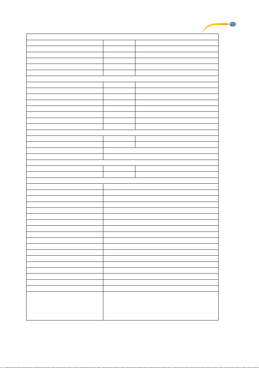
3 Technical specifications
Current measurement DC A
Measuring range
Resolution
Accuracy (of rdg.)
500 μA
0.01 μA
± (1% + 6 digits)
5000 μA
0.1 μA
± (1% + 6 digits)
50 A
0.01A
± (2.5% + 5 digits)
1000 A
0.1 A
± (2.5% + 30 digits)
Current measurement AC A
Measuring range
Resolution
Accuracy (of rdg.)
500 μA
0.01 μA
± (1.5% + 30 digits)
5000 μA
0.1 μA
± (1.5% + 30 digits)
50 A
0.01A
± (2.5% + 30 digits)
1000 A
0.1 A
± (2.8% + 30 digits)
Note: For AC A measurements, the specification of accuracy refers to the range of 5%
to 100% of the measuring range
Voltage measurement DC V
Measuring range
Resolution
Accuracy (of rdg.)
500 Ω
0.01
± (1% + 9 digits)
5 kΩ
0.0001
± (1% + 5 digits)
50 kΩ
0.001
± (1% + 5 digits)
500 kΩ
0.01
± (1% + 5 digits)
5 MΩ
0.0001
± (3% + 10 digits)
50 MΩ
0.001
± (3.5% + 10 digits)
© PCE Instruments
3
Capacitance measurement
Measuring range
Resolution
Accuracy (of rdg.))
500 nF
0.01
± (3.5% + 40 digits)
5000 nF
0.1
± (3.5% + 10 digits)
50 μF
0.001
± (3.5% + 10 digits)
500 μF
0.01
± (3.5% + 10 digits)
5mF
0.0001
± (5% + 10 digits)
Frequency measurement
Measuring range
Resolution
Accuracy (of rdg.)
50 Hz
0.001
± (0.3% + 2 digits)
500 Hz
0.01
± (0.3% + 2 digits)
5 kHz
0.0001
± (0.3% + 2 digits)
50 khz
0.001
± (0.3% + 2 digits)
500 kHz
0.01
± (0.3% + 2 digits)
5 Mhz
0.0001
± (0.3% + 2 digits)
10 MHz
0.001
± (0.3% + 2 digits)
Duty cycle
Measuring range
Resolution
Accuracy (of rdg.))
5% ... 95%
0.1
± (1% + 2 digits) (from the reading)
Pulse width
100 μs ... 100 ms
Frequency
10 Hz ... 10 kHz
Temperature
Measuring range
Resolution
Accuracy (of rdg.))
-100 ... 1000°C / -148 ... 1832°F
0.1
± (1% + 2.5°C / 3.5°F)
General technical data
Conductor diameter
Max. 48 mm / 1.9 in
Display
Two lines 50,000 digits
Continuity test
50 ohms / <50-mA
Diode test
0.3-mA / 2.8V DC
Battery indicator
Battery icon when battery low
Overrange
OL, if measuring range exceeded
Sample rate
2 Hz
Peak detection
>1 ms
Thermocouple
Type K
Fuse
500-mA ceramic quick-acting
AC bandwidth (AC A / AC V)
50 Hz ... 400 Hz
AC measurement
True RMS
Operating conditions
5 ... 40°C / 41 ... 104°F, max. 80% RH at 31°C
Storage conditions
-20 ... 60°C / -4 ... 140°F, max. 80% rh
Power supply
9V block battery
Automatic shutdown
After about 30 minutes
Dimensions (W x H x D)
230 x 76 x 40 mm / 9 x 3 x 1.6 in
Weight
315 g / <1 lb
Safety
IEC 1010-1 (2001):
EN 61010-1 (2001)
CAT III 600V
CAT II 1000V Degree of
pollution 2

© PCE Instruments
4
4 System description
4.1 Device
1. Current clamp
2. Clamp opener
3. Backlight/HOLD key
4. MODE key
5. LCD
6. K-type thermocouple input jack
7. Test lead input jacks
8. Non-contact voltage detector
9. Lamp
10. LED indicator of NCV detector
11. Lamp/ZERO key
12. Rotary function switch
13. MAX/MIN key
14. RANGE/PEAK/thermocouple key
15. Input shutter
4.2 Display
HOLD
Reading held
Auto Power Off active
AUTO
Automatic measurement
range
Peak value held
DC
DC voltage
AC
AC voltage
MAX
Maximum reading
MIN
Minimum reading
Low battery level
ZERO
DCA and CAP zero
mV or V
volts (voltage)
Ω
ohms (resistance)
A
amperes (current)
F
farads (capacitance)
Hz
hertz (frequency)
%
Duty cycle
°C und °F
Temperature unit
T1, T2, T1-T2
Temperature connection 1
Temperature connection 2
Temperature connection 1-2
n, m, µ, M, k
Unit prefixes
Continuity test
Diode test
© PCE Instruments
5
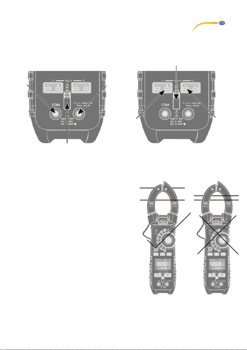
5 Input shutter
The input shutter is a mechanical security element to prevent simultaneous connection of the
thermocouples and of the test leads to avoid accidents. By moving the switch down, the input
jacks for the test leads are unblocked and the jacks for the thermocouples are blocked. By moving
the switch up, the input jacks for the thermocouples are unblocked and the jacks for the test leads
are blocked.
6 Non-contact voltage testing
Turn the rotary function switch to any position to switch on the meter. Now touch the test object
with the measuring tip of the clamp. If the test object carries voltage, the NCV LED will glow.
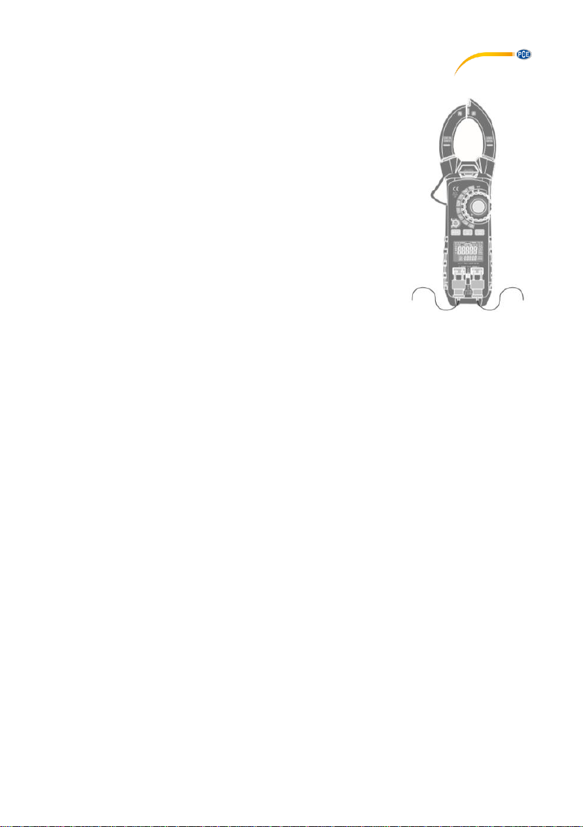
7 AC/DC current measurement
To make current measurements, first remove all test
leads form the meter. Then turn the rotary function
switch to “1000 A“. Now press the MODE key to
choose either AC or DC. Open the clamp with the
clamp opener. Place the clamp around the cable to
be measured (see picture) and close the clamp. If
the displayed reading is below 50 A AC/DC, turn the
rotary function switch to “50 A”.
7.1 Zeroing
To zero the meter, short-press the ZERO key. If you
hear a beep tone, zeroing has been successful.
© PCE Instruments
6
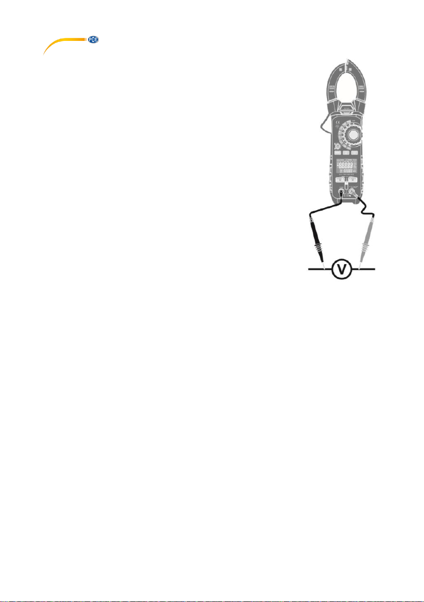
8 AC/DC voltage measurement
To make a voltage measurement, move the input shutter up to unblock
the input jacks. Then turn the rotary function switch to the “V“ position.
Now press the MODE key to select either DC or AC. Now connect the
black test lead to the “COM“ jack and the red test lead to the red jack.
The black jack is for negative connection and the red jack is for
positive connection The voltage value will be displayed directly after
connecting the test leads.

© PCE Instruments
7
9 Resistance / continuity / diode / capacitance measurement
To make a resistance measurement, continuity test, diode test or
capacitance measurement, move the input shutter up to unlock the
input jacks. Turn the rotary function switch to “Ω“. Now press the
MODE key to switch between resistance measurement, continuity
test, diode test and capacitance measurement. Now connect the
black test lead to the “COM“ jack and connect the red test lead to
the red jack.
9.1 Continuity test
When making a continuity test, an audible signal will sound as soon
as the resistance value is <50 Ω.
9.2 Diode test
To test diodes, connect the test leads to the diode now and
remember or write down the displayed reading. Now swap polarity
and compare the new reading to the first reading. The
measurement can be evaluated as follows:
If “OL“ is displayed after both measurements, the diode is defective.
If “OL“ is displayed after one measurement and typical values such
as 0.400 … 1.800 V are displayed after the second measurement,
this means that the diode works. If voltage readings are displayed
after both measurements, this means that the diode is defective. In
this case, the diode will cause a short circuit.
9.3 Capacitance measurement
A short time after connecting the test leads, a farad value will be
displayed. Note that the capacitors are charged during this
measurement. To avoid electric shocks, these should be
discharged after the measurement where needed.
9.4 Resistance measurement
The resistance reading will be displayed immediately when the test leads have been connected.

© PCE Instruments
8
10 Frequency measurement
To make a frequency measurement, move the input shutter up to unlock
the input jacks. Turn the rotary function switch to the “Hz“ position. Now
connect the black test lead to the “COM“ input jack and the red test lead
to the red input jack. Now measure your test object.
11 µA DC/AC current measurement
To make a µA DC/AC power measurement, move the input shutter up to unlock
the input jacks. Turn the rotary function switch to “µA“. Now connect the black
test lead to the “COM“ input jack and the red test lead to the red input jack.
Now measure your test object. The black jack is for negative connection and
the red jack is for positive connection. Make sure the meter is connected in
series to the test object.
© PCE Instruments
9
12 K-type temperature measurement
To make a temperature measurement, move the input shutter down
to unlock the input jacks. Turn the rotary function switch to “TEMP“.
Now connect your K-type thermocouples to the meter, observing
correct polarity. The temperature value will be displayed directly.
With the MODE key, you can now switch between degrees
Fahrenheit and degrees Celsius. With the RANGE key, you can
select which of the connected sensors you want to be displayed. If
you select “T1-T2“, the difference between the two sensors will be
displayed. In the lower line of the display, you can see the sensor
(T1 or T2).
13 Hold readings
To freeze the current measurement value, press the HOLD key. The
display will now show the “HOLD” icon. To unfreeze the reading,
press the HOLD key again. The meter will return to the current measurement.
14 MIN/MAX
Press the MIN/MAX key to start recording. The “MAX” icon will appear in the display. During
MIN/MAX recording, only the highest, lowest and average value will be saved temporarily. All
other readings will be lost. By pressing the MIN/MAX key, you can switch between the minimum,
the maximum and the average value. Press and hold the “MIN/MAX“ key for two seconds to leave
this mode and return to normal measuring mode.
15 Hold peak value
In ACA or ACV mode, press the PEAK key for two seconds to view the peak values of a waveform.
To leave this mode, press the PEAK key for two seconds again.
16 Measurement range
In voltage, resistance, capacitance, frequency and µA current mode, you can select a
measurement range. The standard mode is automatic mode. When this mode is on, the “AUTO“
icon will be displayed. In this mode, the meter selects the measurement range automatically. With
the RANGE key, you can select a measurement range. To re-activate automatic mode, press the
RANGE key for two seconds.
17 LED backlight
To activate the backlight, press the HOLD key for two seconds. The backlight is now activated. It
will automatically be deactivated after 30 seconds.

© PCE Instruments
10
18 Activate / deactivate lamp
To activate the lamp at the clamp, press the Lamp key on the right-hand side of the meter for two
seconds. When the lamp is on, a dual beep tone will sound. To turn off the lamp, press the same
key again for two seconds. A dual beep sound will be audible.
19 Auto Power Off
To save battery power, the meter will turn off automatically after 30 minutes. To turn off the Auto
Power Off function, first turn off the meter. Press and hold the MODE key. Now turn the rotary
function switch to any function to turn on the meter. Now release the MODE key. “APO d“ will now
be displayed. Auto Power Off is now deactivated. To re-activate this mode, just turn off the meter.
20 Battery level indicator
When the battery level is no longer sufficient, the following icon will appear in the display: .
Replace the 9 V block battery. Failure to change the battery can cause incorrect measurements
or even failure of the meter. To replace the battery, open the battery compartment cover at the
rear side of the meter by loosening the screw with a screwdriver. When replacing the battery,
observe correct polarity and make sure that the battery compartment is properly closed after
battery replacement.
21 Replace the fuse
To replace the fuse, turn off the meter and remove all test leads. Then open the battery
compartment. You can now see the fuse below the battery. You can now remove the fuse and
replace it by a new one. The following type of fuse should be used: 500 mA, 660 V F [SIBA 70180-40].

© PCE Instruments
11
22 Warranty
You can read our warranty terms in our General Business Terms which you can find here:
https://www.pce-instruments.com/english/terms.
23 Disposal
For the disposal of batteries in the EU, the 2006/66/EC directive of the European Parliament
applies. Due to the contained pollutants, batteries must not be disposed of as household waste.
They must be given to collection points designed for that purpose.
In order to comply with the EU directive 2012/19/EU we take our devices back. We either re-use
them or give them to a recycling company which disposes of the devices in line with law.
For countries outside the EU, batteries and devices should be disposed of in accordance with
your local waste regulations.
If you have any questions, please contact PCE Instruments.

© PCE Instruments
12
PCE Instruments contact information
Germany France Spain
PCE Deutschland GmbH PCE Instruments France EURL PCE Ibérica S.L.
Im Langel 4 23, rue de Strasbourg Calle Mayor, 53
D-59872 Meschede 67250 Soultz-Sous-Forets 02500 Tobarra (Albacete)
Deutschland France España
Tel.: +49 (0) 2903 976 99 0 Téléphone: +33 (0) 972 3537 17 Tel. : +34 967 543 548
Fax: +49 (0) 2903 976 99 29 Numéro de fax: +33 (0) 972 3537 18 Fax: +34 967 543 542
info@pce-instruments.com info@pce-france.fr info@pce-iberica.es
www.pce-instruments.com/deutsch www.pce-instruments.com/french www.pce-instruments.com/espanol
Germany United Kingdom Italy
PCE Produktions- und PCE Instruments UK Ltd PCE Italia s.r.l.
Entwicklungsgesellschaft mbH Unit 11 Southpoint Business Park Via Pesciatina 878 / B-Interno 6
Im Langel 26 Ensign Way, Southampton 55010 Loc. Gragnano
D-59872 Meschede Hampshire Capannori (Lucca)
Deutschland United Kingdom, SO31 4RF Italia
Tel.: +49 (0) 2903 976 99 471 Tel: +44 (0) 2380 98703 0 Telefono: +39 0583 975 114
Fax: +49 (0) 2903 976 99 9971 Fax: +44 (0) 2380 98703 9 Fax: +39 0583 974 824
info@pce-instruments.com info@industrial-needs.com info@pce-italia.it
www.pce-instruments.com/deutsch www.pce-instruments.com/english www.pce-instruments.com/italiano
The Netherlands China Hong Kong
PCE Brookhuis B.V. PCE (Beijing) Technology Co., Limited PCE Instruments HK Ltd.
Institutenweg 15 1519 Room, 6 Building Unit J, 21/F., COS Centre
7521 PH Enschede Zhong Ang Times Plaza 56 Tsun Yip Street
Nederland No. 9 Mentougou Road, Tou Gou District Kwun Tong
Telefoon: +31 (0)53 737 01 92 102300 Beijing, China Kowloon, Hong Kong
info@pcebenelux.nl Tel: +86 (10) 8893 9660 Tel: +852-301-84912
www.pce-instruments.com/dutch info@pce-instruments.cn jyi@pce-instruments.com
www.pce-instruments.cn www.pce-instruments.cn
United States of America Turkey
PCE Americas Inc. PCE Teknik Cihazları Ltd.Şti.
711 Commerce Way suite 8 Halkalı Merkez Mah.
Jupiter / Palm Beach Pehlivan Sok. No.6/C
33458 FL 34303 Küçükçekmece - İstanbul
USA Türkiye
Tel: +1 (561) 320-9162 Tel: 0212 471 11 47
Fax: +1 (561) 320-9176 Faks: 0212 705 53 93
info@pce-americas.com info@pce-cihazlari.com.tr
www.pce-instruments.com/us www.pce-instruments.com/turkish
 Loading...