

Page 1
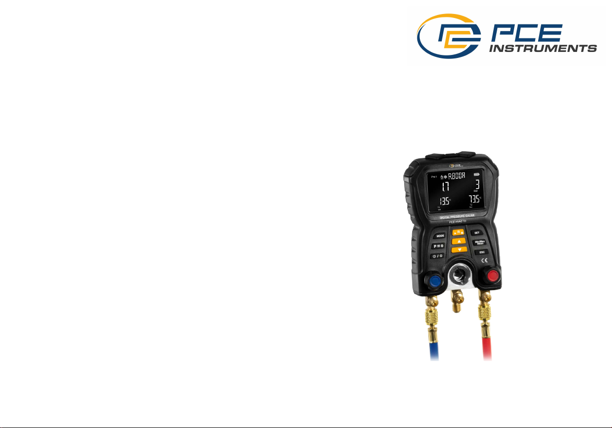
Operation Instructions for
Manifold Tester
PCE-HVAC 10
Page 2

Table of Contents
Summary
Cautions
Product Structures
Button Functions
Initial Operation
An Introduction to Display
Description of Settings
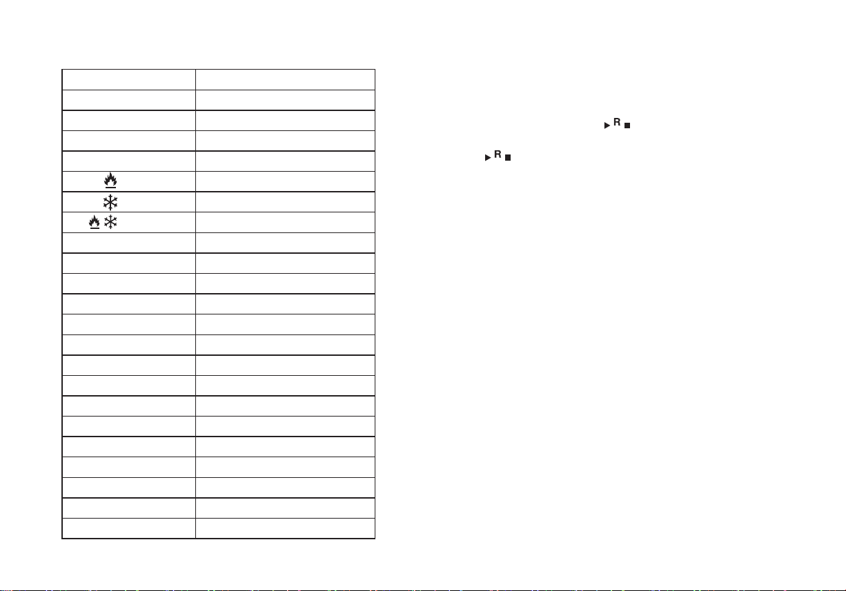
Description of Symbols
Routine Measurement
Leakage Test
Product Specification
Disposal
Contact details
1
1
2
4
6
7
9
12
13
13
14
15
16
Summary
This product is the integration of functions of pressure measurement and
temperature measurement. It is mainly used for leakage detection,
refrigerant charging, troubleshooting and maintenance of the refrigeration
system.
Cautions
To ensure the proper use of this product, please read the operation
instructions carefully:
1. Never disassemble or refit this product personally without authorization.
2. If the hose is damaged, please change it in a timely manner.
3. Do not drop or impact the instrument to avoid damage.
4. The measuring instrument can only be used by qualified and approved
personnel.
5. If this product lies idle for long, please take out the battery to avoid battery
leakage and corrosion.
6. Refrigerant gas will do hazard to the environment, so it is required to
ensure that it will comply with the local environmental regulations when
using it.
7. If there is any failure in the instrument, stop using it and contact the
supplier or manufacturer in time.
8. Do not discard the waste batteries at will, but send them to the specified
collection points for waste batteries.
9. Please evaluate whether the measuring object or environment is safe, and
note the safety standards in your measuring areas.
10. The instrument is suitable for the measurement of most non corrosive
refrigerants, water and alcohol media. The instrument may not be used in
explosion-proof areas.
1
Page 3
Product structures
11
⑩
⑨
②①
12
③
④
⑤
⑥
⑦
⑧
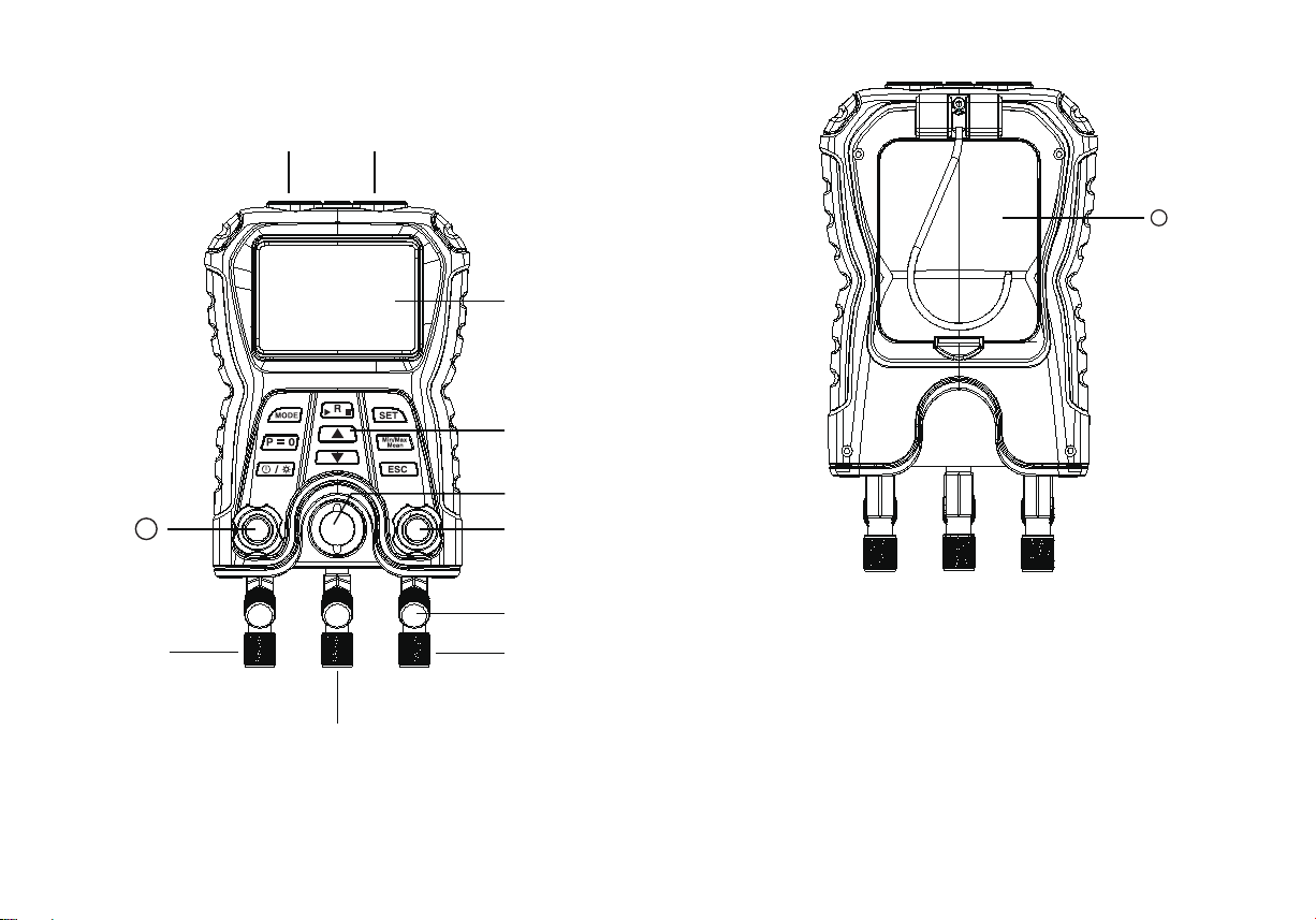
① Terminal T1 temperature clamping port
② Terminal T2 temperature clamping port
③ Display screen
④ Button
⑤ Liquid view mirror (used to observe the flow of refrigerants)
2 3
Page 4
① Terminal T1 temperature clamping port
② Terminal T2 temperature clamping port
③ Display screen
④ Button
⑤ Liquid view mirror (used to observe the flow of refrigerants)
⑥ High pressure end control valve: loosen it counterclockwise, turn on the
value for ventilation, tighten it clockwise, and there is no air ventilation after
the valve is turned off.
⑦ Liquid filling pipe support
⑧ High pressure end connector
⑨ Liquid filling end connector: used to connect the refrigerant bottles
⑩ Low pressure end connector
Loosen it counterclockwise, turn on the value for ventilation, tighten it
clockwise, and there is no air ventilation after the valve is turned off.
Battery compartment
Buttons Functions
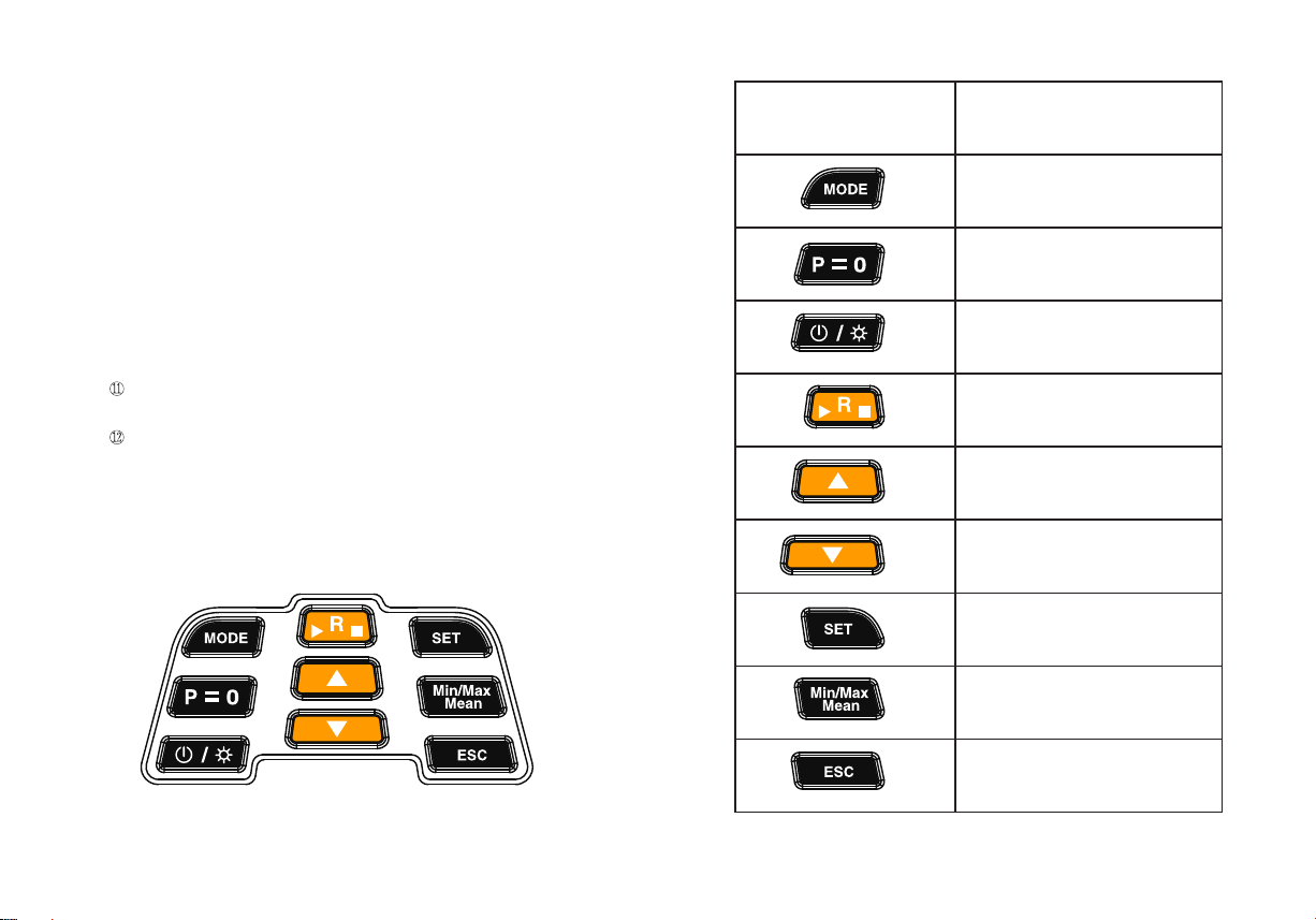
Go to or exit the leakage
test interface
Clear pressure readings
Power on/off
Backlight on/off
Go to the refrigerant selection interface;
Start/Stop leakage test
Up button: to switch interfaces;
Change parameters during setup
Button functions
Down button: to switch interfaces;
Change parameters during setup
Go to the setting interface
View maximum/minimum/
mean values
Return to the measurement
interface
4 5
Page 5
Iitial operation
Power on/off
Long press the “ ” button for power on or of
f.
Clear pressure
Before connecting the hose, clear the pressure readings: Turn on the value,
and press “P=0” button for clearance.
Backlight
Shortly press the “ ” button to activate backlight, and press it once
again to deactivate backlight.
Mounting the battery
Open the battery cover. Install 4 AA alkaline batteries. Note the polarity.
They may not be mounted wrongly. After battery installation, cover the
battery cover.
An Introduction to display interface
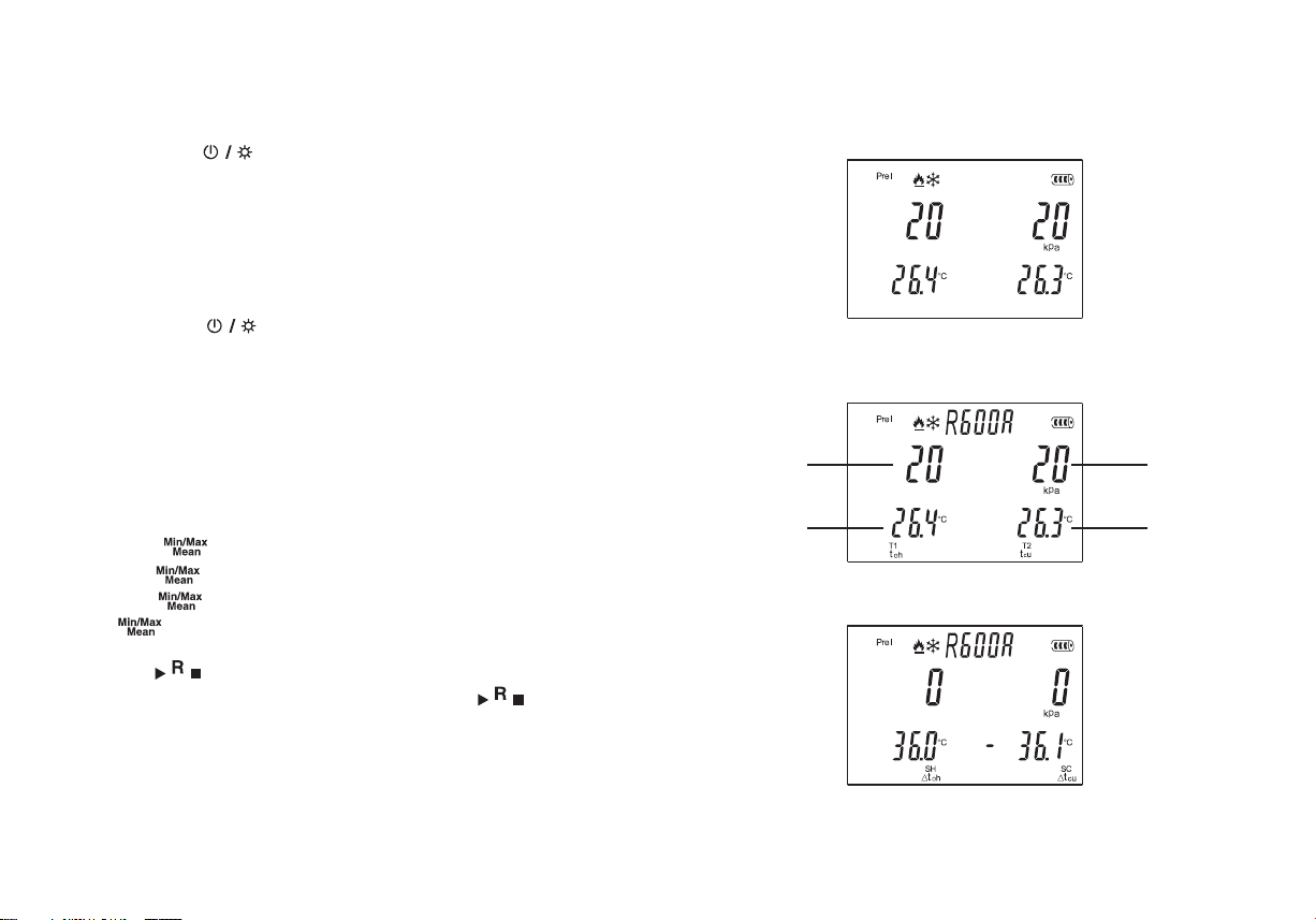
If no refrigerant has been chosen, the following interface is displayed by
default when powered on
If one of refrigerants is selected, the following interface is displayed by
default when powered on
Evaporating
pressure
Condensing
pressure
Maximum, minimum and mean values
Press the “ ” button to display the maximum value → continue to
press the “ ” button to display the minimum value → continue to
press the “ ” button to display the mean value → continue to press
the “ ” button to exit (or press “ESC” button to q
Select refrigerants
Press the “ ” button to go to the refrigerant selection interface. Press
the “▲” or the “▼” button to switch refrigerants. Press the “ ” button
again to return to the measurement interface.
6 7
uit).
T1 probe
temperature value
Press the “▼” button to switch to the over cooling and overheating display
interface, as shown in the figure below:
T2 probe
temperature
value
Page 6
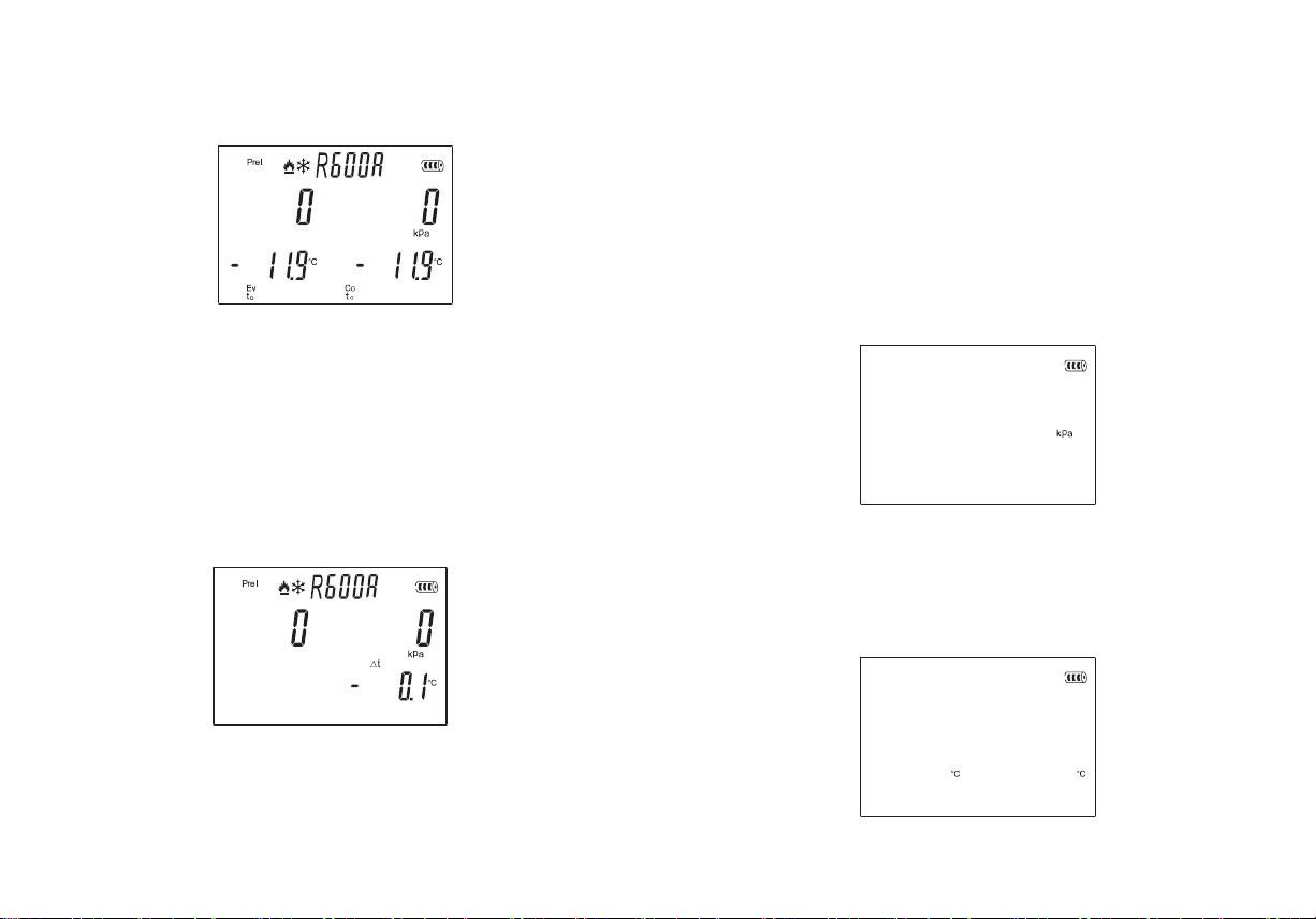
Continue to press the “▼” button to switch to the evaporating temperature
and condensing temperature display interface.
Pressure is displayed at the upper part of the screen, and the evaporating
temperature and condensing temperature are displayed at the lower part of
the screen.
Continue to press the “▼” button to switch to the temperature difference
display interface.
Description of settings
Continuously press the “SET” button 6 times, with the display in turn:
pressure unit setting interface → temperature unit setting interface →
relative/absolute pressure setting interface → Air pressure setting interface
→ refrigerating/heating mode setting interface → automatic power off function
setting interface. Finally, press the “ESC” button to quit the setting interface.
1. Setting pressure units
From the pressure unit setting interface, press the “▲ ” button or “ ▼” button
to switch the pressure units. There are four pressure units in all: kpa, Mpa,
psi and bar
2. Setting temperature units
From the temperature unit setting interface, press the “▲ ” button or “ ▼” bu
tton to switch temperature units. There are 2 temperature units in all: ℃ and ℉.
Δt=T2-T1
8 9
Page 7

3. Setting relative/absolute pressure
From the relative/absolute pressure setting interface, press the “▲ ” button
or “▼ ” button to select the relative pressure measurement mode or absolute
pressure measurement mode.
Absolute pressure: pressure value by adding air pressure.
Relative pressure: pressure value minus air pressure.
If the relative pressure measurement mode is chosen: according to the
selected pressure unit, prel or psig is displayed at the left upper cornerof the
screen.
If the absolute measurement is chosen: according to the selected pressure
measurement unit, pabs or psia is displayed at the left upper corner of the
screen.
4. Air pressure setting interface
There is difference in air pressure in different areas. The user will make
adjustments to air pressure at the place where he or she is currently located.
From the air pressure setting interface, press the “▲ ” button or “▼ ” button
to adjust the air pressure value.
5. Setting the refrigerating/heating modes
From the refrigerating/heating mode setting interface, press the “▲” button or
“ ▼” button to select one of the modes. There are three modes in all: hot
pump mode, refrigerating mode, and automatic mode.
6. Setting automatic power off functions
From the automatic power off function setting interface, press “▲ ” button or
“▼ ” button, select “on” to turn on the automatic power off function, and
select “off” to turn off the automatic power off function. When the automatic
power off function is turned on: if you do not press the button within 20
minutes, it will be automatically shut down.
10 11
Page 8
Description of Symbols Routine measurement
Symbols
T1
T2
prel or psig
pabs or psia
max
min
mean
p=0
Δt
Δtoh
SH
Δtcu
SC
to
Ev
tc
Co
toh
tcu
Meaning
Number of temperature probe
Number of temperature probe
Relative pressure
Absolute pressure
Hot pump mode
Refrigerating mode
Auto mode
Maximum value
Minimum value
Mean value
Clear pressure readings
T2-T1
Overheat
Evaporating pressure
Over cooling
Condensing pressure
Refrigerant’s evaporating
temperature
Refrigerant’s evaporating pressure
Refrigerant’s condensing
temperature
Refrigerant’s condensing pressure
Actually measured temperature at
T1 terminal (evaporating temperature)
Actually measured temperature at
T2 terminal (condensing temperature)
12 13
1. Connect 2 temperature clamps respectively to the temperature probe
connector of the instrument.
2. Power on
3. Select refrigerants: press the “ ” button to enter the refrigerant selection
interface. Press the “▲ ” button or “▼ ” button to switch refrigerants. Press
the “ ” button once again to return to the measurement interface.
4. Select the measurement mode (please refer to “Description of Settings”
for the operation method)
5. Connect the high pressure end and the low pressure end under an
ambient pressure.
6. If the reading is not zero without pressure input, please press the “P = 0”
button to clear the pressure readings.
7. Turn off the control valve before connecting the refrigerant hose:
Connect the
8. Connect the liquid filling pipe to the system.
9. Input pressure to the measuring instrument.
10. Read the readings. Press the “▲ ” button or “▼” button to be able to
switch to other measurement interfaces.
Leakage test
This function is used for leakage test in refrigeration or hot pump system.
Leakage analysis is performed by system pressure over a period of time.
1. Press the “P = 0” button to clear the pressure readings (clearance if there
is no pressure input).
2. Use a hose to connect the high pressure end of the instrument to
the system.
3. Press the “mode” button to switch to the leakage test interface, as shown
in the figure below:
Page 9
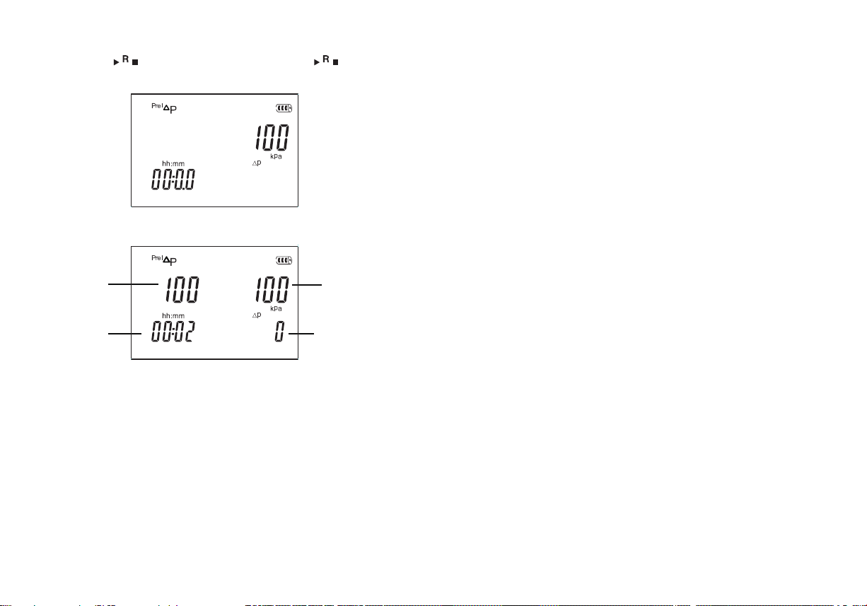
4. Press the “ ” button to start the test, and press the “ ” once
again to stop the test.
5. The test duration depends on the system tested.
Pressure before
start of test
Test duration
Real-time pressure
after start of test
Real-time pressure
value after start
minus pressure value
before start of test
Product specification
Pressure measuring range (relative pressure: -100 to 6000Kpa/-0.1 to
6Mpa/-14.5 to 870psi / -1 to 60bar
Overload pressure: 6500Kpa/6.5Mpa/940psi/65bar
Pressure accuracy: ±0.5%FS
Pressure resolution: 1Kpa, 0.01bar, 0.1psi, 0.001Mpa (0.01Mpa during
negative pressure)
Temperature measuring range: -10-200℃/14-392℉
Temperature accuracy: ± (1℃+1digit);
Temperature resolution: 0.1℃/0.1℉
Optional refrigerants (83 kinds): R11, R12, R123, R124, R125, R1270,
R13, R134A, R14, R141b, R142b, R143A, R152A, R170, R21, R218,
R22, R227E, R23, R236E, R245C, R245, R290, R32, R401A, R401b,
R401C, R402A, R402b, R403A, R403b, R404A, R405A, R406A, R407A,
R407b, R407C, R407d, R407E, R408A, R409A, R409b, R41, R410A,
R410b, R411A, R411b, R412A, R413A, R414A, R414b, R415A, R415b,
R416A, R417A, R418A, R419A, R420A, R421A, R421b, R422A, R422b,
R422C, R422d, R423A, R424A, R425A, R426A, R427A, R428A, R50,
R500, R501, R502, R503, R504, R507A, R508A, R508b, R509A, R600,
R600A, R717
Operating temperature: 0 to 45℃
Storage temperature: -20 to 60℃
Ambient humidity: 10%RH to 90%RH
Power supply: 4 AA batteries
Dimension: 204mm×116mm×65mm
Accessories: tool box, hose (each
in red, yellow and blue), Operation
Instructions, 4 AA alkaline batteries,
temperature clamps x2
14
15
Page 10
Contact
If you have any questions, suggestions or technical problems, please do not
hesitate to contact us. You will find the relevant contact information at the end of
this user manual.
Disposal
For the disposal of batteries in the EU, the 2006/66/EC directive of the
European Parliament applies. Due to the contained pollutants, batteries must not
be disposed of as household waste. They must be given to collection points
designed for that purpose.
In order to comply with the EU directive 2012/19/EU we take our devices back. We
either re-use them or give them to a recycling company which disposes of the
devices in line with law.
For countries outside the EU, batteries and devices should be disposed of in
accordance with your local waste regulations.
If you have any questions, please contact PCE Instruments.
PCE Instruments contact information
Germany
PCE Deutschland GmbH
Im Langel 26
D-59872 Meschede
Deutschland
Tel.: +49 (0) 2903 976 99 0
Fax: +49 (0) 2903 976 99 29
[email protected]
www.pce-instruments.com/
deutsch
United Kingdom
PCE Instruments UK Ltd
Trafford House
Chester Rd, Old Trafford
Manchester M32 0RS
United Kingdom
Tel: +44 (0) 161 464902 0
Fax: +44 (0) 161 464902 9
[email protected]
www.pce-instruments.com/
english
The Netherlands
PCE Brookhuis B.V.
Institutenweg 15
7521 PH Enschede
Nederland
Telefoon: +31 (0)53 737 01 92
[email protected]
www.pce-instruments.com/
dutch
France
PCE Instruments France EURL
23, rue de Strasbourg
67250 Soultz-Sous-Forets
France
Téléphone: +33 (0) 972 3537 17
Fax: +33 (0) 972 3537 18
[email protected]
www.pce-instruments.com/french
Italy
PCE Italia s.r.l.
Via Pesciatina 878 / B-Interno 6
55010 Loc. Gragnano
Capannori (Lucca)
Italia
Telefono: +39 0583 975 114
Fax: +39 0583 974 824
[email protected]
www.pce-instruments.com/
italiano
United States of
America
PCE Americas Inc.
1201 Jupiter Park Drive, Suite 8
Jupiter / Palm Beach
33458 FL
USA
Tel: +1 (561) 320-9162
Fax: +1 (561) 320-9176
[email protected]
www.pce-instruments.com/us
Spain
PCE Ibérica S.L.
Calle Mula, 8
02500 Tobarra (Albacete)
España
Tel. : +34 967 543 548
Fax: +34 967 543 542
[email protected]
www.pce-instruments.com/
espanol
Turkey
PCE Teknik Cihazları Ltd.Şti.
Halkalı Merkez Mah.
Pehlivan Sok. No.6/C
34303 Küçükçekmece İstanbul Türkiye
Tel: 0212 471 11 47
Faks: 0212 705 53 93
[email protected]
www.pce-instruments.com/
turkish
Denmark
PCE Instruments Denmark
ApS Birk Centerpark 40
7400 Herning
Denmark
Tel.: +45 70
kontakt@pceinstruments.com www.pceinstruments.com/dansk
30 53 08
16
17
 Loading...