

Page 1
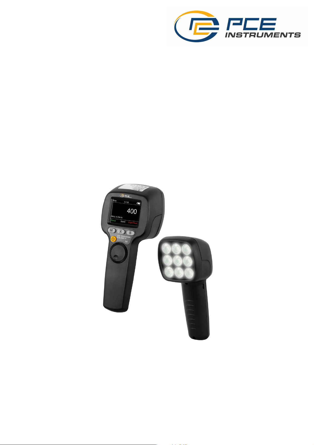
User Manual
PCE-DSX 10
Stroboscope
Page 2

Introduction
This instrument is a new LED light source that flashes at a certain frequency. When observing a high-speed
rotating or moving object with this instrument, the flashing frequency of the LED lamp is adjusted to be
close to or synchronized with the rotation or movement speed of the measured object. Although the measured
object is moving at a high speed, it seems to be moving slowly or stationary. Therefore, the instrument will
detect the rotation speed of the object or the surface quality or movement condition of the high-speed moving
object.
This instrument uses the latest imported LED as light source, which has many advantages over traditional
Xenon lamp, such as high brightness, long life, reliable triggering and so on. The latest digital frequency
synthesis technology is applied in this instrument, and the flash frequency output is more accurate, stable
and reliable. The stroboscopic output adjustment uses a 360 degree rotating dial and a combination rate shift
switch. It can rotate left or right without limits and adjust the stroboscopic rate quickly or slowly. The
numerical increase or decrease operation is lightweight and convenient. This instrument uses LCD as display.
The reading is clearer than previous generation products, and the display information of operation interface
is intuitive. This instrument is compact, light, easy to carry, easy to hold and read, and has a beautiful
appearance. Its biggest feature is that the speed measurement accuracy is in the leading level of similar
instruments in global. Because of the non-contact speed measurement, the operation is simple and easy, and
it has the unique superiority of flash speed measurement.
Therefore, this instrument is especially suitable for rotating speed measurement of motors, fans, pumps, gears,
product quality detection of high-speed production line, product vibration diagnosis and so on. It can be used
in Heating Ventilation Air Conditioning (HVAC), printing, paper making, textile, medicine, light industry,
mechanical processing and other industries.
Main Technical Parameters
1. Range: 60 - 999999 rpm
2. Speed measurement accuracy: 0.001%
3. Illumination: 1500 LUX
4. Display: LCD display
5. Power supply: 7.4V/2200mA lithium battery
6. Power consumption: When working ≤ 0.2 W, it can work for 8 hours continuously and standby time is 3
months.
7. Operating environment temperature: -10℃ - 55℃
8. Size: 210 × 90 × 57 (mm)
9. Weight: 320g (with battery)
Product illustrations
As the following diagram shows
1. Stroboscopic rate adjustment rotary dial
2. X Stroboscopic multiplier/Zero button
3. S Phase adjustment button
4. Stroboscopic rate increase/decrease digital bit rate display
5. Current remaining power display
Page 3
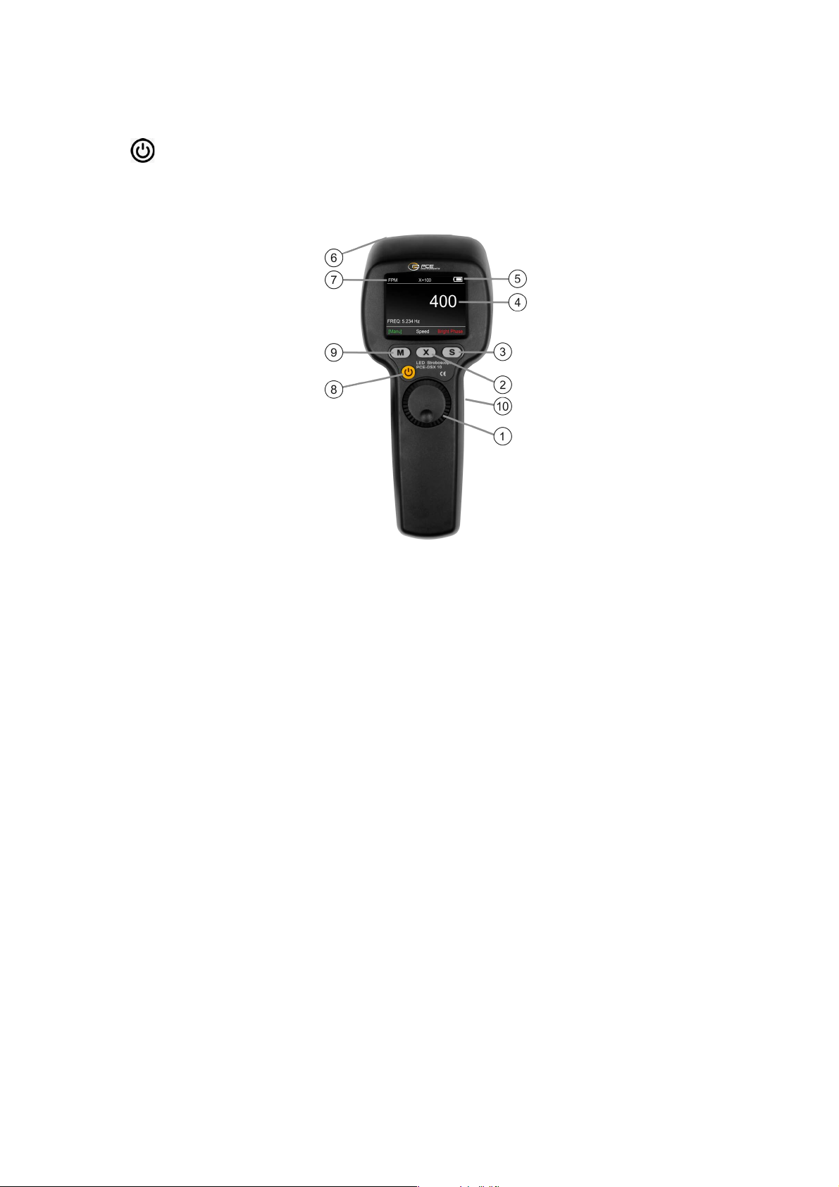
6. LED Flash Projection Light Source
7. Rotation speed, frequency or brightness indication display
8. Power switch button
9. M Mode switch button
10. USB port
Operational Steps
The front of the instrument has an LCD display, four button keys and an adjusting dial.
Display:
Displays the current speed (hertz/brightness), multiplier, and battery level during the measurement.
Power key buttons:
After pressing the power key, the power is on and the instrument works; Press again, turn off, and the
instrument will save the last speed data;
Phase button key:
Switch to phase key (S) to rotate the dial left and right, and the measured object will rotate slowly at a certain
speed, so as to observe the working conditions of the object at various angles during operation.
Storage function
Press the M key to the speed measurement function, and press and hold the phase key (S) for 3 seconds to
enter the storage function.
As shown in the figure
Page 4
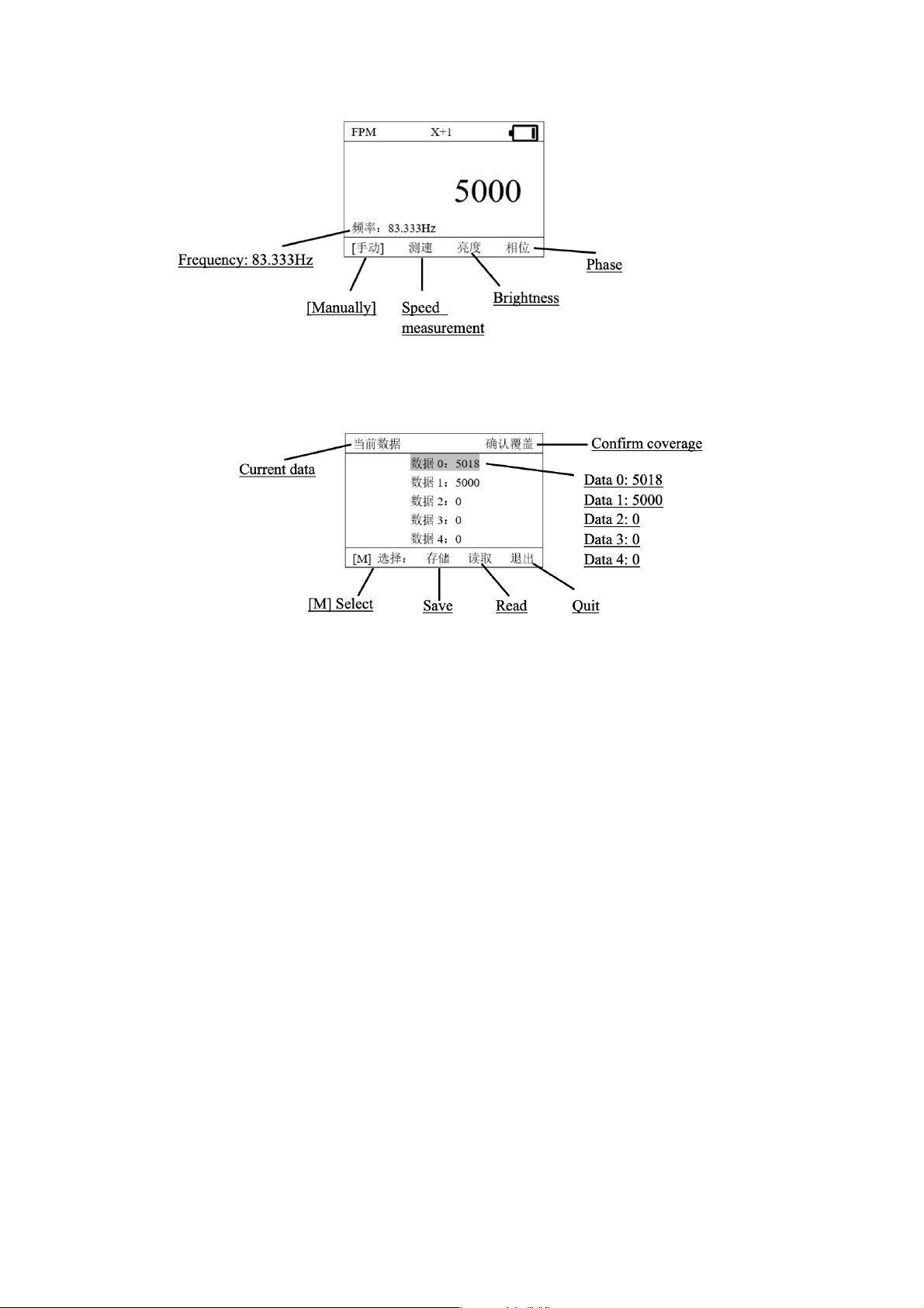
Figure 1: Starting up
Figure 2: Storage function
Multiplier button key:
Pressing the multiplier key/zero button, the display will show X+1, X+10, X+100 or Xmeter 2X/2 (default
power-on multiplier is X1). Turn the dial one grid and the output will increase or decrease by 1, 10 or 100
rpm accordingly. Hold on the multiplier/zero button for 3 seconds to clear the numbers on the display.
Mode switch button:
Press the mode switch button and FPM (rotational speed), Hz (frequency) or (brightness) will be displayed
on the display. Turn the dial to adjust the FRM (rotational speed) or (brightness) accordingly.
Adjusting dial:
Turn the adjusting dial in FPM mode. When the multiplier on the display is X1, the dial rotates one grid and
the output increases or decreases by one turn/minute accordingly. When the multiplier on the display is X10,
the dial rotates one grid and the output increases or decreases by 10 rpm accordingly. When the multiplier
on the display is X100, the dial rotates one grid and the output increases or decreases by 100 rpm accordingly.
Please choose the appropriate multiplier so that the operator can find the target more quickly.
Turn the adjustment dial in (brightness) mode. The dial rotates one grid and the output increase or decrease
by one brightness unit. The maximum brightness is 100 and the minimum brightness is 0.
Page 5

1. Speed measurement
(1) Mark the near-center part of the measured object or identify the existing feature marker (suitable for
asymmetric markers).
(2) Press the power key and the instrument starts to work. The display shows the last saved test speed of
the instrument.
(3) If the speed of the measured object is unknown, you should estimate its approximate range, aim the
flash at the target, start with high rotation. Then, you need to adjust the multiplier, turn the adjusting
dial and quickly reduce the test speed. Once the image appears, adjust the smaller multiplier and turn
the adjusting dial to increase or decrease to fine tune until the first stable single image appears. The
reading on the display is the number of turns per minute of the measured object.
(4) If the speed range of the measured object is known, you can adjust the instrument to the corresponding
test speed first. Then you need to adjust the multiplier to X1, and use fine tuning method; When a
stable single image first appears, the reading on the display is the number of turns per minute of the
measured object.
2. Dynamic Observation
Method is same as 1. When the first single image appears, use fine-tune to measure speed and to make the
flash frequency slightly different from the speed. In this way, the single image is not stationary, but rotates
at a slow speed. The direction and speed of rotation of the image are controlled by fine-tune adjustments.
Depending on the need, in order to make the measured object rotate more slowly, the difference between
flash frequency and rotation speed will be smaller and vice versa will be faster.
3. Discrimination of rotation direction
Method is same as 1. When the first single image appears, use fine-tune to measure speed and to make the
flash frequency slightly different from the speed. In this way, the image is not stationary but rotates slowly.
The direction of rotation of the image is the direction of rotation of the object.
Rules for Speed Measurement
The flash tester actually provides a pulsed light source with an adjustable frequency and a very short duration.
If the fan rotates at a speed of 1,300 rpm, the flash frequency is 1,300 rpm. Since these two speeds are equal
(synchronous), it is clear that the blade of the fan will be in the same position as the last flash. So, with the
help of human visual persistence, the blade of the fan does not seem to move at all. That is, when the flash
frequency of the instrument is equal to the rotation frequency of the measured object, the rotating object
appears to be stationary which presents a still image. In this case, the flash frequency is the speed of the
object. This is the principle of flash speed measurement.
Assume that the speed of the fan is still 1300 rpm and the speed of the flash changes to 1301 rpm. Because
the speed of the flash is faster than the speed of the fan, the blade of the fan does not reach the position of
the last flash and lags slightly for each flash. This phenomenon visually shows that the fan is turning
backwards slowly. Conversely, when the flash is 1299 times per minute, the human eye will see that the fan
is turning forward slowly. That is, when the flash frequency of the instrument is slightly different from the
rotation frequency of the measured object, a flash image appears much slower than the actual rotation speed,
and it is a true copy of the high-speed movement. With this phenomenon, high-speed motion can be carefully
observed and measured.
Page 6

Discriminating rotation speed
In fact, when looking for the speed of the measured object, under the illumination of a pulsed flash light
source, the stroboscopic image of a moving object appears more complex. A single image or any ghost image
does not appear only at one flash frequency. Therefore, when measuring speed with this instrument, if the
speed range is known, place the flash frequency within this range to look for it. If the speed range is unknown,
start from the highest point to lower. In this way, the number of ghost image becomes smaller and smaller
until the first time a single stable image appears, which indicates the true measured speed. When the flash
frequency continues to decrease, although a single image will appear, the image is dark and the contrast is
small. In this case, you need to pay more attention in order to prevent errors.
To make it easier to understand the discrimination of true images and rotating speeds: a single stable, clear
and bright image shows the true measured speed. If the single image is dark and the contrast is small, the
image is not realistic.
Power supply and charging of instruments
The instrument is powered by a lithium battery, which is placed inside the instrument and connected to the
mainboard by a connector. When the power is sufficient, the LCD display of the instrument shows a full grid
(4 grids). After a period of use, the power will gradually reduce. When the instrument shows blank grid, the
power is insufficient. At this time, please stop using the instrument and charge the instrument in time. In
order to prolong the usage time and the life of the instrument, please use the matching charger accompanying
the instrument to charge.
When charging the instrument, first plug the charger output into the charging socket of the instrument, then
plug the charging unit of 220V AC into the 220V AC socket. At this time, the indicator on the charger is red
and the whole charging process is automatic charging. When the battery is full, the indicator on the charger
is green and you can unplug the power plug and cut off the power supply. Please note that overcharging for
too long will affect the battery life.
When using this instrument for the first time, the battery capacity should be sufficient, clear and reach the
nominal capacity after several cycles of cyclic charging and discharging. This will help to prolong the life of
the battery. If you do not use the instrument for a long time, open the back cover of the instrument and unplug
the battery connection to the mainboard, or remove the battery.
Cautions
1. Do not knock or squeeze the instrument with heavy objects
2. Do not place the instrument in wet places
3. Do not place the instrument in an environment where the temperature is above 55 degrees C
4. Do not place the instrument in places with too much acid or salt mist
Accessories
1 x stroboscope PCE-DSX 10
1 x USB cable
1 x operating instructions
 Loading...