

Page 1

PCE Americas Inc.
711 Commerce Way
Suite 8
Jupiter
FL-33458
USA
From outside US: +1
Tel: (561) 320-9162
Fax: (561) 320-9176
info@pce-americas.com
PCE Instruments UK Ltd.
Units 12/13
Southpoint Business Park
Ensign way
Hampshire / Southampton
United Kingdom, SO31 4RF
From outside UK: +44
Tel: (0) 2380 98703 0
Fax: (0) 2380 98703 9
info@pce-instruments.com
www.pce-instruments.com/english
www.pce-instruments.com
Manual
Hardness Tester
PCE-DDA 10
PCE-DDD 10
PCE-DDO 10
Version 1.0
Date of creation: 04.08.2015
Date of last change: 27.09.2017
Page 2

Manual
2
Contents
1 Delivery content ...................................................................................................... 3
2 Introduction ............................................................................................................. 4
3 Safety notes ............................................................................................................. 4
4 Specification ............................................................................................................ 5
4.1 Application fields ......................................................................................................................... 5
4.2 Applications ................................................................................................................................ 5
4.3 General technical data ................................................................................................................ 5
5 System description ................................................................................................. 6
5.1 Basic part .................................................................................................................................... 6
5.2 Keyboard .................................................................................................................................... 6
5.2.1 Power/Return ................................................................................................................................. 6
5.2.2 OK .................................................................................................................................................. 6
5.2.3 UP .................................................................................................................................................. 6
5.2.4 Down .............................................................................................................................................. 6
5.3 Interface ...................................................................................................................................... 6
6 Measuring ................................................................................................................ 7
6.1 Specimen .................................................................................................................................... 7
6.2 Measure ...................................................................................................................................... 7
7 Menu ......................................................................................................................... 8
7.1 Menu structure ............................................................................................................................ 8
7.2 Menus operation ......................................................................................................................... 8
7.3 Calibration................................................................................................................................... 9
7.4 Test setup ................................................................................................................................... 9
7.4.1 Test Mode ...................................................................................................................................... 9
7.4.2 Test Times ..................................................................................................................................... 9
7.4.3 Tolerance ..................................................................................................................................... 10
7.4.4 Grubbs error ................................................................................................................................. 10
7.4.5 Workpiece .................................................................................................................................... 10
7.4.6 Dwell Time ................................................................................................................................... 10
7.5 System Setup ........................................................................................................................... 10
7.5.1 Date/Time ..................................................................................................................................... 10
7.5.2 Backlight Time .............................................................................................................................. 11
7.5.3 Key Sound .................................................................................................................................... 11
7.5.4 Alarm Sound ................................................................................................................................ 11
7.6 Memory ..................................................................................................................................... 11
7.6.1 Browse A to Z ............................................................................................................................... 11
7.6.2 Browse Z to A ............................................................................................................................... 11
7.6.3 Delete Select ................................................................................................................................ 11
7.6.4 Delete All ...................................................................................................................................... 11
8 Maintain .................................................................................................................. 12
8.1 Generally .................................................................................................................................. 12
8.2 Recharging ............................................................................................................................... 12
8.3 Reset ........................................................................................................................................ 12
9 Software ................................................................................................................. 12
9.1 Installation ............................................................................................................................... 12
9.2 File upload ............................................................................................................................... 12
Page 3

Manual
3
9.3 Query and search ................................................................................................................... 14
9.4 Delete data .............................................................................................................................. 14
9.5 Print .......................................................................................................................................... 15
9.6 Data export .............................................................................................................................. 15
9.7 Close software ........................................................................................................................ 15
10 Contact ................................................................................................................... 16
10.1 PCE Instruments UK ................................................................................................................ 16
10.2 PCE Americas .......................................................................................................................... 16
1 Delivery content
• rubber hardness tester
• standard calibration plate
• user maual
• Mini USB cable
• charger / AC adaptor
• storage box
The software can be downloaded here: https://www.pce-instruments.com/english/download-win_4.htm.
Page 4

Manual
4
2 Introduction
Thank you for purchasing a durometer of the PCE-DD series from PCE Instruments.
The durometers are mainly used to measure the hardness of hard rubber and hard plastic, such as:
thermoplastic, hard resin, flooring, bowing and especially for on-site hardness measurement of rubber
and plastic products.
The principle used to measure hardness is based on measuring the resistance force of the penetration of
a indenter into the test material penetration (max. 2,5 mm) can be converted to hardness reading on a
scale with 100 units. The formula is “HD=100-(L/0,025)”. According to this formula, the types Shore
hardness is relative to the displacement of the pressed indenter. Through measuring the displacement of
the pressed indenter, the types Shore Hardness can be calculated.
3 Safety notes
Please read this manual carefully and completely before you use the device for the first time. The device
may only be used by qualified personnel and repaired by PCE Instruments personnel. There is no
warranty of damages or injuries caused by non-observance of the manual.
Only authorized charger is allowed to be applied to this, otherwise it will be damaged permanently.
Any part of this can’t be immersed in water or be exposed to rain, otherwise it will be damaged
permanently
Origin package is need for long time storage.
Temperature: -30 … +80 °C / Relative Humidity: 5 … 95 % RH
The Battery should be charged fully before first using
The device may only be used in approved temperature range
The opening of the case should only be done by qualified personnel of the PCE Instruments.
The instrument should never be placed with the user interface (e.g. keyboard side on a table)
You should not make technical changes on the device
The appliance should only be cleaned with a damp cloth / use only pH-neutral cleaner
This user's handbook is published from PCE Instruments without any guarantee.
We expressly point to our general guarantee terms, they can be found in our general terms of business.
If you have any questions please contact PCE Instruments.
Page 5

Manual
5
4 Specification
4.1 Application fields
A/C
B/D
o/do/oo
Strut diameter of the
indenter (mm)
2,25 ±0,1
1,25 ±0,1
2,38 ±0,08
Top plane diameter of
the indenter (mm)
0,79 ±0,03
-
Top sphere radius (mm)
-
0,1 ±0,01
1,19 ±0,05
Top cone angle of the
indenter
(35 ±0,25)°
(30 ±0,5)°
-
4.2 Applications
TYPE
Applications
A
Soft vulcanized rubber, natural rubber, nitriles, thermoplastic elastomers,
flexible polyacrylics and thermosets, wax, felt and leathers
C
Medium-hard rubber, thermoplastic elastomers, medium-hard plastics and
thermoplastics
D
Hard rubber, thermoplastic elastomers, harder plastics and rigid
thermoplastics
B
Moderately hard rubber, thermoplastic elastomers, paper products and
fibrous materials
OO
Soft rubber, thermoplastic elastomers, very soft plastics and thermoplastics,
medium-density textile windings
O
Extremely soft rubber, thermoplastic elastomers, sponge, extremely soft
plastics and thermoplastics, foams, low-destiny textile windings, human and
animal tissue
DO
Moderately hard rubber, thermoplastic elastomers and very dense textile
windings
4.3 General technical data
Measure Range
0 … 100 H
Measure accuracy
≤ ±1 H
Data memory
500 readings
Power
3,6 V rechargeable Ni-MH battery
Working time
About 20 hrs (by one recharging)
Recharging time
About 3 hours
Work temperature
0 … +50 °C
Work humidity
20% … 85 % RH
Storage
-30 … +80 °C / 5 … 95 % RH
Dimensions
153 x 50 x 29 mm (main body)
Weight
Approx. 170 g
Conforms to
GB/T 531.1, ISO7619-1, ASTM D 2240
Page 6

Manual
6
5 System description
5.1 Basic part
Digital Durometer Main body: 1 x
Charger: 1 x
Standardized thickness block: 1 x
5.2 Keyboard
5.2.1 Power/Return
By pressing this button, the durometer will be power on.
By long time pressing this button, the durometer will be
power off. By pressing this button, the screen will return
to the upper level menu.
5.2.2 OK
Under the measure interface, it will enter the menu interface by pressing this button. Under the
menu interface, it will enter the next menu interface. In addition, it is the confirmation button
under function selection or parameters setting interface.
5.2.3 UP
Under the menu interface, the selection will be shifted up by pressing this button. Under
parameters setting interface, the value will increase by pressing this button.
5.2.4 Down
Under the menu interface, the selection will be shifted down by pressing this button. Under
parameters setting interface, the value will decrease by pressing this button. Under some
parameters setting interface, the selection will be moved down by pressing this button.
5.3 Interface
The large and high resolution LCD is applied to this durometer, so this durometer has the advantage of
fully information display and easy to read etc.
1
Battery level
2
Hardness value
3
Range
4
Average value
5
Test times
6
Current times
7
Test mode: Indicating AVE, Max,
MAX AVE
Page 7

Manual
7
6 Measuring
6.1 Specimen
1. The surface of the specimen shall be flat and parallel over an area to permit the presser foot to
contact the specimen over an area having a radius of at least 6 mm from the indenter point.
2. The Specimen shall be suitably supported to provide for positioning and stability.
3. The specimen shall be at least 6 mm in thickness unless it is known that results equivalent to the
6 mm values are obtained with thinner specimen.
The lateral dimensions of the specimen shall be sufficient to permit measurements at least 12 mm from
any edge.
6.2 Measure
1. To press the indenter on the surface of specimen and make sure the presser foot is contact
closely to it.
2. When data is stable, the buzzer will make a sound and the value will be shown until the next
measuring.
Test mode: maximum average value mode
Hardness value measured: 58,1 H
Current statistic times: 5
The measured number: 2
Current average value: 57,8 H
Range: 0,7 H
Multi-point measuring will be realized repeating above steps.
Page 8

Manual
8
7 Menu
7.1 Menu structure
Menu
Calibration
Test Setup
Test mode
Test times
Tolerance
Grubbs error
Workpiece
Dwell Time
System Setup
Date / Time
Backlight Time
Key Sound
Alarm Sound
Memory
Browse select A to Z
Browse select Z to A
Browse select
Delete All
Printing Setup
Auto Print
Print Items
Print selected
Print All
Information
7.2 Menus operation
In test status, pressing button “ ” to enter menus. When selected a menu item, pressing “ ” to enter.
After set up some parameter, pressing “ ” to confirm.
Select menu items. In the digital settings, pressing the “ ” can change the value, pressing the “ ” can
change the set item or digital.
Pressing “ ” can return to the previous menu until to the test interface. Or cancel the earlier setup.
Page 9

Manual
9
7.3 Calibration
The durometer can be calibrated by hard flat plate, standard thickness
block or other rubber whose hardness is known.
1. To press indenter on the flat plate, standard thickness block or the
rubber whose hardness is known. Keeping the presser foot
contact the samples closely for a while to stabilize, the LCD
shows the hardness value.
2. Input the theory value (calibration value). If the flat plate is
applied, input “100”. W hen standard thickness block is applied,
please enter 50. If the rubber is applied, please enter the rubber’s
hardness.
3. To press “ ” to confirm the calibration. Or to press “ ” to
abort the calibration.
7.4 Test setup
Under Test Setup, Test Mode, Test Times, Tolerance, Grubbs Error,
Workpiece, Dwell Time can be set.
7.4.1 Test Mode
There are three kinds of mode: average value mode (AVE), maximum
value mode (MAX) and maximum average value mode (MAX-AVE),
1. AVE: During one sampling process, the durometer will record 20
values and calculate the average value of this 20 value
automatically. The average value will show on the screen. Under
this mode, the statistic time can be set. After one measure
process is finished, the durometer will calculate the average value
and Range of the data until now automatically. If the statistic time is meet, the last average value
will be saved as the measure result.
2. MAX: During one sampling process, the durometer will record 20
values automatically and take the maximum value as the current
result. Under this mode, the statistic times can’t be set.
3. MAX.AVE: During one sampling process, the durometer will
record 20 values automatically and take the maximum value as
the current result. Under this mode, the statistic times setting can
be set. After one measure process is finished, the durometer will
calculate the average value and Range of data until now automatically. The average value of
maximum value of every measuring will be calculated and this value will be taken as the last
result
7.4.2 Test Times
The statistic times can be set under this menu. The maximum statistic times
setting is 9.
Page 10

Manual
10
7.4.3 Tolerance
Under this menu, the tolerance limit can be set. When the measuring data
is exceed the setting value, the icon of “!” will be showed on the LCD and it
will flash. If the alarm function is turn on, the durometer will make the alarm
sound.
7.4.4 Grubbs error
Under this menu, the Grubbs error handling
can be set to on or off. (Grubbs error handling
is available only under the average mode and
maximum average mode). If the Grubbs error
handling function is turn on, the Grubbs error
analysis will be applied to the current group
when a statistic group is formed (the measure
times meet the setting time) and the gross
error data will be taken as invalided data to be abandoned during the calculating of average value and
Range. If the auto-print function is turn on, a symbol of “!” will be marked after the gross error data.
7.4.5 Workpiece
When several samples is need to be measured, the samples can be coded. The coded range is 00 … 99.
When the date saved, the sample code saved too. The samples number corresponding to the data can
be printed. It also can be looked up during browsing.
7.4.6 Dwell Time
When Dwell Time is set not “0”, the hardness value is captured for a period
of time. This way is specialized by some standards. Now a countdown clock
is displayed on LCD.
7.5 System Setup
Under System Setup, the date/time, backlight time, on or off of key
sound, on or off of alarm sound can be set.
7.5.1 Date/Time
Under this menu, year, month, day, hour, minute, second can be set.
Page 11
Manual
11
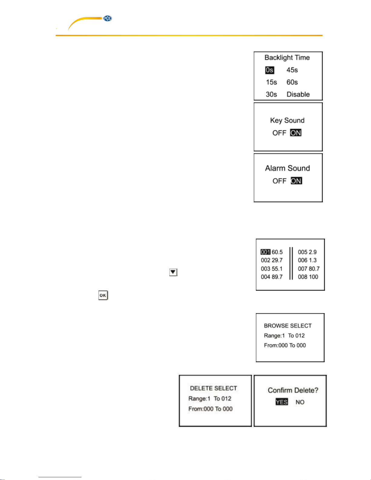
7.5.2 Backlight Time
Under this menu, the continued lighting time of the backlight can be set.
0s: The backlight will be turned off all times.
15s, 30s, 45s, 60s: The backlight will be turn off when there
is no operation for longer than the set.
Disable: The backlight will light all the time.
7.5.3 Key Sound
The Key sound can be turn on or off.
7.5.4 Alarm Sound
If this function is set as on, the duro meter will make a sound of alarm when
the data is exeed the tolerance limit.
7.6 Memory
This durometer can storage 500 group data at most (one group data include: one hardness value, the
date/time/sample code). If 500 group data have been saved, no more data can be saved, “M Full” will be
displayed. You need to delete some or all data for future storage.
7.6.1 Browse A to Z
The first page data will be show when enter this menu (8 data per page). It
will turn to the next page by pressing button “ “.
The measure date/time/sample code of the selected data can be show by
pressing button “ ”.
7.6.2 Browse Z to A
The last page data will be show when enter this menu.
7.6.3 Delete Select
The range of data to be deleted should be setup under this menu.
7.6.4 Delete All
The prompt window will be pushed out under
this menu. All data will be deleted by
selection of “Yes” and this operation will be
aborted by selection of “No”.
Page 12

Manual
12
8 Maintain
8.1 Generally
1. This durometer should avoid shock or heavy pressure and can’t be exposed to high-intensity
magnetic field, high humidity or oil environment.
2. Because the print paper is heat sensitive paper, the paper should avoid high temperature and
direct light. If the paper data need to be stored for long time, please make a copy in time.
3. When there are any abnormalities, please don’t try to dissemble or adjust any fixed parts. You
should fill the warranty card and contact our maintenance department or maintenance agency
authorized by our company. Normally, the durometer will not stay in the maintenance department
over one week.
8.2 Recharging
The durometer will be recharged by the packaged charger. The durometer will not be auto power on
during recharging. The charging status will show in the measuring interface by hand power on. The
moving of the battery level icon line indicates it is charging now. If the icon is filled by all line, it means the
charging process is finished. If the power is low, the battery level icon will flash to prompt to be recharged
in time.
8.3 Reset
Durometer reset: If the software abnormal is happened, the durometer will reset automatically. Hardware
reset: The durometer can be reset by the hardware reset under the crash. The reset button is local in the
hole of the back shell.
9 Software
9.1 Installation
Start the installation by double-clicking on the file „setup_vXX.exe“ and follow the instructions of the
installation wizard.
9.2 File upload
1. Connect the durometer to the PC via the mini USB cable.
2. In the „Control Area“, select the COM port assigned by your PC and assign an index name in the
„Condition Area“ to be able to differentiate between several data records.
3. To be able to start the data upload, the upload mode has to be activated. To do so, click on the
„Upload Data To PC(U)“ button.
4. Within the durometer menu, navigate to „Memory“, select „Upload Data“. Confirm your selection
with the key on the device.
5. After a few seconds, the data will appear in the software.
Page 13

Manual
13
Then click on the “Upload
Data” button.
First assign an index name to
be able to differentiate
between several data records
Page 14

Manual
14
9.3 Query and search
1. If you only need the search function, set the needed values in the „Condition Area“ (see image
below) and then click on „Inquiry“
2. In the „Date Area“, you can limit the measured data to a certain date or period. You can select
whether you would like to regard the day of measurement („Detection“) or the upload date („Upload“).
Select „Detection“ or „Upload“, depending on your requirement and set the start („From“) and end
date („To“).
3. The index name must be assigned manually before each data upload. It helps to differentiate
between different data records and makes it easier to search for certain data.
4. Via „No. From“ and „No. To“, you can narrow down how many saved measurements are included in
the search.
5. Via „Max value“ and „Min Value“, you can limit your search to a certain range of measurement
values.
9.4 Delete data
To delete data, you must first select the data to be deleted from the displayed list. When you have
selected all data, click on „Delete“ and confirm the deletion by clicking on „Ok“.
Page 15

Manual
15
9.5 Print
After limiting the data by clicking on the „Inquiry“ button, you can print all data from the chart by clicking
on the „Print“ button.
9.6 Data export
You can export your data (which are in the chart at that time) into a different file format
at any time. Two different file formats (Excel or CSV file) can be selected. Click on the
corresponding button „Save As …“ to save the data.
9.7 Close software
To close and exit the software, you can either click on the „Exit“ button or on the „X“ on the upper, righthand side of the window. A dialogue box will then appear, asking you to confirm.
Page 16

Manual
16
10 Contact
If you have any questions about our range of products or measuring instruments please contact PCE
Instruments.
10.1 PCE Instruments UK
By post:
PCE Instruments UK Ltd.
Units 12/13 Southpoint Business Park
Ensign Way, Southampton
Hampshire
United Kingdom, SO31 4RF
By phone:
02380 987 035
10.2 PCE Americas
By post:
PCE Americas Inc.
711 Commerce Way
Suite 8
Jupiter
33458 FL
USA
By phone:
561 320 9162
 Loading...