

Page 1
PCE Americas Inc.
711 Commerce Way
Suite 8
Jupiter
FL-33458
USA
From outside US: +1
Tel: (561) 320-9162
Fax: (561) 320-9176
[email protected]
PCE Instruments UK Ltd.
Units 12/13
Southpoint Business Park
Ensign way
Hampshire / Southampton
United Kingdom, SO31 4RF
From outside UK: +44
Tel: (0) 2380 98703 0
Fax: (0) 2380 98703 9
www.pce-instruments.com/english
www.pce-instruments.com
Manual
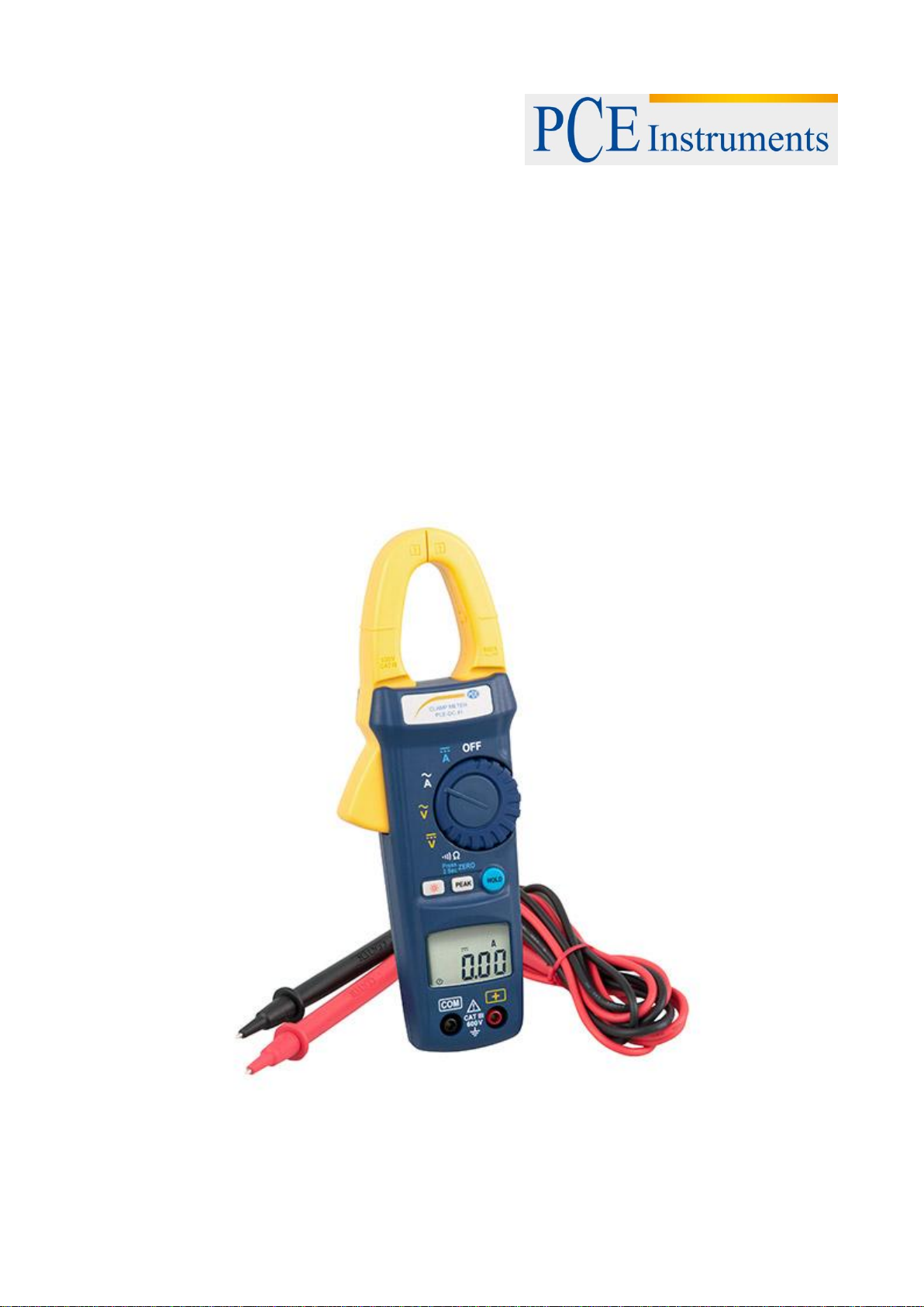
AC/DC Clamp Meter PCE-DC 41
Version 1.1
Date of creation: 07.07.2015
Date of last change: 05.08.2015
Page 2

Manual
Content
1 Introduction ............................................................................................................. 3
2 Safety notes ............................................................................................................. 3
2.1 Warning symbols ........................................................................................................................ 3
2.2 Safety instructions ...................................................................................................................... 3
3 Specifications .......................................................................................................... 4
3.1 General ....................................................................................................................................... 4
3.2 Electrical ..................................................................................................................................... 5
4 System description ................................................................................................. 6
4.1 Display ........................................................................................................................................ 6
4.2 Front and rear ............................................................................................................................. 7
4.3 Key functions .............................................................................................................................. 7
4.3.1 HOLD function ................................................................................................................................ 7
4.3.2 PEAK function ................................................................................................................................ 7
4.3.3 Zero function .................................................................................................................................. 7
4.3.4 Backlight function ........................................................................................................................... 7
5 Instructions .............................................................................................................. 8
5.1 Measurement .............................................................................................................................. 8
5.1.1 AC voltage measurement .............................................................................................................. 8
5.1.2 DC voltage measurement .............................................................................................................. 8
5.1.3 AC current measurement ............................................................................................................... 9
5.1.4 DC current measurement ............................................................................................................... 9
5.1.5 Resistance measurement ............................................................................................................ 10
5.1.6 Continuity test with buzzer ........................................................................................................... 10
5.2 Battery replacement ................................................................................................................. 11
5.3 Maintenance ............................................................................................................................. 11
5.4 Cleaning.................................................................................................................................... 11
6 Contact ................................................................................................................... 12
6.1 PCE Instruments UK ................................................................................................................ 12
6.2 PCE Americas .......................................................................................................................... 12
2
Page 3
Manual
1 Introduction
Thank you for purchasing a PCE-DC 41 from PCE Instruments.
This instrument is highly versatile in power system maintenance as it has several functions. It is not only
very reliable in measuring power, it can also measure voltage, current and continuity at high accuracy.
Measurement results are easily readable from the 4-digit LC display with backlight. The device’s special
features are its Peak Hold and Data Hold functions, its Auto Zero function as well as an Auto Power Off
function which turns off the meter after 30 minutes of inactivity. The instrument comes with batteries, a
test lead, a carrying case and an instruction manual.
2 Safety notes
2.1 Warning symbols
Attention! Please refer to instruction manual.
Dangerous voltage may be present at terminals.
Double insulation.
2.2 Safety instructions
Please read this manual carefully and completely before you use the device for the first time. The device
may only be used by qualified personnel and repaired by PCE Instruments personnel. There is no
warranty of damages or injuries caused by non-observance of the manual.
- The device may only be used in the approved temperature and humidity range.
Operating conditions: 0 … 40 °C (32 … 104 °F); ˂70 % RH
Storage conditions: -10 … 60 °C (14 … 140 °F); ˂80 % RH
- Inspect the device as well as the test leads before each use. If there is any visible damage, do not use
the device.
- Make sure that the main function dial is in the correct position before each measurement.
- Do not carry out any resistance or continuity tests on a live power system.
- Do not apply voltage between the test terminals or a test terminal to ground exceeding the maximum
limit as specified in this manual.
- Keep your fingers behind the protection ring when using the test lead for measurement.
- To ensure high accuracy, replace the battery whenever the icon appears.
- The case should only be opened by qualified personnel of PCE Instruments.
- The instrument should never be placed with the user interface facing an object (e.g. keyboard side on a
table).
- You must not make any technical changes to the device.
- The appliance should only be cleaned with a dry cloth. / Do not use any abrasives or solvents.
This manual is published by PCE Instruments without any guarantee.
We expressly point to our general guarantee terms which can be found in our general terms of business.
If you have any questions please contact PCE Instruments.
3
Page 4
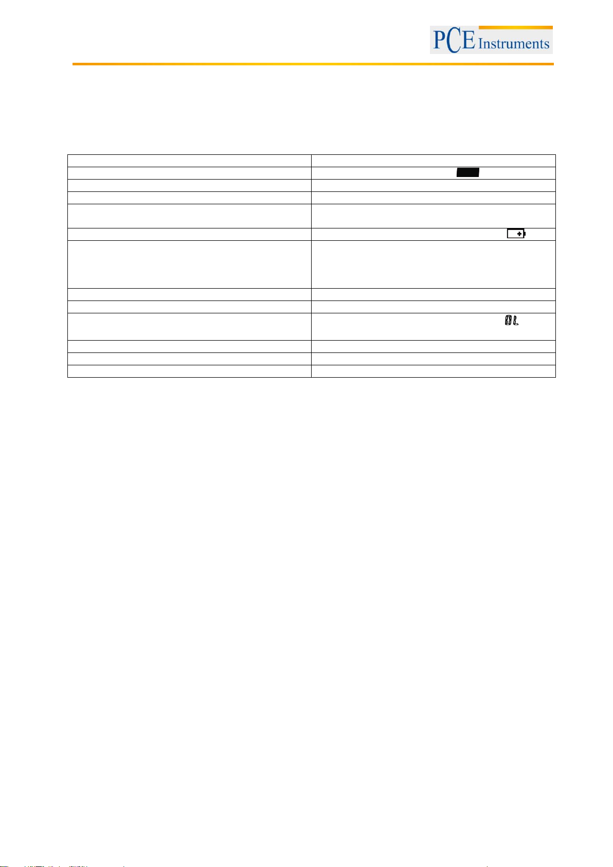
Display
4- digit LCD, maximum reading 6200
Polarity
negative signal is indicated by icon
Sampling rate
3 times/s
Power supply
2 x 1.5 V AAA batteries
Battery life
approx. 50 hours (without buzzer and backlight
function)
Battery level indication
insufficient battery voltage is indicated by icon
Auto Power Off
after 30 minutes of inactivity to save battery
consumption; function can be disabled by pressing
and holding the HOLD key after an Auto Power Off
before the meter is turned on again.
Operating conditions
0 … 40 °C (32 … 104 °F); ˂70 % RH
Storage conditions
-10 … 60 °C (14 … 140 °F); ˂80 % RH
Overload indication
when signal exceeds maximum limit, the icon
appears
Maximum clamp opening
diameter 25 mm
Dimensions
210 x 62 x 36 mm
Weight
273 g with battery
3 Specifications
3.1 General
Manual
4
Page 5
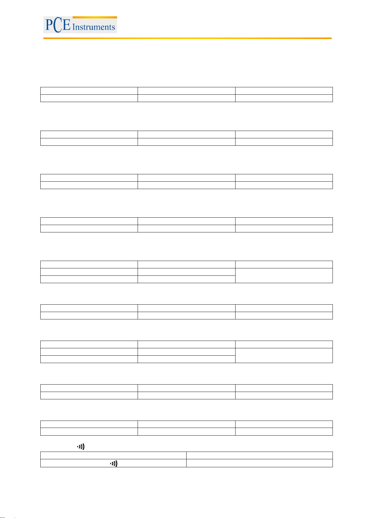
Range
Resolution
Accuracy
600 V
0.1 V
±1 % + 2 digits
Range
Resolution
Accuracy
600 V
0.1 V
±1.5 % + 8 digits
Range
Resolution
Accuracy
600 V
0.1 V
±1.2 % ±5 digits (50 … 500 Hz)
Range
Resolution
Accuracy
600 V
0.1 V
±1.7 % + 10 digits
Range
Resolution
Accuracy
60 A
0.01 A
±2 % + 5 digits
600 A
0.1 A
Range
Resolution
Accuracy
600 A
0.1 A
±2.5 % + 8 digits
Range
Resolution
Accuracy
60 A
0.01 A
±2.0 % ± 5 digits (50 … 60 Hz)
±3.0 % + 5 digits (60 … 500 Hz)
600 A
0.1 A
Range
Resolution
Accuracy
600 A
0.1 A
±2.5 % + 10 digits
Range
Resolution
Accuracy
1000 Ω
0.1 Ω
±1 % + 2 digits
Range
Buzzer function
˂40 Ω
3.2 Electrical
Direct voltage
Input impedance: 1 MΩ
Direct voltage (peak model)
Input impedance: 1 MΩ
Alternating voltage
Input impedance: 1 MΩ
Alternating voltage (peak model)
Manual
Input impedance: 1 MΩ
Direct current
Direct current (peak model)
Alternating current
Alternating current (peak model)
Resistance (Ω)
Continuity
5
Page 6
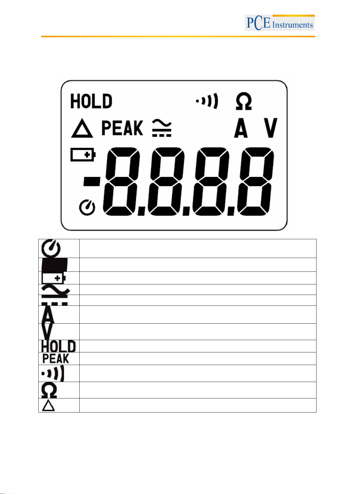
Auto Power Off indication
Polarity indication
Battery level indication (low battery)
Alternating-current source indication
Direct-current source indication
Current measurement indication
Voltage measurement indication
Data Hold indication
Peak data indication
Continuity test indication
Resistance measurement indication
Zero measurement indication
4 System description
4.1 Display
Manual
6
Page 7
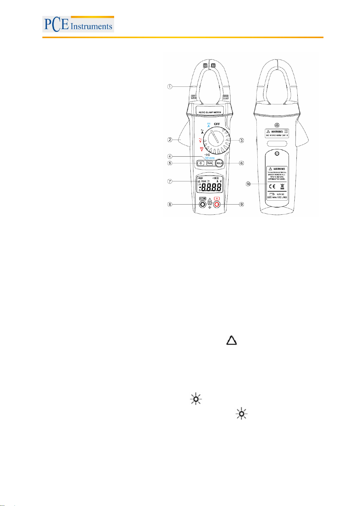
4.2 Front and rear
1 Current sensing clamp
2 Lever to open clamp
3 Dial for function selection
4 PEAK key
5 Backlight key
6 HOLD key
7 LC display
8 COM input terminal
9 Positive input terminal
10 Battery compartment
Manual
4.3 Key functions
4.3.1 HOLD function
You can freeze the current value in the display by pressing the HOLD key. To deactivate this function,
press the HOLD key once again.
4.3.2 PEAK function
When you press the PEAK key, the PEAK icon will appear in the display. The highest value will be
displayed and frozen in the display. This value is updated anytime a higher value is measured. To return
to normal mode, press the PEAK key again.
4.3.3 Zero function
When you press and hold the PEAK key for at least 2 seconds, the icon will be shown. This means
that the zero function is activated, i. e. that the reading is reset to zero. To return to normal mode, press
the PEAK key again.
4.3.4 Backlight function
You can turn on the backlight function by pressing the key. The backlight is a yellow light which will
shine for 15 seconds when activated. To turn off this function, press the key again.
7
Page 8
5 Instructions
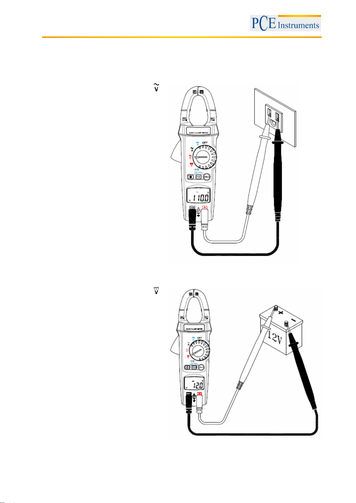
Switch the main function selector to .
Connect the red test lead to the + terminal
and the black test lead to the COM terminal.
Touch the test circuit with the tips of the test
leads and read the result which will appear in
the LCD.
Switch the main function selector to .
Connect the red test lead to the + terminal
and the black test lead to the COM terminal.
Touch the test circuit with the tips of the test
leads and read the result which will appear in
the LCD.
5.1 Measurement
5.1.1 AC voltage measurement
Manual
5.1.2 DC voltage measurement
8
Page 9
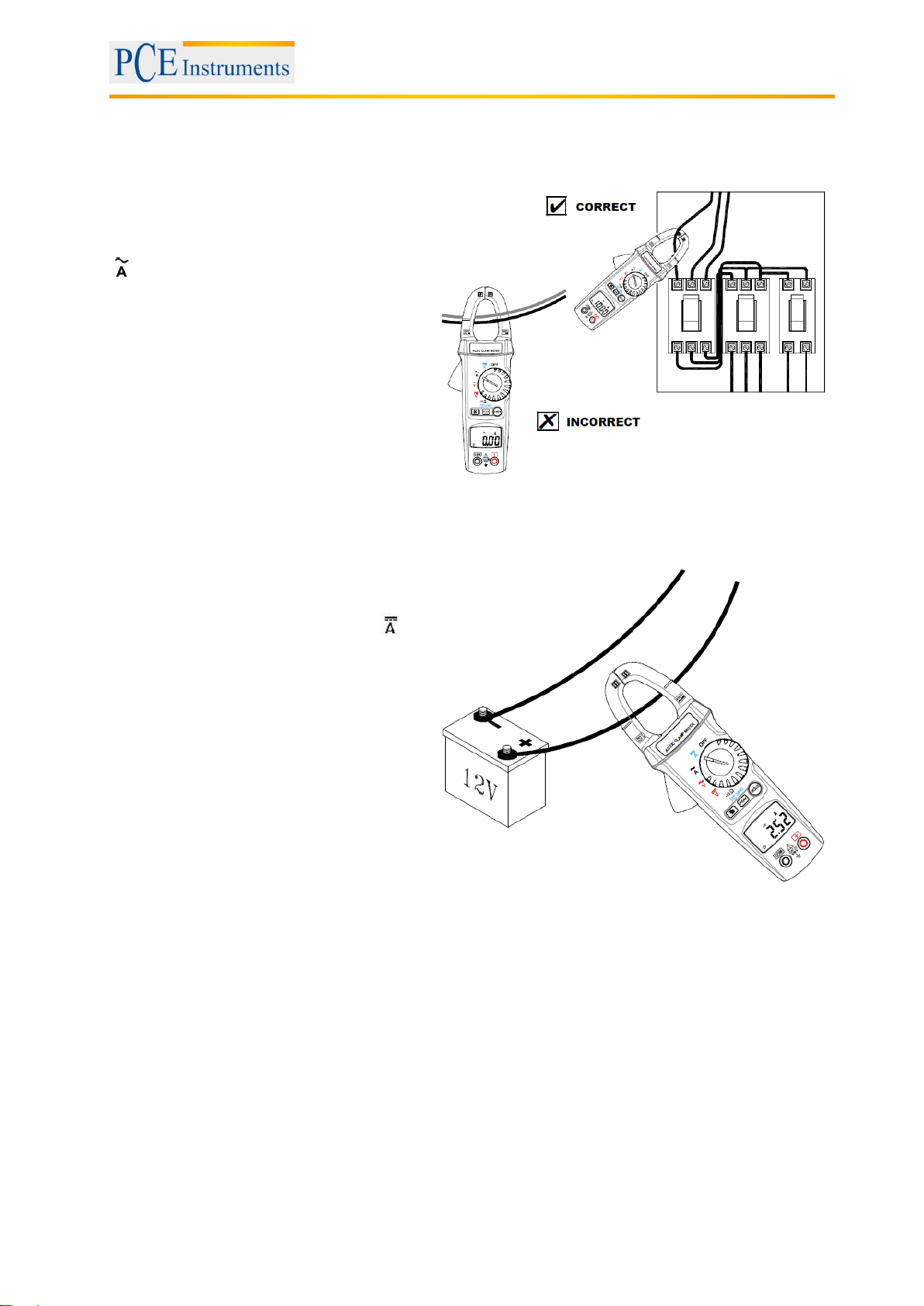
For safety reasons, it is recommended to
disconnect the test leads from the meter
before carrying out this measurement.
Then switch the main function selector to
. Open the clamp by pushing the lever
and insert the cable to be measured into
the hole. When the cable is kept at the
centre, this will ensure most accurate
results. Close the clamp and read the
result from the LCD. It might occur that the
result is hard to read. In this case, press
the HOLD key and read the result at a
later stage.
For safety reasons, it is recommended to
disconnect the test leads from the meter
before carrying out this measurement.
Switch the main function selector to .
Open the clamp by pushing the lever and
insert the cable to be measured into the
hole. When the cable is kept at the centre,
this will ensure most accurate results.
Close the clamp and read the result from
the LCD. It might occur that the result is
hard to read. In this case, press the HOLD
key and read the result at a later stage.
5.1.3 AC current measurement
Manual
5.1.4 DC current measurement
9
Page 10
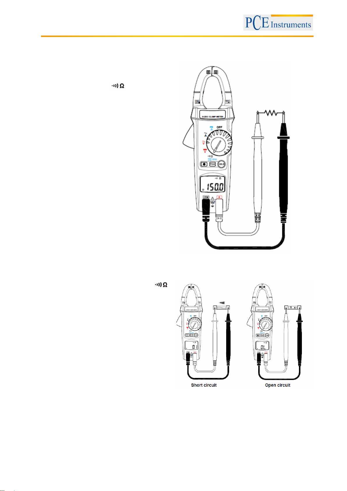
5.1.5 Resistance measurement
Before taking a resistance measurement, make
sure that the power is cut off from the circuit and
that all capacitors are discharged. Then switch the
main function selector to . Connect the red
test lead to the + terminal and the black test lead to
the COM terminal. Touch the points to be tested
with the tips of the test leads and read the result
which will appear in the LCD.
Switch the main function selector to .
Connect the red test lead to the + terminal and
the black test lead to the COM terminal. Place the
tips of the test leads at the points where you wish
to carry out the continuity test. If the resistance is
below 40 Ω, the beeper will sound continuously.
Manual
5.1.6 Continuity test with buzzer
10
Page 11
Manual
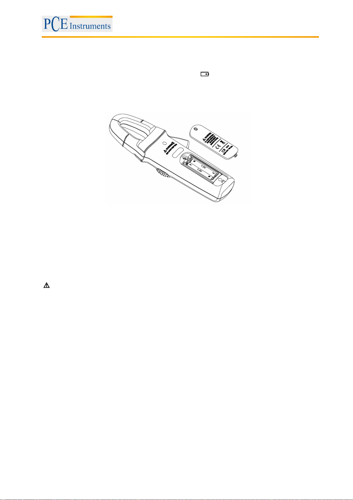
5.2 Battery replacement
When the battery voltage drops below a sufficient level, the icon will appear in the display. When this
happens, please replace the battery.
Before doing so, switch the function selector to OFF and disconnect the test leads. Use a screwdriver to
open the battery compartment cover. Replace the used batteries with two new 1.5 V AAA batteries. Close
the battery compartment cover and fasten the screw.
For the disposal of batteries, the 2006/66/EC directive of the European Parliament applies. Due to the
contained pollutants, batteries must not be disposed of as household waste. They must be given to
collection points designed for that purpose.
In order to comply with the EU directive 2012/19/EU we take our devices back. We either re-use them or
give them to a recycling company which disposes of the devices in line with law.
If you have any questions, please contact PCE Instruments.
5.3 Maintenance
Warning!
Before opening the meter, disconnect both test leads and close the cover.
Caution!
To avoid contamination or static damage, do not touch the circuit board without proper static protection.
- When you know that you will not use the device for a longer period of time, take out the batteries and
store it in a cool, dry place.
- Repairs or maintenance not described in this manual should only be carried out by qualified personnel.
5.4 Cleaning
Wipe the case with a dry cloth on a regular basis. Do not use any abrasives or solvents.
11
Page 12

Manual
6 Contact
If you have any questions about our range of products or measuring instruments please contact PCE
Instruments.
6.1 PCE Instruments UK
By post:
PCE Instruments UK Ltd.
Units 12/13 Southpoint Business Park
Ensign Way, Southampton
Hampshire
United Kingdom, SO31 4RF
By phone:
02380 987 035
6.2 PCE Americas
By post:
PCE Americas Inc.
711 Commerce Way
Suite 8
Jupiter
33458 FL
USA
By phone:
561 320 9162
12
 Loading...