

Page 1
© PCE Instruments
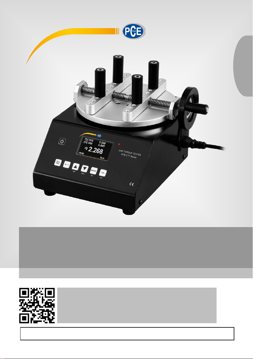
PCE-CTT Series Torque Meter
User Manual
User manuals in various languages (français,
italiano, español, português, nederlands, türk, polski,
русский, 中文) can be found by using our
product search on: www.pce-instruments.com
Last change: 15 February 2021
v1.1
English
Page 2

Contents
1 Safety notes ........................................................................................... 1
2 Specifications ........................................................................................ 2
3 Delivery scope ....................................................................................... 2
4 Device description ................................................................................ 2
4.1 Key description................................................................................................................. 3
4.2 Display description ........................................................................................................... 4
5 Measuring modes.................................................................................. 4
5.1 Real Time......................................................................................................................... 4
5.2 Peak................................................................................................................................. 4
5.3 Average Mode .................................................................................................................. 5
5.4 Save Mode ....................................................................................................................... 7
6 View / print saved data ......................................................................... 8
7 Alarm limits ............................................................................................ 9
8 Communication of interface and output interface ............................. 9
8.1 Data Software .................................................................................................................10
8.2 Graph Software ...............................................................................................................11
9 More settings ....................................................................................... 13
10 Contact ............................................................................................... 13
11 Disposal ............................................................................................... 13
© PCE Instruments
Page 3

© PCE Instruments
1
1 Safety notes
Please read this manual carefully and completely before you use the device for the first time. The
device may only be used by qualified personnel and repaired by PCE Instruments personnel.
Damage or injuries caused by non-observance of the manual are excluded from our liability and
not covered by our warranty.
• The device must only be used as described in this instruction manual. If used otherwise,
this can cause dangerous situations for the user and damage to the meter.
• The instrument may only be used if the environmental conditions (temperature, relative
humidity, …) are within the ranges stated in the technical specifications. Do not expose
the device to extreme temperatures, direct sunlight, extreme humidity or moisture.
• Do not expose the device to shocks or strong vibrations.
• The case should only be opened by qualified PCE Instruments personnel.
• Never use the instrument when your hands are wet.
• You must not make any technical changes to the device.
• The appliance should only be cleaned with a damp cloth. Use only pH-neutral cleaner,
no abrasives or solvents.
• The device must only be used with accessories from PCE Instruments or equivalent.
• Before each use, inspect the case for visible damage. If any damage is visible, do not
use the device.
• Do not use the instrument in explosive atmospheres.
• The measurement range as stated in the specifications must not be exceeded under
any circumstances.
• Non-observance of the safety notes can cause damage to the device and injuries to
the user.
• Gloves and a face shield must be worn during the test procedure to avoid injuries.
We do not assume liability for printing errors or any other mistakes in this manual.
We expressly point to our general guarantee terms which can be found in our general terms of
business.
If you have any questions please contact PCE Instruments. The contact details can be found at
the end of this manual.
Page 4
© PCE Instruments
2
2 Specifications
Model
Measurement range
Resolution
Accuracy
PCE-CTT 2
2 Nm
0.001 Nm
0.3 % of meas. range
PCE-CTT 5
5 Nm
0.002 Nm
PCE-CTT 10
10 Nm
0.005 Nm
Further specifications
Unit
Nm, kgFcm, lbFin
Direction of rotation
left and right
Clamping pins / sample holders
can be repositioned w/o tools / rubberised
Data memory
for up to 100 measured values
Display
LCD graphical display
Power supply
230 V
Sample size
20 ... 200 mm diameter
Sample weight
max. 5 kg
Environmental conditions
5 ... 45 °C, 35 ... 65 % RH
Dimensions
280 x 210 x 200 mm
Weight
approx. 9 kg
3 Delivery scope
1 x torque meter PCE-CTT series
1 x USB cable
1 x power cable
1 x software
1 x M6 hexagon key
1 x M5 hexagon key
4 x rubber feet
4 x rubberised sample holders
1 x user manual
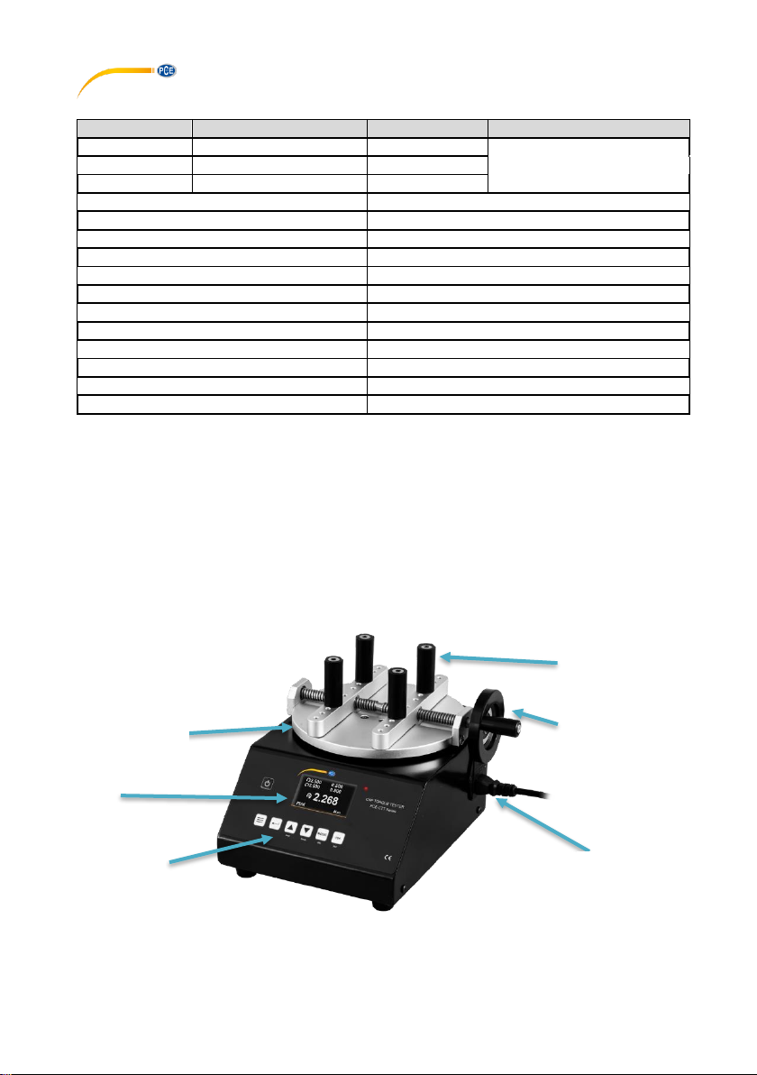
4 Device description
Display
Keyboard
Mains connection
Handwheel for
clamping the
samples
Rubber holders
Measuring plate
Page 5
© PCE Instruments
3
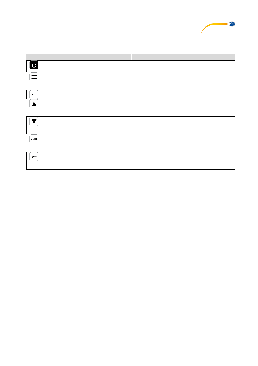
4.1 Key description
Key
Description
Function
Power key
Press and hold this key to turn the meter on
and off.
Menu key
Press this key to enter the menu. Press this
key repeatedly to select between the
individual menu pages or to exit the menu.
Enter key
Open parameters and apply settings.
Unit
Up key
(Unit key)
- Increase value
- Go up one parameter
- Select units
DATA
Down key
(Data key)
- Decrease value
- Go down one parameter
- Open memory
DEL
Mode key
(Del key)
- Select measuring mode
- Delete individual saved measured
values
ESC
Zero point key
(ESC key)
- Set zero point
- Apply setting
- Go one menu level back
Page 6
© PCE Instruments
4
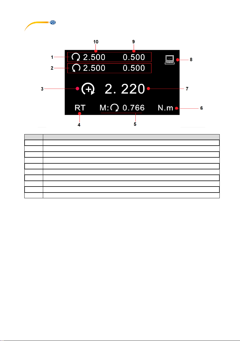
4.2 Display description
No.
Description
1
Limit value alarm for clockwise direction of rotation
2
Limit value alarm for counterclockwise direction of rotation
3
Measuring direction
4
Measuring mode
5
Last peak value in PEAK mode
6
Unit 7 Measured value
8
Connected to a PC
9
Set minimum limit value
10
Set maximum limit value
5 Measuring modes
This torque meter has four different measuring modes. If the measured value is outside the
measurement range, "OVER" is shown on the display and an acoustic signal is generated. Only
when the measured value is back within the measurement range, a normal measurement can be
resumed.
To switch between the modes, press the "MODE" key in the current measuring mode. The current
measuring mode is displayed below the measured value.
5.1 Real Time
In Real Time (RT) measuring mode, the current measured value is continuously displayed.
5.2 Peak
In peak mode (PK), the highest measured value is displayed and held. This measuring mode can
be used for tensile and compressive force. The peak value can be reset with the "Zero" key.
Page 7
© PCE Instruments
5
5.3 Average Mode
In Average (AVG) mode, the average value of a measurement is displayed. There are two
different functions in this measurement mode.
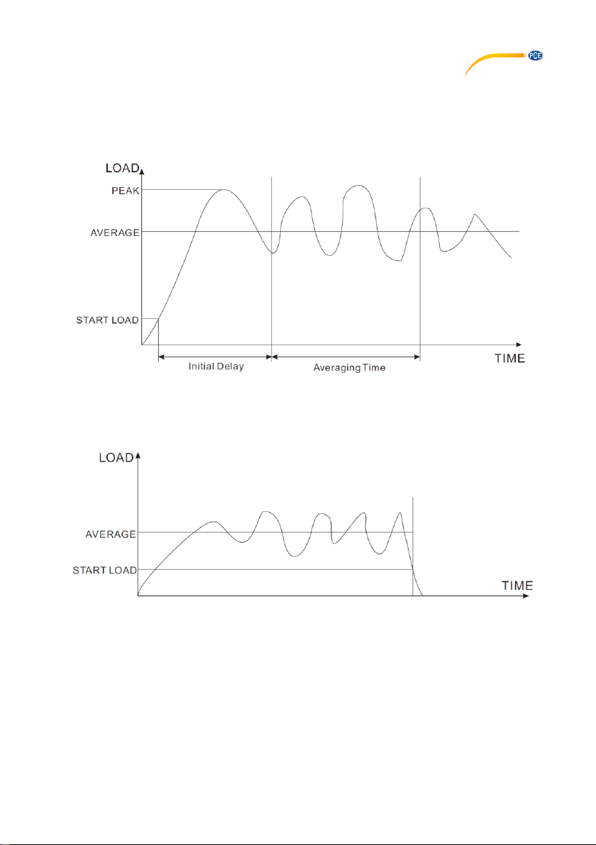
MOD1: With this function, the average value of the force curve is displayed starting from the set
minimum force and over the set period of time.
MOD2: This function calculates the average above the set minimum measured value. When the
measured value falls below the set minimum value again, the measurement is finished. This
measuring procedure is possible over a period of 10 minutes. As long as the measuring time of
10 minutes is not exceeded, this measurement can be resumed at any time.
Page 8
© PCE Instruments
6
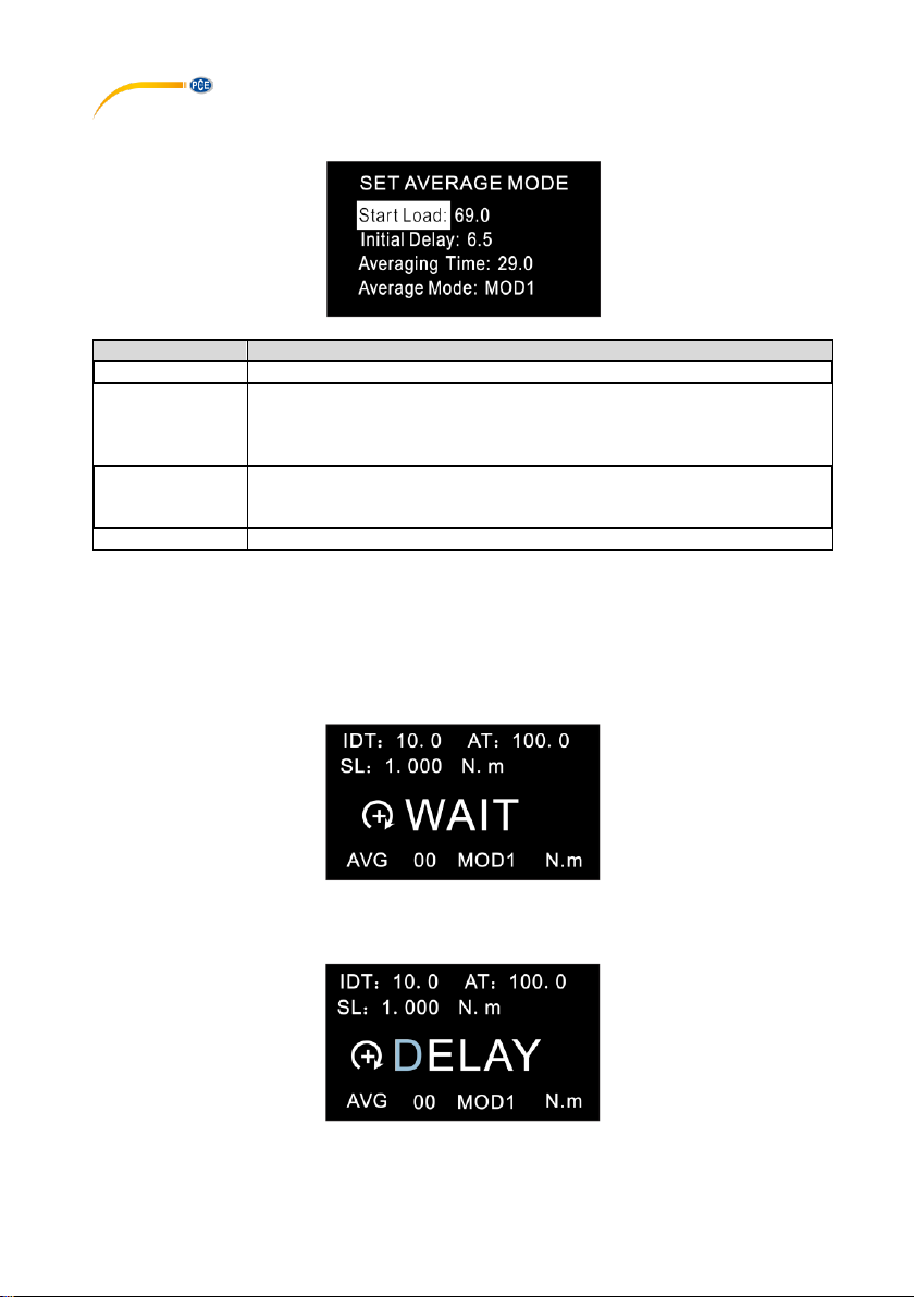
To make settings for this measuring mode, press the "Menu" key twice.
Setting
Meaning
Start Load
Here you set the force at which the average measurement should start.
Initial Delay
Here you enter the time span at the beginning of the measurement that is
not to be taken into account in the average measurement. Available
settings: 0.0 ... 300.0 seconds. Resolution 0.1 seconds. This parameter
only affects the MOD1 function.
Averaging Time
Here you set the measuring time for the average measurement. Available
settings: 0.0 ... 300.0 seconds. Resolution 0.1 seconds. This parameter
only affects the MOD1 function.
Average Mode
Here you select between the MOD1 and MOD2 function.
To select a parameter, use the arrow keys. Press the "Enter" key to select a parameter. Use the
arrow keys again to change the parameter properties. Press the "Enter" key again to apply the
settings you have made.
5.3.1 Measuring procedure
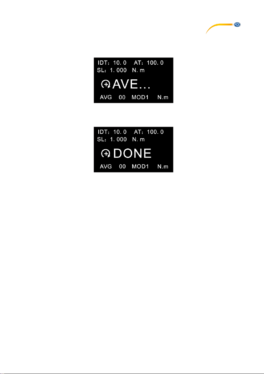
When "WAIT" is displayed on the screen, the meter waits until the set minimum load is applied.
When "DELAY" is shown on the display, the force gauge will wait until the set minimum time has
elapsed.
Page 9
© PCE Instruments
7
When the minimum load is present and the minimum time has elapsed, the actual measurement
begins. “AVE..." appears on the display. The measurement is made. During this measurement, it
is not possible to see the current measured value.
When the measurement is completed, the display shows "DONE". You will then see the average
reading.
To reset the average value to start a new measurement, press the "Zero" key. The measured
value is saved at the same time. Up to 10 average values can be saved.
5.4 Save Mode
In "SAVE Mode", the highest measured values can be saved in a single measurement run. In the
memory, you can save 100 measured values (memory item number 00 ... 99). The number of
memory items used is displayed to the left of "SAVE". As soon as a single measurement run is
completed, the highest measurement value is automatically saved. It is recommended to
permanently save the measurement data on an external PC as the measurement values saved
in the meter could be lost.
You can set the minimum load for this function in the settings under "Save Load". This can be
found on the third menu page "OTHER SETTINGS".
Page 10
© PCE Instruments
8
6 View / print saved data
To evaluate the saved data, press the "DATA" key. Then select "Save Mode Data" for the data
saved in "SAVE" mode or "Average Mode Data" to view the data saved in "AVE" mode.
Selection
Description
View Data
View all measurement data
View Statistics
The highest value, the lowest value and the average of all
saved values are displayed here.
Print Data
The saved measurement data is printed here.
Clear All Data
Deletes all measured values
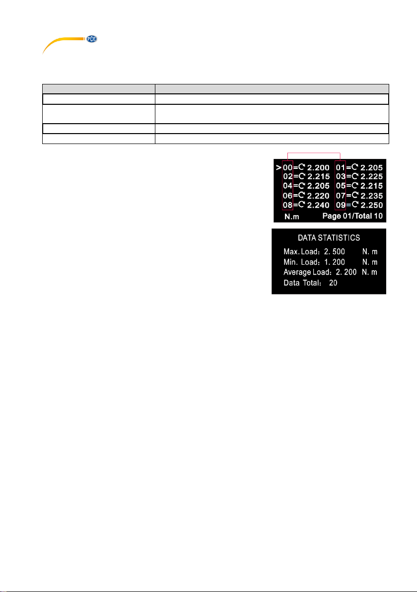
Under "View Data", the memory item number, the direction of
rotation and the measured value are displayed. You can now
select a measured value with the arrow keys. To switch
between the individual pages, press the "Menu" key. To delete
a single measured value, press and release the "DEL" key
once.
The highest value, the lowest value and the average of all
saved values are displayed here.
Page 11
© PCE Instruments
9
7 Alarm limits
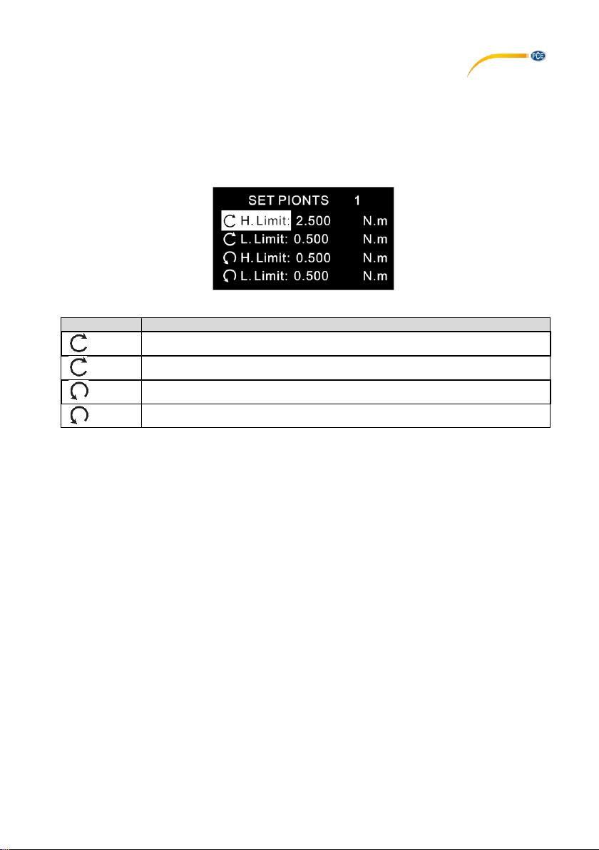
The alarm limits function is useful, for example, to check during quality control whether the tested
item is working within the specified tolerances. Two limits can be set here. If the measured value
is lower than the set "Lower Limit", this is indicated by the red and green LEDs lighting up. If the
measured value lies between the set "Higher Limit" and the set "Lower Limit", only the green LED
lights up. If the "Higher Limit" is also exceeded, only the red LED lights up.
Note: This function is only available in the measurement modes RT, PK and Save.
Display
Meaning
H. Limit
Highest limit value clockwise
L. Limit
Lowest limit value clockwise
H. Limit
Highest limit value counterclockwise
L. Limit
Lowest limit value counterclockwise
Now use the arrow keys to select the desired parameter. Press the "Enter" key to make
changes to this value. You can then change the value as desired with the arrow keys. Confirm
the entry with the "Enter" key. Press the "ESC" key to return to measuring mode.
Note: The second limit value must always be higher than the first set limit value. The set values
are shown above the reading in measuring mode.
8 Communication of interface and output interface
There are two different softwares for the torque meter. Both do not need to be installed. If the
computer does not find the correct drivers, you will find them in the installation folder.
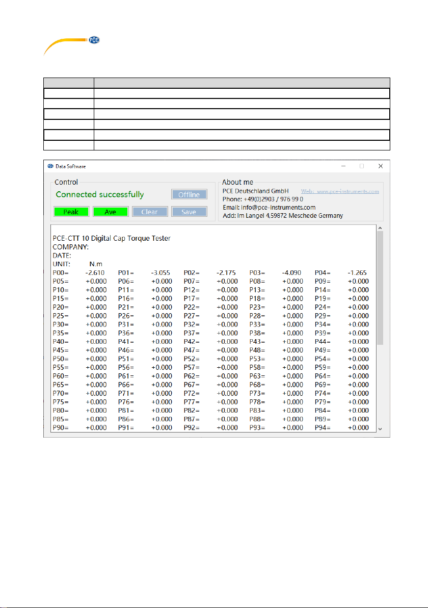
With the Data Software, the memory can be read out and processed. With the Graph Software,
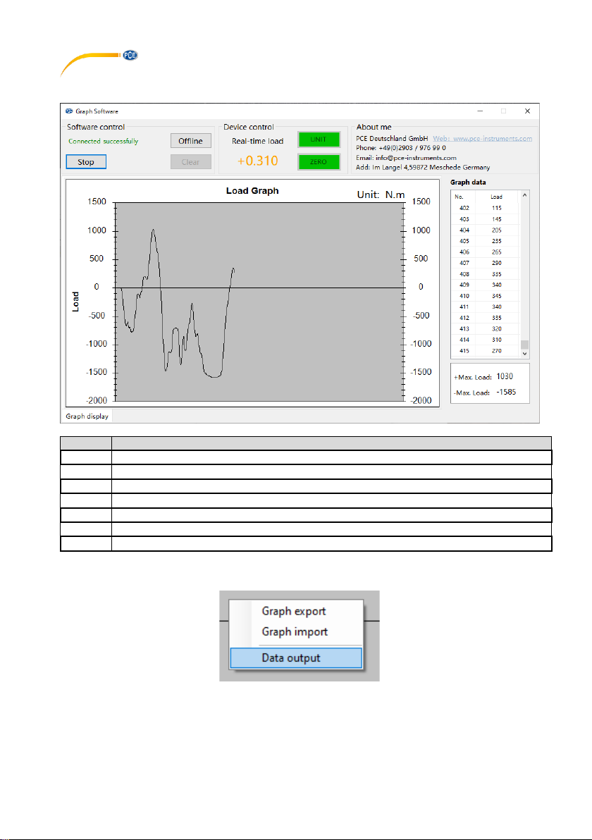
the current measured values can be transferred live to a PC and transmitted both graphically and
in tabular form.
Page 12
© PCE Instruments
10
8.1 Data Software
With the Data Software, the saved data can be transferred directly to a PC.
Button
Function
Offline
Click this button to disconnect from the meter.
Online
Click this button to connect to the meter.
Peak
Transfers all saved data that have been saved in the "SAVE" mode
Ave
Transfers all saved data that have been saved in "AVE" mode
Clear
Clears the text field (does not clear the memory)
Save
Saves the text field in TXT format
Page 13
© PCE Instruments
11
8.2 Graph Software
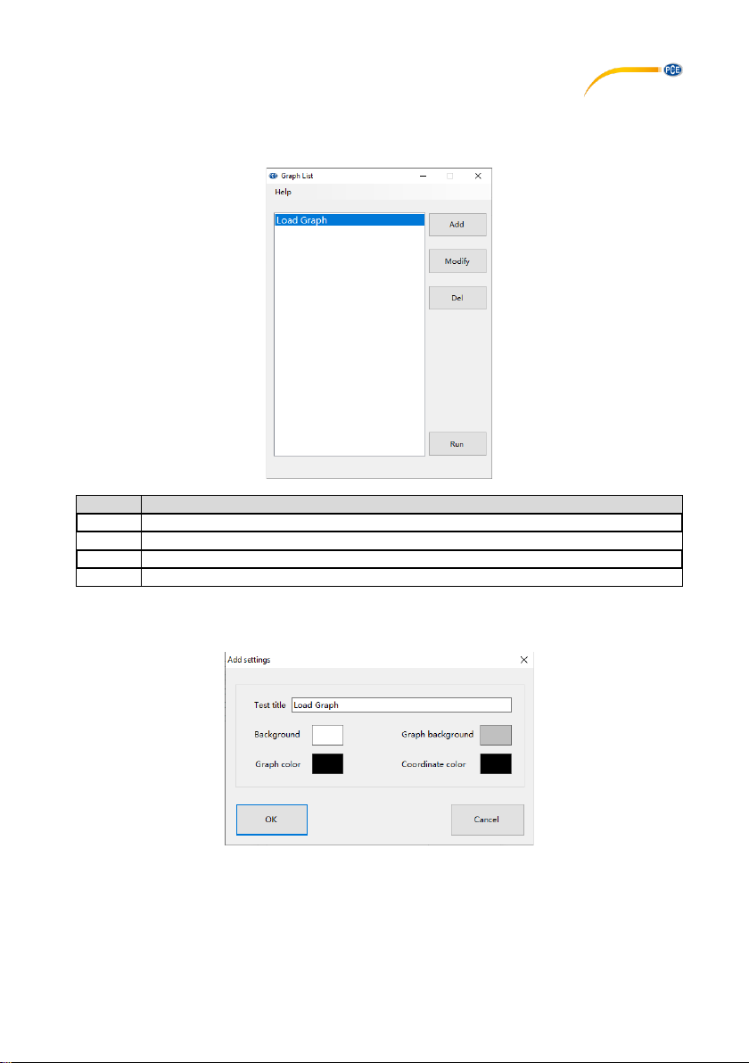
The Graph Software enables a live display of all data on the PC. When you open the
programme, you first see a list of graphs in the colours you have set.
Button
Function
Add
Add a layout
Modify
Change a layout
Del
Delete a layout
Run
Starts the layout
When you create or edit a layout, the following window appears. Here you can change the
name and set the colours as required.
Page 14
© PCE Instruments
12
After you have selected your layout, the following window opens:
Button
Function
Start
Starts the recording in the software
Stop
Stops the recording in the software
Offline
Disconnects from the meter
Online
Establishes a connection to the meter
Clear
Deletes all displayed values
UNIT
Switches the unit
Zero
Resets the zero point
To save the displayed data, right-click on the graph.
Here you can export the graph and also import it again. The data can also be exported in TXT
format via "Data output".
Important: The exported graph can only be displayed again via the software.
Page 15
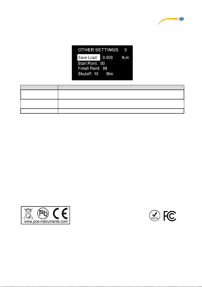
9 More settings
Function
Description
Save Load
Here you can set the minimum value that must be reached so that the
measured value is saved.
Start Finish Point
Here you can set which memory item is to be used for saving or
printing, for example.
Shutoff
Here you can set the time for automatic power-off.
You can access further settings for the meter by pressing the "Menu" key three times. This will
take you to the "Other Settings" menu page.
10 Contact
If you have any questions, suggestions or technical problems, please do not hesitate to contact
us. You will find the relevant contact information at the end of this user manual.
11 Disposal
For the disposal of batteries in the EU, the 2006/66/EC directive of the European
Parliament applies. Due to the contained pollutants, batteries must not be disposed of as
household waste. They must be given to collection points designed for that purpose.
In order to comply with the EU directive 2012/19/EU we take our devices back. We either reuse them or give them to a recycling company which disposes of the devices in line with law.
For countries outside the EU, batteries and devices should be disposed of in accordance
with your local waste regulations.
If you have any questions, please contact PCE Instruments.
© PCE Instruments
13
Page 16

© PCE Instruments
14
PCE Instruments contact information
Germany France Spain
PCE Deutschland GmbH PCE Instruments France EURL PCE Ibérica S.L.
Im Langel 4 23, rue de Strasbourg Calle Mayor, 53
D-59872 Meschede 67250 Soultz-Sous-Forets 02500 Tobarra (Albacete)
Deutschland France España
Tel.: +49 (0) 2903 976 99 0 Téléphone: +33 (0) 972 3537 17 Tel. : +34 967 543 548
Fax: +49 (0) 2903 976 99 29 Numéro de fax: +33 (0) 972 3537 18 Fax: +34 967 543 542
[email protected] [email protected] [email protected]
www.pce-instruments.com/deutsch www.pce-instruments.com/french www.pce-instruments.com/espanol
United Kingdom Italy Turkey
PCE Instruments UK Ltd PCE Italia s.r.l. PCE Teknik Cihazları Ltd.Şti.
Unit 11 Southpoint Business Park Via Pesciatina 878 / B-Interno 6 Halkalı Merkez Mah.
Ensign Way, Southampton 55010 Loc. Gragnano Pehlivan Sok. No.6/C
Hampshire Capannori (Lucca) 34303 Küçükçekmece - İstanbul
United Kingdom, SO31 4RF Italia Türkiye
Tel: +44 (0) 2380 98703 0 Telefono: +39 0583 975 114 Tel: 0212 471 11 47
Fax: +44 (0) 2380 98703 9 Fax: +39 0583 974 824 Faks: 0212 705 53 93
[email protected] [email protected] [email protected]
www.pce-instruments.com/english www.pce-instruments.com/italiano www.pce-instruments.com/turkish
The Netherlands China Hong Kong
PCE Brookhuis B.V. PCE (Beijing) Technology Co., Limited PCE Instruments HK Ltd.
Institutenweg 15 1519 Room, 6 Building Unit J, 21/F., COS Centre
7521 PH Enschede Zhong Ang Times Plaza 56 Tsun Yip Street
Nederland No. 9 Mentougou Road, Tou Gou District Kwun Tong
Telefoon: +31 (0)53 737 01 92 102300 Beijing, China Kowloon, Hong Kong
[email protected] Tel: +86 (10) 8893 9660 Tel: +852-301-84912
www.pce-instruments.com/dutch [email protected] [email protected]
www.pce-instruments.cn www.pce-instruments.cn
United States of America
PCE Americas Inc.
1201 Jupiter Park Drive, Suite 8
Jupiter / Palm Beach
33458 FL
USA
Tel: +1 (561) 320-9162
Fax: +1 (561) 320-9176
[email protected]
www.pce-instruments.com/us
 Loading...