

Page 1

© PCE Instruments
PCE-CTI 10 Clamp Meter
User Manual
User manuals in various languages (français,
italiano, español, português, nederlands, türk, polski,
русский, 中文) can be found by using our
product search on: www.pce-instruments.com
Last change: 27 May 2024
v1.0
English
Page 2

© PCE Instruments
Contents
1 Safety notes ...................................................................................................... 1
2 Specifications ................................................................................................... 2
3 Delivery scope .................................................................................................. 4
4 Device description ........................................................................................... 5
4.1 Key description .......................................................................................................................................... 6
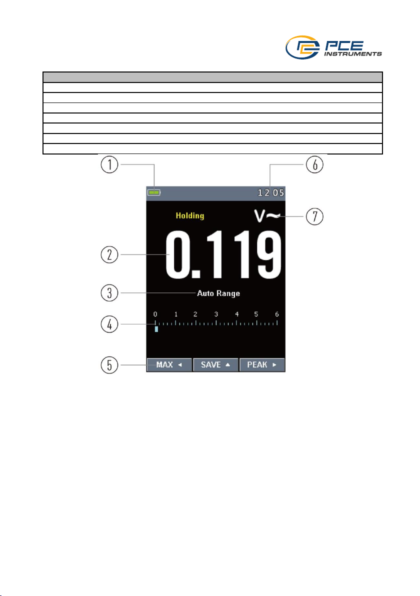
4.2 Display description ..................................................................................................................................... 7
4.3 Rotary selector switch ................................................................................................................................ 9
5 Making a measurement .................................................................................. 10
5.1 Voltage measurement .............................................................................................................................. 10
5.2 Frequency measurement and duty cycle measurement ......................................................................... 10
5.3 Resistance, capacitance measurement, diode test and continuity test .................................................. 11
5.4 Temperature measurement ..................................................................................................................... 11
5.5 Current measurement .............................................................................................................................. 12
5.6 Inrush current measurement ................................................................................................................... 12
5.7 Current measurement with external current clamp ................................................................................. 13
5.8 Frequency inverter ................................................................................................................................... 13
5.9 Freeze measured value ........................................................................................................................... 13
5.10 Highest and lowest measured value........................................................................................................ 14
5.11 Set measured value in relation ................................................................................................................ 14
5.12 Peak values ............................................................................................................................................. 14
5.13 Non-contact voltage verification (NCV) ................................................................................................... 15
6 Menu ................................................................................................................ 15
6.1 Data logger .............................................................................................................................................. 16
6.2 Set language ............................................................................................................................................ 18
6.3 Settings .................................................................................................................................................... 18
6.4 Set system time and date ........................................................................................................................ 19
6.5 Device information ................................................................................................................................... 19
6.6 Call up screenshots ................................................................................................................................. 19
6.7 Restore factory settings ........................................................................................................................... 20
7 Bluetooth connection .................................................................................... 20
8 Contact ............................................................................................................ 21
9 Disposal .......................................................................................................... 21
Page 3

© PCE Instruments
1
1 Safety notes
Please read this manual carefully and completely before you use the device for the first time. The
device may only be used by qualified personnel and repaired by PCE Instruments personnel.
Damage or injuries caused by non-observance of the manual are excluded from our liability and
not covered by our warranty.
• The device must only be used as described in this instruction manual. If used otherwise,
this can cause dangerous situations for the user and damage to the meter.
• The instrument may only be used if the environmental conditions (temperature, relative
humidity, …) are within the ranges stated in the technical specifications. Do not expose
the device to extreme temperatures, direct sunlight, extreme humidity or moisture.
• Do not expose the device to shocks or strong vibrations.
• The case should only be opened by qualified PCE Instruments personnel.
• Never use the instrument when your hands are wet.
• You must not make any technical changes to the device.
• The appliance should only be cleaned with a damp cloth. Use only pH-neutral cleaner,
no abrasives or solvents.
• The device must only be used with accessories from PCE Instruments or equivalent.
• Before each use, inspect the case for visible damage. If any damage is visible, do not
use the device.
• Do not use the instrument in explosive atmospheres.
• The measurement range as stated in the specifications must not be exceeded under
any circumstances.
• Non-observance of the safety notes can cause damage to the device and injuries to
the user.
We do not assume liability for printing errors or any other mistakes in this manual.
We expressly point to our general guarantee terms which can be found in our general terms of
business.
Page 4
© PCE Instruments
2
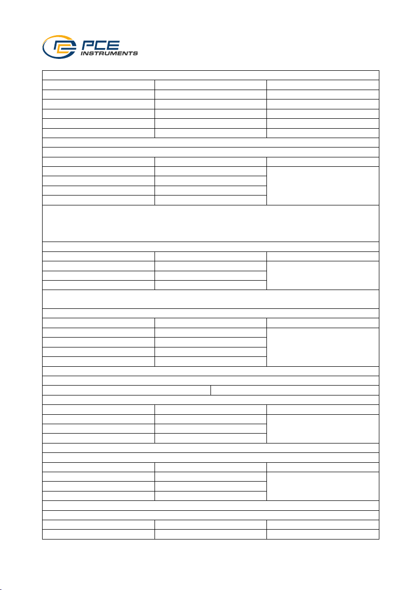
2 Specifications
DC voltage
Measurement range
Resolution
Accuracy
±600.0 mV
0.1 mV
±(0.8% + 8 digits) of Rd
±6.000 V
0.001 V
±(0.5% + 5 digits) of Rd
±60.00 V
0.01 V
±(0.5% + 5 digits) of Rd
± 600.0 V
0.1 V
±(0.8% + 5 digits) of Rd
±1500 V
1 V
±(0.8% + 5 digits) of Rd
Input impedance: >10 MΩ; overvoltage protection: 1500 VDC / 1000 VAC rms
Alternating voltage
Measurement range
Resolution
Accuracy
0.000 ... 6.000 V
0.001 V
50 ... 60 Hz: ±(1.2 % + 5
digits) of Rd
61 ... 1 kHz: ±(2.5 % + 5
digits) of Rd
0.00 ... 60.00 V
0.01 V
0.0 ... 600.0 V
0.1 V
0 ... 1500 V
1 V
The accuracy refers to 10 ... 100 % of the respective measurement range and one sine wave
Input impedance: >9 MΩ; overvoltage protection: 1000 V DC/AC RMS
The accuracy of the "PEAK" function is: ±10 % of Rd
The response time of the "PEAK" function is: 1 ms
AC voltage with low input impedance (LowZ)
Measurement range
Resolution
Accuracy
0.000 ... 6.000 V
0.001 V
±(3.0 % + 40 digits) v. Rd
0.00 ... 60.00 V
0.01 V
0.0 ... 300.0 V
0.1 V
Input impedance: 300 kΩ; overvoltage protection: 1000 VDC / VAC RMS
The accuracy refers to 10 ... 100 % of the respective measurement range and one sine wave
DC and AC voltage (50 ... 1 kHz)
Measurement range
Resolution
Accuracy
0.000 ... 6.000 V
0.001 V
±(2.5 % of Rd + 40 digits)
0.00 ... 60.00 V
0.01 V
0.0 ... 600.0 V
0.1 V
0 ... 1000 V
1 V
Input impedance: 300 kΩ; overvoltage protection: 1000 VDC / VAC RMS
Non-contact voltage verification (NCV)
Detection range
100 ... 1000 AC/DC
DC and AC voltage with low input impedance (LowZ)
Measurement range
Resolution
Accuracy
0.000 ... 6.000 V
0.001 V
±(3.5 % of Rd + 40 digits)
0.00 ... 60.00 V
0.01 V
0.0 ... 300.0 V
0.1 V
Input impedance: 300 kΩ; overvoltage protection: 1000 VDC / VAC RMS
Direct current
Measurement range
Resolution
Accuracy
±60.00 A
0.01 A
±(3.0 % of Rd + 8 digits)
±600.0 A
0.1 A
±1000 A
1 A
Overload protection: 1000 A AC/DC
Alternating current (50 ... 60 Hz)
Measurement range
Resolution
Accuracy
0.00 ... 60.00 A
0.01 A
±(2.5 % of Rd + 5 digits)
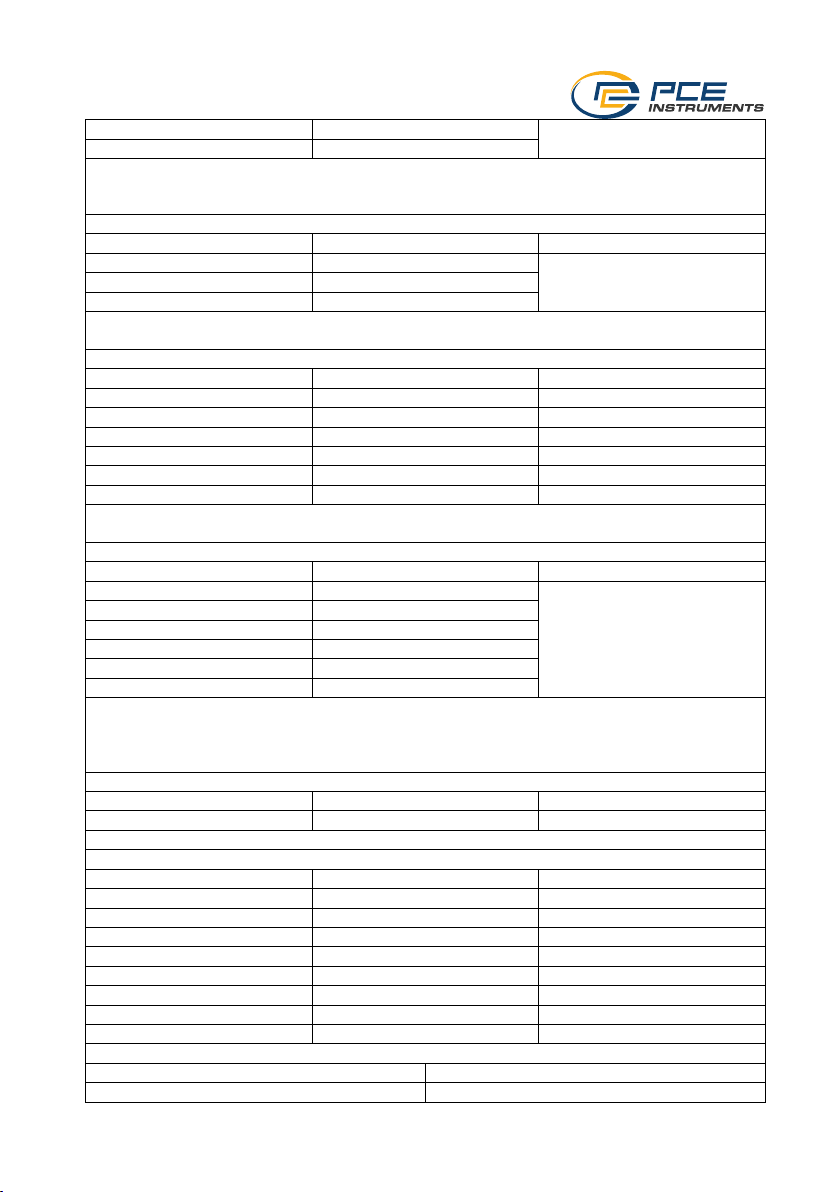
Page 5
© PCE Instruments
3
0.0 ... 600.0 A
0.1 A
0 ... 1000 A
1 A
Overload protection: 1000 A AC/DC
The accuracy refers to 10 ... 100 % of the respective measurement range and one sine wave
The inrush current measurement serves only as a reference
AC current measurement with flexible current clamp (50 ... 400 Hz)
Measurement range
Resolution
Accuracy
0.00 ... 30.00 A
0.01 A
±(3.0 % of of Rd + 5 digits)
0.0 ... 300.0 A
0.1 A
0 ... 3000 A
1 A
Overload protection: 1000 A AC/DC
The accuracy refers to 10 ... 100 % of the respective measurement range and one sine wave
Resistance and continuity measurement
Measurement range
Resolution
Accuracy
0.0 ... 600.0 Ω
0.1 Ω
±(1.0 % of Rd + 10 digits)
0.000 ... 6.000 kΩ
0.001 kΩ
±(0.8 % of Rd + 5 digits)
0.00 ... 60.00 kΩ
0.01 kΩ
±(0.8 % of Rd + 5 digits)
0.0 ... 600.0 kΩ
0.1 kΩ
±(0.8 % of Rd + 5 digits)
0.000 ... 6.000 MΩ
0.001 MΩ
±(0.8 % of Rd + 5 digits)
0.00 ... 60.00 MΩ
0.01 MΩ
±(2.5 % of Rd + 10 digits)
Continuity test signal tone at: <50 Ω
Overvoltage protection: 1000 V AC/DC
Frequency measurement
Measurement range
Resolution
Accuracy
0.00 ... 60.00 Hz
0.01 Hz
±(0.2 % of Rd + 5 digits)
0.0 ... 600.0 Hz
0.1 Hz
0.000 ... 6.000 kHz
0.001 kHz
0.00 ... 60.00 kHz
0.01 kHz
0.0 ... 600.0 kHz
0.1 kHz
0.000 ... 6.000 MHz
0.001 MHz
Overvoltage protection: 1000 V AC/DC
Sensitivity:
>2 Vrms with a duty cycle between 20 ... 80 % and a frequency of <100 kHz
>5 Vrms with a duty cycle between 20 ... 80 % and a frequency of >100 kHz
Duty cycle
Measurement range
Resolution
Accuracy
10.0 ... 90.0 %
0.1 %
±(1.2 % of Rd + 8 digits)
Frequency range: 40 ... 10 kHz; pulse amplitude ±5 V with a duration of 100 µs ... 100 mS
Capacity
Measurement range
Resolution
Accuracy
0.00 ... 60.00 nF
0.01 nF
±(3.0 % of Rd + 20 digits)
0.0 ... 600.0 nF
0.1 nF
±(3.0 % of Rd + 8 digits)
0.000 ... 6,000 µF
0.001 µF
±(3.0 % of Rd + 8 digits)
0.00 ... 60.00 µF
0.01 µF
±(3.0 % of Rd + 8 digits)
0.0 ... 600.0 nF
0.1 nF
±(3.0 % of Rd + 8 digits)
0 ... 6000 µF
1 µF
±(3.5 % of Rd + 20 digits)
0.00 ... 60.00 mF
0.01 mF
for reference only
0.0 ... 600.0 mF
0.1 mF
for reference only
Diode test
Test current
<1.5 mA
Maximum voltage
3.3 VDC
Page 6

© PCE Instruments
4
Further specifications
Memory space
16 groups with a total memory capacity of
100,000 measured values
Clamp diameter horizontal
38 mm / 1.49"
Clamp diameter vertical
63 mm / 2.48"
Clamp aperture
45 mm / 1.77"
Protection class
IP65
Interface
Bluetooth 4.0
Degree of pollution
2
Insulation categories
CAT IV 600 V, CAT III 1000 V, CAT II 1500 V
Maximum working height
2000 m / 6562 ft
Power supply battery
7.4 V, 1200 mAh Li-ion battery
Power supply charger
Primary: 100 ... 240 V AC, 50 ... 60 Hz
Secondary: 12 V DC, 2 A
Charger plug connection
Europe, USA, England, China
Battery status display
available
Automatic power-off
off, 15, 30 or 60 minutes
Display
2.36 " TFT
Display frequency
3 Hz
Reference conditions
18 ... 28 °C, 64 ... 82 °F; <80 % RH,
non-condensing
Operating conditions
5 ... 40 °C, 41 ... 104 °F; <80 % RH,
non-condensing
Storage conditions
-20 ... 60 °C, -4 ... 140 °F; <80 % RH,
non-condensing
Dimensions
275 x 100 x 45 mm / 10.8 x 3.9 x 1.7"
Weight
481 g / 16.9 oz
3 Delivery scope
1 x clamp meter PCE-CTI 10
1 x K-type thermocouple with adaptor
1 x pair of test leads
1 x carrying case
1 x battery charging station
1 x rechargeable battery
1 x user manual
Page 7
© PCE Instruments
5
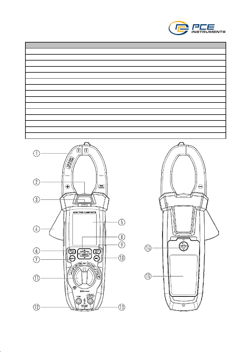
4 Device description
No.
Description
1
Current clamp
2
Torch
3
NCV indicator. As soon as this lamp lights up, a voltage has been detected.
4
Lever for opening the current clamp
5
Display
6
"MODE / VFD" key
7
"RANGE" key
8
"INRUSH / Menu" key
9
"HOLD / REL" key
10
Light key
11
Rotary selector switch
12
Connection for test leads (-)
13
Connection for test leads (+)
14
Lock of the battery cover
15
Battery cover
Page 8
© PCE Instruments
6
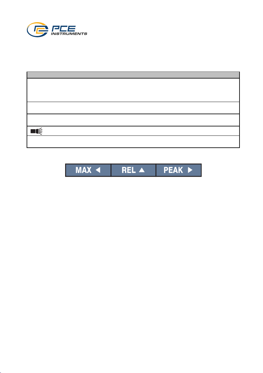
4.1 Key description
The meter has 9 keys which can change their function depending on the set position of the rotary
selector switch.
4.1.1 Real keys
Button
Description
HOLD / REL
- Freezes the display in order to
subsequently save the displayed
measured value
- Sets the measured value in relation
MODE / VFD
- Switching between the individual
functions
RANGE
- Manual switching of the measurement
range
- Switching the torch on and off
INRUSH / Menu
- Starting inrush current measurement
- Open menu
4.1.2 Virtual keys
The virtual keys are shown on the display. These are actuated by the real arrow keys. The virtual
keys change their functions depending on the setting.
Page 9
© PCE Instruments
7
4.2 Display description
No.
Description
1
Battery status display
2
Measured value
3
Automatic or manual selection of the measurement range
4
Bar chart in relation to the set measurement range
5
Virtual key
6
System time
7
Unit of meaurement
Page 10
© PCE Instruments
8
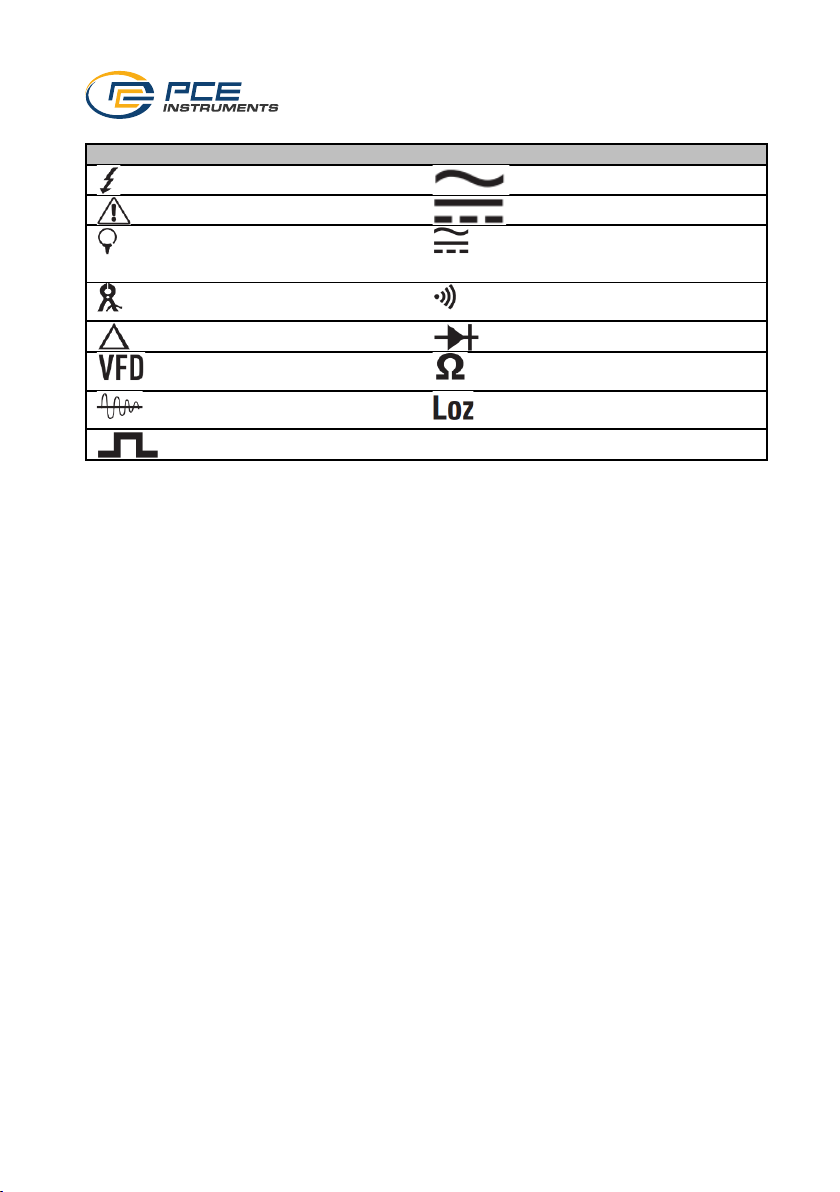
4.2.1 Display symbols
Symbols
Function
Symbols
Function
Voltage above 30 V AC or DC
Alternating voltage or current
Warning
Direct voltage or current
Measurement via the current
clamp
Alternating voltage or current
with direct voltage or direct
current component
Measurement via the existing
current clamp
Continuity test
Measured value in relation
Diode test
Function: measurement on a
frequency inverter
Unit symbol for ohm
Function: inrush current
measurement
Measurement with low
impedance
Time of the high edge
Page 11
© PCE Instruments
9
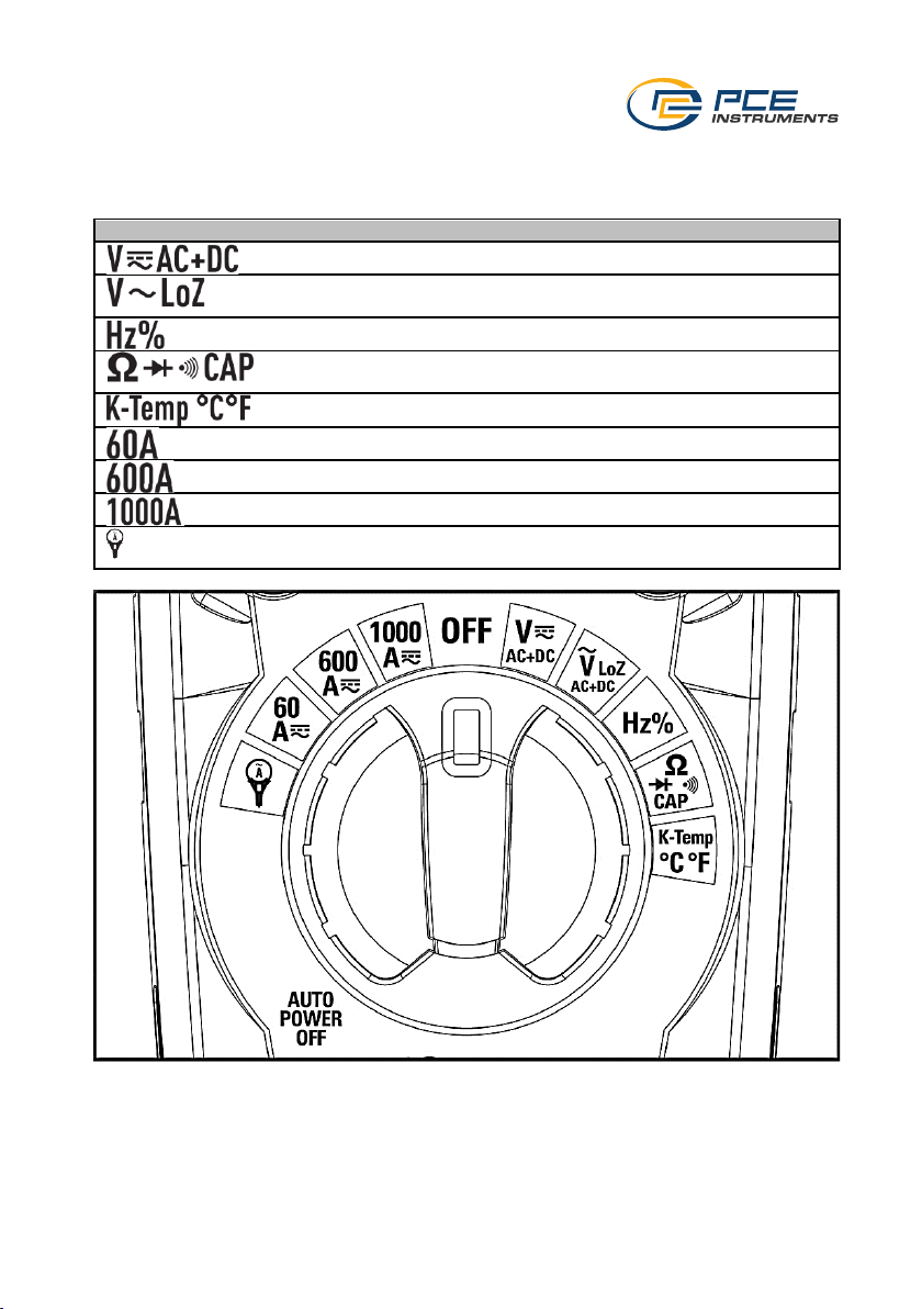
4.3 Rotary selector switch
To operate the meter, select the desired function using the rotary selector switch. The meter will
switch on immediately. To switch off the meter, set the rotary selector switch to "OFF".
Function
Description
Direct and / or alternating voltage measurement
Direct and / or alternating voltage measurement with low input
resistance
Frequency measurement and duty cycle measurement
Resistance measurement, diode test, continuity measurement,
capacitance measurement
Temperature measurement
Alternating or direct current measurement up to 60 A
Alternating or direct current measurement up to 600 A
Alternating or direct current measurement up to 1000 A
Alternating current measurement with external current clamp up to
3000 A
Page 12
© PCE Instruments
10
5 Making a measurement
To carry out a measurement, the meter must be set appropriately for the measurement task
before the test leads are connected. Voltage and current peaks can damage the meter. Ensure
that the contacts are correctly connected for each measurement. Failure to do so may result in
incorrect measurements.
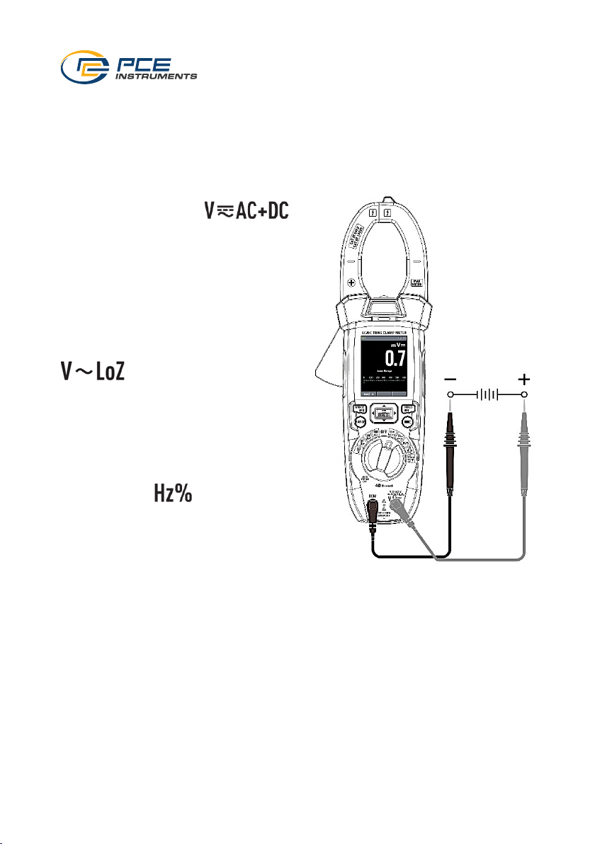
5.1 Voltage measurement
To carry out a voltage measurement, first set
the rotary selector switch to .
Now connect the test leads to the device. Use
the "MODE VFD" key to switch between the
direct voltage, alternating voltage, direct and
alternating voltage and frequency
measurement functions.
5.1.1 Measurements with low
impedance
To make a voltage measurement with a low
impedance, turn the rotary selector switch to
. The "MODE VFD" key can be
used to select between the direct voltage,
alternating voltage and direct and alternating
voltage functions.
5.2 Frequency measurement and duty
cycle measurement
For a frequency measurement, turn the rotary
selector switch to . The "MODE VFD"
key can now be used to select between
frequency measurement and duty cycle.
Page 13
© PCE Instruments
11
5.3 Resistance, capacitance measurement, diode test and continuity test
To make a resistance or capacitance measurement, a diode test or continuity test, set the rotary
selector switch to . The "MODE VFD" key can be used to select between the
individual functions.
Note: Make sure that capacitors are discharged before a capacitance measurement. They could
be fully charged after a measurement. They must be discharged after a measurement as there is
a risk of electric shock.
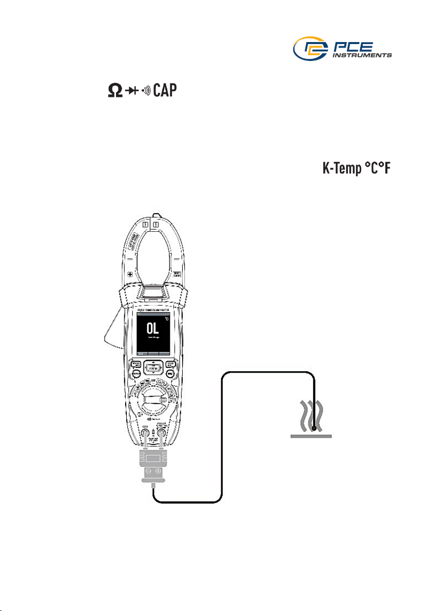
5.4 Temperature measurement
To carry out a temperature measurement, set the rotary selector switch to .
Connect the temperature adaptor for thermocouples to the device. Then connect a suitable
thermocouple to the adaptor. The measurement is carried out immediately. Use the "MODE VFD"
key to select between °C and °F.
Page 14
© PCE Instruments
12
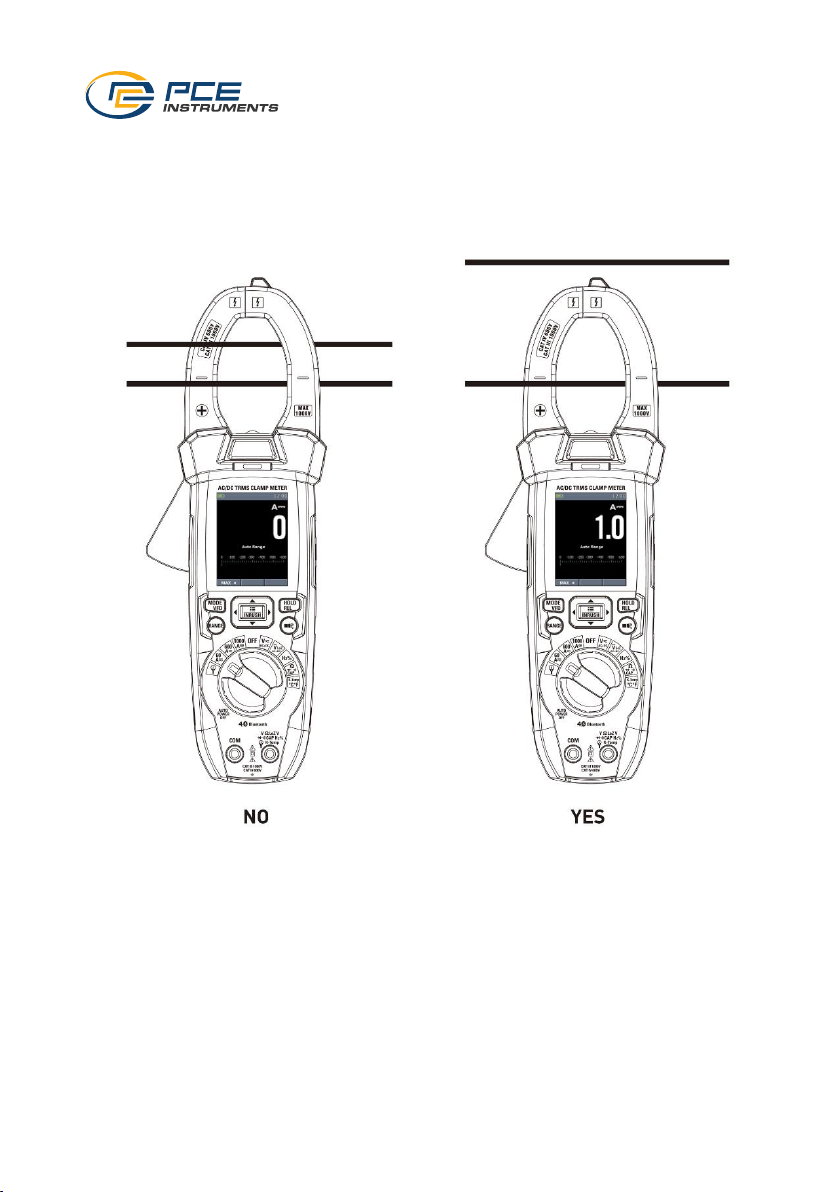
5.5 Current measurement
To carry out a current measurement with the current clamp, set the rotary selector switch to one
of the current measurement end values. A maximum of 60, 600 and 1000 A are available. The
"MODE" key can be used to select between direct and alternating current. Use the "REL" key to
set the current in relation to another current. Then place the current clamp around the supply
cable to be measured. Make sure that there is only one cable in the clamp.
5.6 Inrush current measurement
The inrush current measurement is only possible when measuring the current with the fixed
current clamp and with an alternating current. To carry out this measurement, press and hold the
"INRUSH/Menu" key for at least two seconds. You can then switch on the device under test. The
measurement starts immediately and the inrush current is shown on the display.
Page 15
© PCE Instruments
13
5.7 Current measurement with external current clamp
To carry out a measurement with an external current clamp, set the rotary selector switch to .
Then connect the external current clamp to the device and compare the set measurement range
to the setting on the current clamp. To set the measurement range of the device, press the
"Range" key repeatedly.
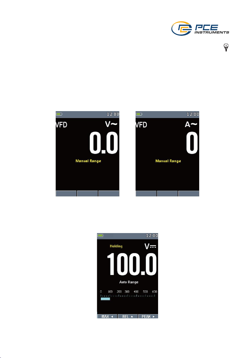
5.8 Frequency inverter
To carry out measurements on a frequency inverter, the function must first be activated by
pressing and holding the "VFD" key. You can then carry out measurements on a frequency
converter. This function is available for alternating current and voltage.
To exit this mode, press and hold the key again.
5.9 Freeze measured value
To freeze the measured value, briefly press the "HOLD/REL" key once. Press the key again to
resume normal measurement. If the value is frozen, the displayed image can be saved using the
virtual "Save" key. The screenshots can be recalled and deleted in the "Memory" menu item.
Page 16
© PCE Instruments
14
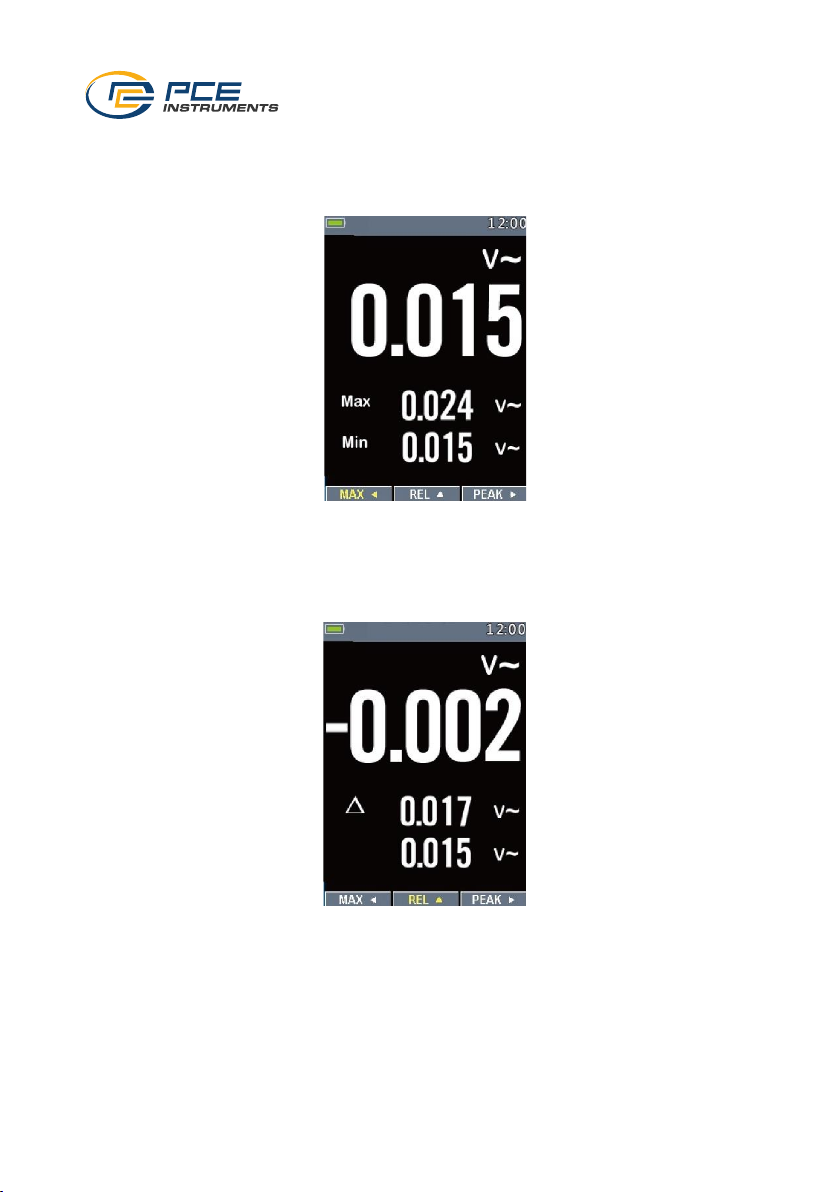
5.10 Highest and lowest measured value
To display the highest and lowest measured values, press the virtual "MAX" key. The highest and
lowest measured values are now shown on the display next to the current measured value. To
return to the normal view, press the key again.
5.11 Set measured value in relation
To display the measured value in relation, press and hold the "HOLD / REL" key. The current
measured value, the measured value set in relation and the base measured value are now shown
on the display. To return to the normal view, press the key again.
5.12 Peak values
To display the peak value, press the virtual "PEAK" key. The highest and lowest peak values are
displayed next to the normal measurement. To reset the display, exit the mode and open it again.
Page 17
© PCE Instruments
15
5.13 Non-contact voltage verification (NCV)
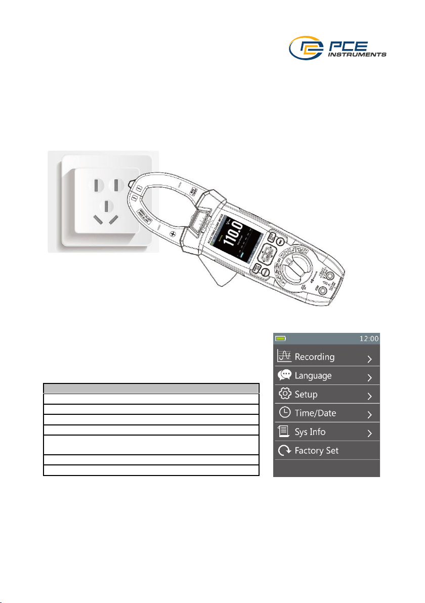
To carry out a non-contact voltage check, the device only needs to be switched on. This function
is always active. For the test, the tip of the current clamp must be held against the cable, fuse,
socket, etc. to be tested. The control LED then signals the presence of a voltage between 100 ...
1000 V.
Note: Insulation, shielding and distances influence the display. Before a measurement, this
function should be checked with a known voltage, for example on a supply line. The meter has a
sensitive sensor system. External voltage can cause the control LED to light up.
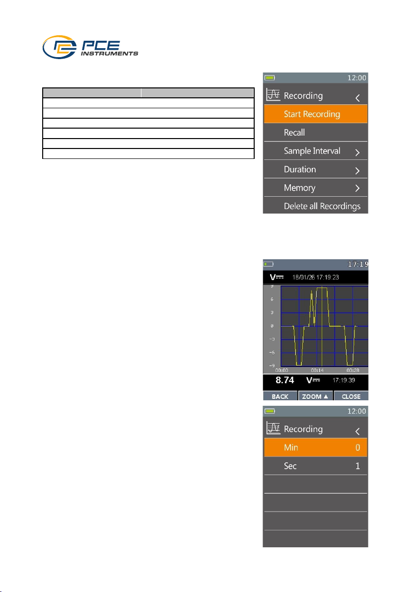
6 Menu
To open the menu to make settings, press the menu key. The
arrow keys can be used to select between the individual
functions and parameters can be changed. Use the menu key
and the right arrow key to open the menu level and apply
settings. Press the left arrow key to go back one level.
Menu
Function
Recording
Data recording
Language
Set language
Setup
Further settings
Time/Date
Date and time
Memory
Retrieving screenshots of the "Hold"
function
Information
Device information
Factory Set
Reset meter
Page 18
© PCE Instruments
16
6.1 Data logger
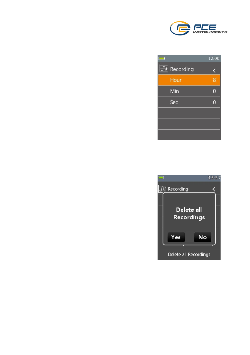
To start the data logger, go to the "Recording" menu.
6.1.1 Start data recording
To start data recording, select "Start Recording" in the "Recording" menu. Recording starts
immediately. The appropriate settings for recording should be made in advance.
6.1.2 Retrieve recorded data
To retrieve the saved data, go to "Recall" in the "Recording"
menu. The last value is displayed there. Press "Close" to
return to the menu. Via "Trend", you can see a graphical
history of the last recordings. Use the arrow keys to move to
each individual point. Zoom can be used to zoom closer into
the graph. If you press the zoom key repeatedly, you will
return to the overall view.
6.1.3 Set storage interval
To set the storage interval, go to "Sample Interval" in the
"Recording" menu item. Here, you can set the storage
interval in minutes and seconds.
Menu
Function
Start Recording
Recording is started
Recall
Retrieve measured values
Sample Interval
Setting the memory interval
Duration
Storage duration
Memory
Display of the memory space
Delete all Recordings
Delete all measurement data
Page 19
© PCE Instruments
17
6.1.4 Setting the data logger duration
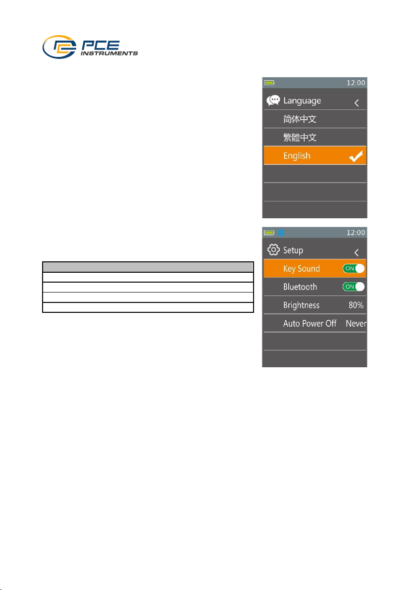
To set the data logger duration, go to "Duration" in the
"Recording" menu item. Here, you can specifically set the
duration of the recording.
6.1.5 View memory space
To find out how much memory space is still available, go to "Memory" in the "Recording" menu
item. There you can see how much memory space is already in use.
6.1.6 Clear memory
To clear the entire memory, select "Delete all Recordings" in
the "Recording" menu item. You will be asked whether you
really want to clear the memory. Confirm this if you do.
Page 20
© PCE Instruments
18
6.2 Set language
To set the language, go to the "Language" menu. Here you
can choose between the specified system languages.
6.3 Settings
To make settings, go to the "Setup" menu.
Menu
Function
Key Sound
Key sound
Bluetooth
Switching Bluetooth on and off
Brightness
Setting the display brightness
Auto Power Off
Setting the automatic power-off time
Page 21
© PCE Instruments
19
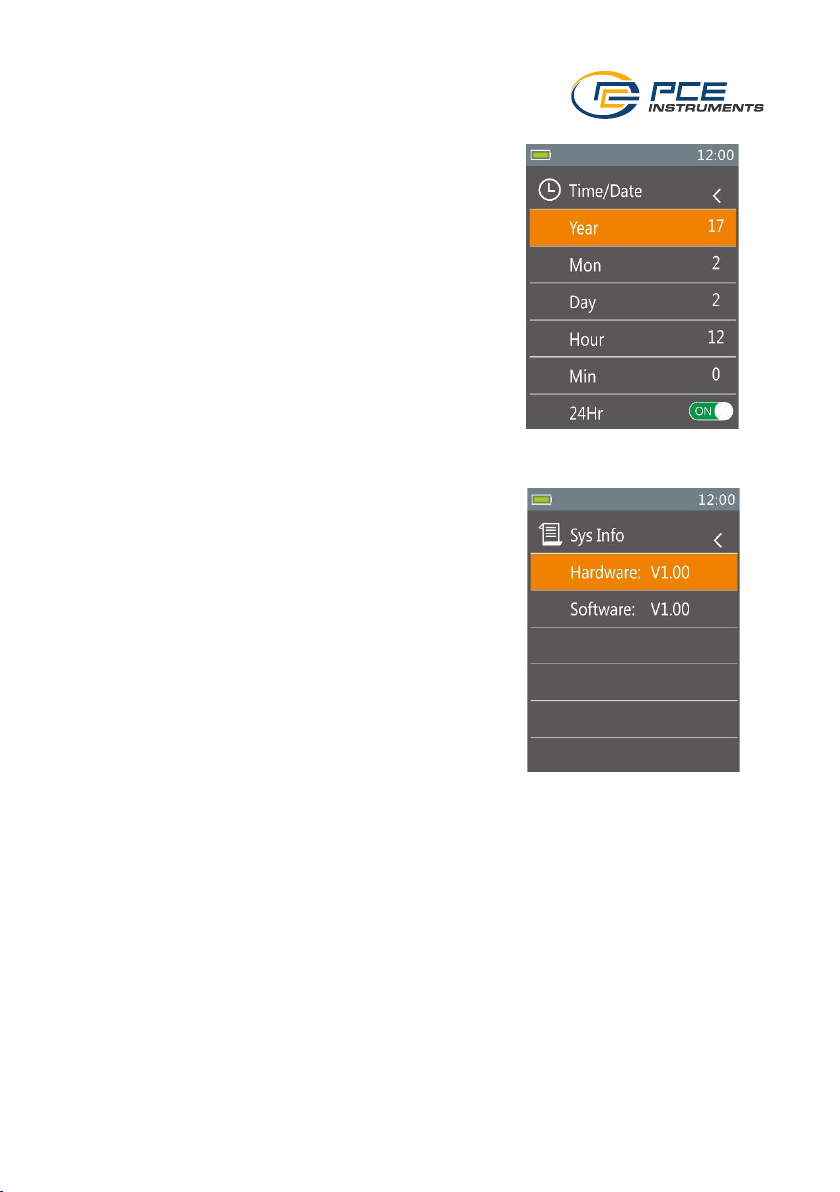
6.4 Set system time and date
The system time can be set in the "Time/Date" menu item.
6.5 Device information
The current hardware version and firmware version are
displayed in the "Information" menu item.
6.6 Call up screenshots
To retrieve the screenshots of the "Hold" function, go to "Memory" in the settings. The screenshots
can be called up and deleted from there.
Note: Up to 16 screenshots can be saved.
Page 22
© PCE Instruments
20
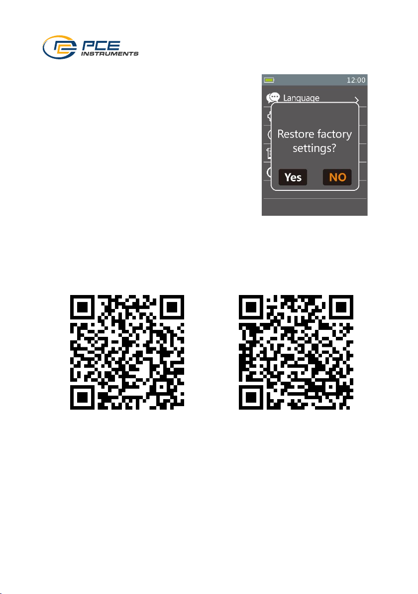
6.7 Restore factory settings
To reset the meter, select "Factory Set" in the menu. You will
then be asked whether you really want to reset the meter.
Confirm this if you do.
7 Bluetooth connection
To establish a Bluetooth connection, first download the free "MeterBox Pro" app from the App
Store or Play Store. Activate the Bluetooth connection of the clamp meter and your mobile device.
Then open the app and connect to the meter via the app.
Note: The connection must not be established via the Bluetooth setting on your mobile end
device.
Android
iOS
Page 23
© PCE Instruments
21
8 Contact
If you have any questions, suggestions or technical problems, please do not hesitate to contact
us. You will find the relevant contact information at the end of this user manual.
9 Disposal
For the disposal of batteries in the EU, the 2006/66/EC directive of the European Parliament
applies. Due to the contained pollutants, batteries must not be disposed of as household waste.
They must be given to collection points designed for that purpose.
In order to comply with the EU directive 2012/19/EU we take our devices back. We either re-use
them or give them to a recycling company which disposes of the devices in line with law.
For countries outside the EU, batteries and devices should be disposed of in accordance with
your local waste regulations.
If you have any questions, please contact PCE Instruments.
Page 24

© PCE Instruments
22
PCE Instruments contact information
Germany France Spain
PCE Deutschland GmbH PCE Instruments France EURL PCE Ibérica S.L.
Im Langel 26 23, rue de Strasbourg Calle Mula, 8
D-59872 Meschede 67250 Soultz-Sous-Forets 02500 Tobarra (Albacete)
Deutschland France España
Tel.: +49 (0) 2903 976 99 0 Téléphone: +33 (0) 972 3537 17 Tel. : +34 967 543 548
Fax: +49 (0) 2903 976 99 29 Numéro de fax: +33 (0) 972 3537 18 Fax: +34 967 543 542
[email protected] [email protected] [email protected]
www.pce-instruments.com/deutsch www.pce-instruments.com/french www.pce-instruments.com/espanol
United Kingdom Italy Turkey
PCE Instruments UK Ltd PCE Italia s.r.l. PCE Teknik Cihazları Ltd.Şti.
Trafford House Via Pesciatina 878 / B-Interno 6 Halkalı Merkez Mah.
Chester Rd, Old Trafford 55010 Loc. Gragnano Pehlivan Sok. No.6/C
Manchester M32 0RS Capannori (Lucca) 34303 Küçükçekmece - İstanbul
United Kingdom Italia Türkiye
Tel: +44 (0) 161 464902 0 Telefono: +39 0583 975 114 Tel: 0212 471 11 47
Fax: +44 (0) 161 464902 9 Fax: +39 0583 974 824 Faks: 0212 705 53 93
[email protected] [email protected] [email protected]
www.pce-instruments.com/english www.pce-instruments.com/italiano www.pce-instruments.com/turkish
The Netherlands United States of America Denmark
PCE Brookhuis B.V. PCE Americas Inc. PCE Instruments Denmark ApS
Institutenweg 15 1201 Jupiter Park Drive, Suite 8 Birk Centerpark 40
7521 PH Enschede Jupiter / Palm Beach 7400 Herning
Nederland 33458 FL Denmark
Telefoon: +31 (0)53 737 01 92 USA Tel.: +45 70 30 53 08
[email protected] Tel: +1 (561) 320-9162 [email protected]
www.pce-instruments.com/dutch Fax: +1 (561) 320-9176 www.pce-instruments.com/dansk
[email protected]
www.pce-instruments.com/us
 Loading...