

Page 1
© PCE Instruments
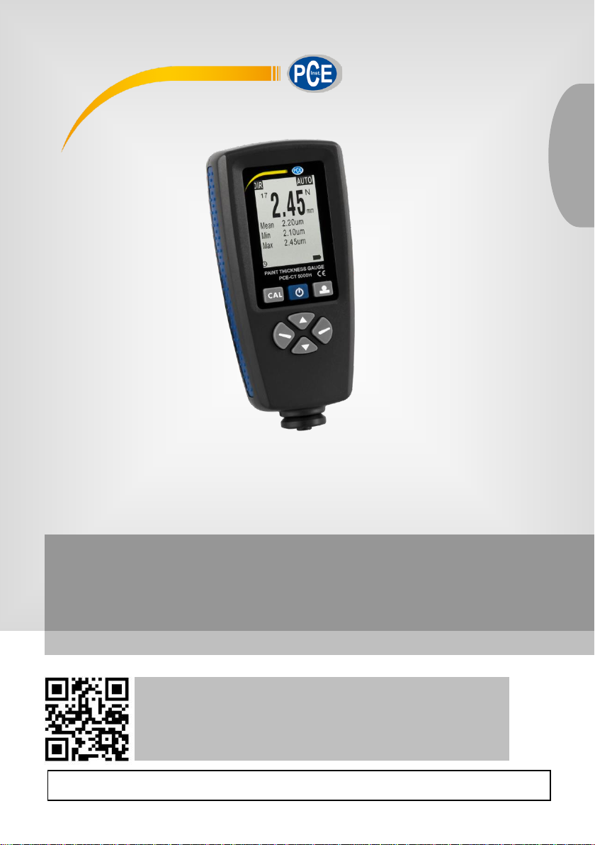
PCE-CT 5000H Coating Thickness Gauge
User Manual
User manuals in various languages (français,
italiano, español, português, nederlands, türk, polski,
русский, 中文) can be found by using our
product search on: www.pce-instruments.com
Last change: 27 May 2020
v1.0
English
Page 2

Contents
1 Safety notes ........................................................................................... 1
2 Introductions ......................................................................................... 2
2.1 Features ........................................................................................................................... 2
2.2 Application ....................................................................................................................... 2
2.3 Principle of Measurement ................................................................................................. 2
2.4 Delivery contents .............................................................................................................. 3
3 Device description ................................................................................ 3
4 Specifications ........................................................................................ 4
5 Use the Gauge ....................................................................................... 5
5.1 Replacing the Battery ....................................................................................................... 5
5.2 Basic Measurement Step ................................................................................................. 5
5.3 User Interface .................................................................................................................. 6
5.4 Measure Mode (Only Support Single Mode) ..................................................................... 7
5.5 Group Mode ..................................................................................................................... 7
5.6 Statistics .......................................................................................................................... 7
5.7 Probe Mode ..................................................................................................................... 8
5.8 Storage ............................................................................................................................ 8
5.9 Recall and Delete Readings ............................................................................................. 8
5.10 High and Low Limit Alarm................................................................................................. 9
5.11 Unit .................................................................................................................................10
5.12 Speed .............................................................................................................................10
5.13 Data Download................................................................................................................10
5.14 Auto Power off.................................................................................................................10
5.15 Measurement Accuracy ...................................................................................................11
6 Factors Affecting Measurement Accuracy ....................................... 11
7 Calibration ........................................................................................... 12
8 Troubleshooting .................................................................................. 14
9 Software ............................................................................................... 15
10 Contact ............................................................................................... 18
11 Disposal ............................................................................................... 18
© PCE Instruments
Page 3

© PCE Instruments
1
1 Safety notes
Please read this manual carefully and completely before you use the device for the first time. The
device may only be used by qualified personnel and repaired by PCE Instruments personnel.
Damage or injuries caused by non-observance of the manual are excluded from our liability and
not covered by our warranty.
• The device must only be used as described in this instruction manual. If used otherwise,
this can cause dangerous situations for the user and damage to the meter.
• The instrument may only be used if the environmental conditions (temperature, relative
humidity, …) are within the ranges stated in the technical specifications. Do not expose
the device to extreme temperatures, direct sunlight, extreme humidity or moisture.
• Do not expose the device to shocks or strong vibrations.
• The case should only be opened by qualified PCE Instruments personnel.
• Never use the instrument when your hands are wet.
• You must not make any technical changes to the device.
• The appliance should only be cleaned with a damp cloth. Use only pH-neutral cleaner,
no abrasives or solvents.
• The device must only be used with accessories from PCE Instruments or equivalent.
• Before each use, inspect the case for visible damage. If any damage is visible, do not
use the device.
• Do not use the instrument in explosive atmospheres.
• The measurement range as stated in the specifications must not be exceeded under
any circumstances.
• Non-observance of the safety notes can cause damage to the device and injuries to
the user.
We do not assume liability for printing errors or any other mistakes in this manual.
We expressly point to our general guarantee terms which can be found in our general terms of
business.
If you have any questions please contact PCE Instruments. The contact details can be found at
the end of this manual.
Page 4

© PCE Instruments
2
2 Introductions
This compact gauge can be used for non-destructive coating thickness measurement of nonmagnetic coatings, e.g. paint, enamel, chrome on steel, and insulating coatings, e.g. paint and
anodizing coatings on non-ferrous metals.
2.1 Features
• 128* 128 dot matrix LCD display, standard menu operations;
• Two measure mode: single and continuous;
• Two group mode:direct(DIR) and general(GEN), readings will be lost when power off
in direct mode, and not be
• lost in general mode. Readings can be stored for each group;
• Zero point calibration and multi-point calibration(up to 4 points) for each group;
• User can recall, delete specified readings, or delete group readings;
• Statistics display: mean, minimum, maximum and standard deviation;
• Three probe mode:auto, magnetic and eddy current;
• User can set high or low limit alarm for each group;
• Power off automatically;
• USB interface to data transmission;
• Low battery and error indication ;
2.2 Application
This gauge is designed for non-destructive, fast and precise coating thickness measurement. The
principal applications lie in the field of corrosion protection. It is ideal for manufacturers and their
customers, for offices and specialist advisers, for paint shops and electroplaters, for the chemical,
automobile, ship building and aircraft industries and for heavy engineering. It is suitable for
laboratory, workshop and outdoor use.
2.3 Principle of Measurement
The coating thickness gauge work either on the magnetic induction principle or on the eddy
current principle, depending on the type of probe used. This gauge has internal F probe and N
probe.
F probe work on magnetic induction principle and should be used for non-magnetic coatings
such as aluminium, chrome, copper, zinc, paint and varnish, enamel, rubber etc., on an iron or
steel substrate; It is also suitable for alloyed and hardened magnetic steel (however, not
suitable for austenitic steel).
N Probe work on the eddy current principle and should be used for insulating coatings e. g.
paint, anodizing, ceramics, etc., on all non-ferrous metals such as aluminium, copper, zinc die
casting, brass etc. and on austenitic stainless steels.
Page 5
© PCE Instruments
3
2.4 Delivery contents
1 x PCE-CT 5000H thickness gauge
2 x Zero calibration plates (ferrous and non-ferrous)
5 x Calibration plates
2 x 1.5V AAA batteries
1 x USB cable
1 x PC-compatible software
1 x User manual
1 x Carrying case
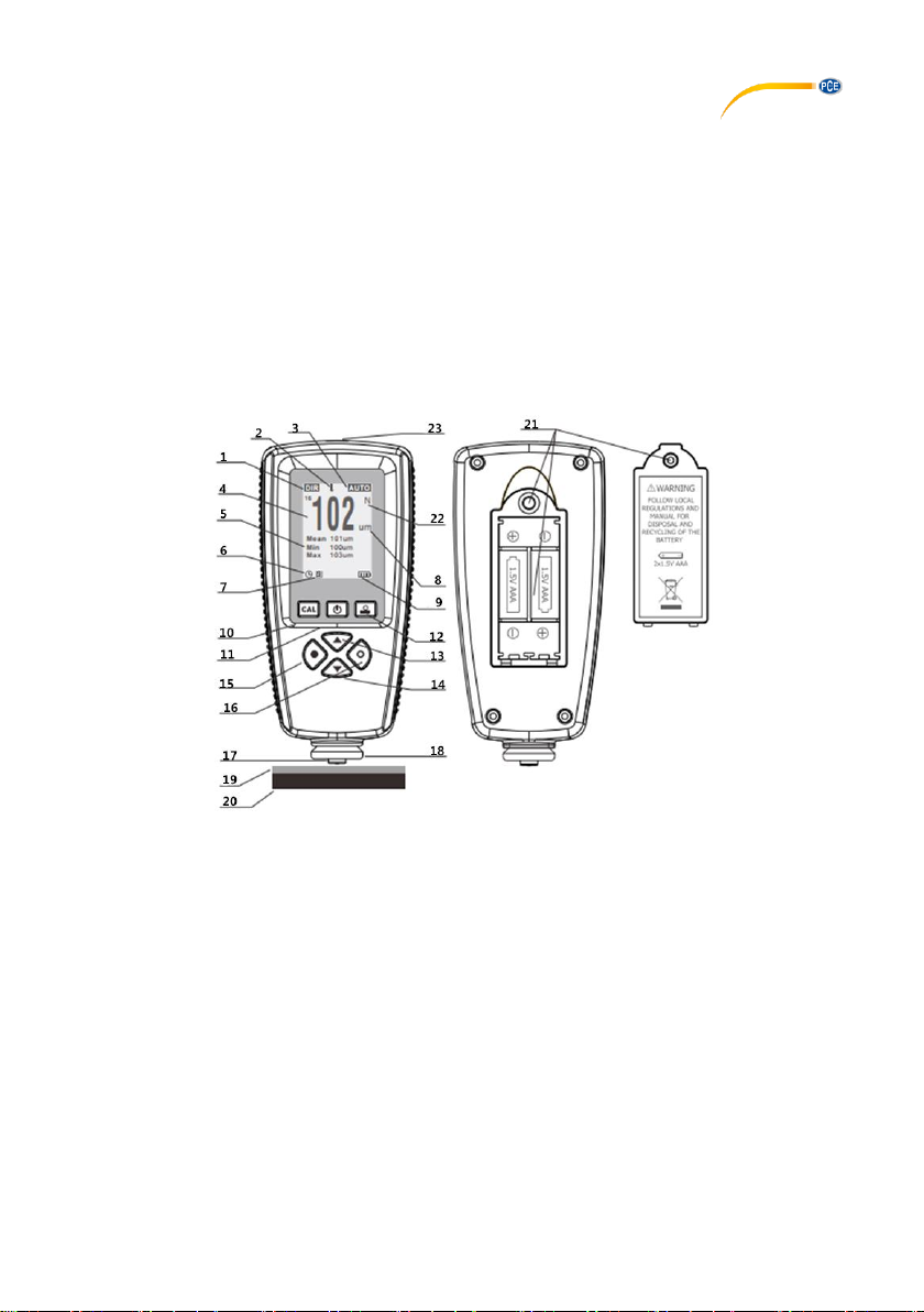
3 Device description
1. Measurement mode
2. High and low limit alarm
3. Probe mode: AUTO, MAG, EDDY
4. Measuring readings display
5. Statistics display (MIN/MAX/AVG)
6. Auto-power off indication
7. USB connecting indication
8. Measuring unit
9. Low battery indication
10. Calibration key
11. POWER on/off key
12. ZERO calibration key
13. UP key
14. DOWN key
15. LEFT key
16. RIGHT key
17. Probe
18. V groove
19. Standard foil
20. Substrate
21. Battery compartment
22. Material recognition (F: ferrous;N: non ferrous)
23. USB interface for PC connection
Page 6

© PCE Instruments
4
4 Specifications
Probe
Type F and Type N
Measuring range Type
F
0 ... 5000 μm / 0 ... 5 mm / 0 ... 196 mils
Measuring accuracy
Type F
± (2% + 1 μm)
Resolution Type F
0 ... 99.9 μm: 0.1 μm, 100 ... 999 μm: 1 μm
> 1000 μm: 0.01 mm
Measuring principle
Type F
Magnetic induction
Smallest thickness of
the base material
0.02 mm
Measuring range Type
N
0 ... 3000 μm / 0 ... 3 mm / 0 ... 118 mils
Measuring accuracy
Type N
± (2% + 1 μm)
Resolution Type N
0 ... 99.9 μm: 0.1 μm, 100 ... 999 μm: 1 μm
> 1000 μm: 0.01 mm
Measuring principle
Type N
Eddy current
Smallest thickness of
the base material
0.05 mm
Calibration
One-point to four-point calibration, zero calibration
Data storage
Direct measurement (no measurement data storage), four data
groups (automatic measurement data storage of up to 2000
measured values)
Statistical functions
Number of measurements, average, minimum, maximum,
standard deviation
Measurement units
μm, mm, mils
Alarm
Alarm limits adjustable, alarm symbol is displayed when limits are
exceeded
Minimum radius of
curvature (convex)
5 mm / 0.2 in
Minimum radius of
curvature (concave)
25 mm / 1 in
Smallest measuring
surface
Diameter of 20 mm / 0.8 in
Maximum measuring
rate
2 x per second
Data interface
Data transfer via USB
Power supply
2 x 1.5V AAA batteries
Menu languages
German, English, Russian, Chinese
Operating conditions
0 ... 50°C / 32 ... 122°F, 20 ... 90% RH
Storage conditions
-10 ... 60°C / 14 ... 140°F
Standards
CE ROHS FCC
Dimensions
110 x 53 x 24 mm / 4.33 x 2.09 x 0.95 in
Material housing
ABS plastic
Weight
92 g / < 1 lb
Page 7

© PCE Instruments
5
5 Use the Gauge
If you use the gauge for the first time, please read the chapter 6 Factors Affecting Measurement
Accuracy.
5.1 Replacing the Battery
Place the gauge upside down on a suitable surface, remove the screws from the battery
compartment with a crosstip screwdriver, raise the lid of the compartment, remove battery,
insert new battery according to the positive and negative poles and close the lid and fasten with
screws.
5.2 Basic Measurement Step
Step 1: Prepare the sample to be measured.
Step 2: Press power to start the instrument.
Note:
1. If a full battery displayed, the battery is OK. Or if a low battery displayed, the battery capacity
is low, and measurement will be not reliable, and you need to replace the battery.
2. The gauge will work in factory default settings for the first time, including single measure
mode, AUTO probe mode, direct group mode (DIR) etc..
3. When power on, if in direct group mode (DIR), the readings display area is empty, or if in
general group mode (GENn, n=1 to 4), it will display the last readings and statistics value
measured before power off last time.
Step 3: Refer to chapter 6 Factors Affecting Measurement Accuracy to decide whether you
need to calibrate the gauge.
Step 4: Start measuring. Place the probe on the sample vertically and rapidly, and after one
beep (for single measure mode), raise the probe rapidly. Readings will display on LCD,
meanwhile statistics values are upgraded and displayed.
Step 5: Do next measurement according to step 4.
Step 6: Press power off. If not any operations within 3 min., the gauge will power off
automatically.
Note:
1. If a suspicious reading is measured, user can delete it by pressing the UP key once.
Page 8
© PCE Instruments
6
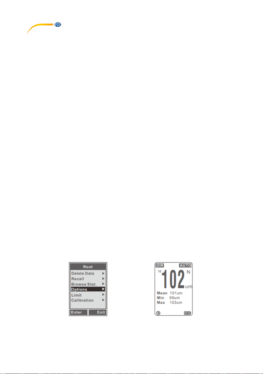
5.3 User Interface
The gauge has a standard user interface for easy use.
• Left Key
a. To enter into menu mode from measure mode;
b. Left button operations in menu mode (Including “Sure”, “Select”, “Delete”);
• Right Key
a. Right button operations in menu mode(Including “Cancel”, “Back”, “Exit”);
b. Switch on/off the backlight in measure mode;
• Up Key
a. Move up or roll up;
b. Increasing;
c. Delete the last readings or whole group
• Down Key
a. Move down or roll down;
b. Decreasing; c. Refresh LCD on the main interface
• Zero Calibration Key
a. Press and hold to do zero calibration;
c. Press once to back measure mode in menu mode;
d. Press and hold when power on to make system reset.
This will restore factory settings;
• Calibration Key
a. Enter into calibration mode and back measure mode;
Page 9

© PCE Instruments
7
5.4 Measure Mode (Only Support Single Mode)
Single measure mode - Place the probe on sample vertically and rapidly, and after one beep,
raise it rapidly.
5.5 Group Mode
• Direct Group (DIR)-Be intended for quick occasional readings. In this mode, data are
temporarily stored in RAM, it will be lost when power off. The readings and statistics
can be shown on the LCD. When the RAM is full, measuring will continue, the oldest
readings will be deleted mean while the new readings is stored. Each new readings is
stored, the statistics will be upgraded and shown.
• General Group (GENn, n=1 to 4)-In this mode, data are stored in memory and not lost
when power off. When the memory is full, measuring will continue, a “fl” will be shown
on the left of readings, the new readings will not be stored, and statistics will not be
upgraded.
Note: Each group (DIR or GEN) has individual high/low limit alarm, zero calibration and
multi-point calibration,and these settings will stored in memory when user changes them.
• Method of switch group mode
a. Press “Left Key” once to enter into menu mode (”Root” directory);
b. Press “Up Key” or “Down Key” to activate “Options” item, and press “Left Key” once
to enter in;
c. Press “Up Key” or “Down Key” to activate ”Group Mode” item, and press “Left Key”
once to enter in;
d. Press “Up Key” or “Down Key” to activate your intended item, and press “Left Key”
once to select the item and go back. Press “ZERO Key” to back measure mode.
5.6 Statistics
The gauge calculates the statistics for stored readings of each group independently, including
mean, minimum, maximum and standard deviation. In direct group mode, when RAM is full, the
oldest readings will be deleted meanwhile the new readings will be stored, and the statistics will
be upgraded. In general group mode, when memory is full, new readings will not be stored and
the statistics will not be upgraded. If user deletes the specified readings or whole group readings,
the statistics will also be upgraded.
• Browse the statistics through menu
a. Press “Left Key” once to enter into menu mode (”Root” directory);
b. Press “Up Key” or “Down Key” to activate “Browse Stat.” item, and press “Left Key”
once to enter in;
c. Press “Right Key” once to go back. Press “ZERO Key” to back measure mode.
Page 10

© PCE Instruments
8
5.7 Probe Mode
There are three probe modes: AUTO, MAG and EDDY. In AUTO mode, the probe can
automatically determine the type of substrate measured. In MAG mode, the probe can only
measure on magnetic substrates. In EDDY mode, the probe can only measure on non-ferrous
metal substrates. When a magnetic substrate detected, an “F” will be shown on the right of
readings, and when a non-ferrous metal detected, a “N” will be shown. User can switch probe
mode as below.
a. Press “Left Key” once to enter menu mode (”Root” directory).
b. Press “Up Key” or “Down Key” to activate “Options” item, and press “Left Key” once to enter.
c. Press “Up Key” or “Down Key” to activate ”Probe Mode” item, and press “Left Key” once to
enter.
d. Press “Up Key” or “Down Key” to activate your intended item, and press “Left Key” once to
select the item and go back. Press “ZERO Key” to back measure mode.
5.8 Storage
In general group mode (GENn), readings and statistics will be stored and not be lost when
power off. In direct group mode (DIR), readings and statistics will be lost when power off.
Each group has individual high/low limit alarm, zero calibration and multi-point calibration, user
can change these settings, and they will be stored.
In addition, user can set the system settings (e.g.: Measure Mode,Group Mode,Probe Mode
etc.), these settings will also be stored.
Note: When battery low, user must replace the battery timely. Before replacing the battery, you
need to power off the gauge firstly.
5.9 Recall and Delete Readings
• Delete the last readings (Tips: If in measure mode, press the “UP Key” once by one
beep).
a. Press “Left Key” once to enter menu mode (”Root” directory).
b. Press “Up Key” or “Down Key” to activate “Delete Data” item, and press “Left Key”
once to enter.
c. Press “Up Key” or “Down Key” to activate ”Current Data” item, and press “Left Key”
once. A dialog box will be displayed.
d. Press “Left Key” once to confirm the selection and go back, or “Right Key” to cancel
and back. Press “ZERO Key” to go back to measure mode.
Page 11

© PCE Instruments
9
• Delete whole group readings (Tip: If in measure mode, hold the “UP Key” by one beep)
a. Press “Left Key” once to enter menu mode (”Root” directory).
b. Press “Up Key” or “Down Key” to activate “Delete Data” item, and press “Left Key”
once to enter.
c. Press “Up Key” or “Down Key” to activate ”Current Group” item, and press “Left
Key” once. A dialog box will be displayed.
d. Press “Left Key” once to confirm the selection and go back, or “Right Key” to cancel
and back. Press “ZERO Key” to go back to measure mode.
• Recall and delete specified readings
a. Press “Left Key” once to enter menu mode (”Root” directory).
b. Press “Up Key” or “Down Key” to activate “Recall” item, and press “Left Key” once
to enter.
c. Press “Up Key” or “Down Key” to recall the readings (n/Total number, “n” indicates
the index of currently shown readings). User can press “Left Key” to delete
currently shown readings.
d. Press “Right Key” to go back. Press “ZERO Key” to go back to measure mode.
Note: While readings deleted, the statistics will be upgraded automatically.
5.10 High and Low Limit Alarm
Each group has individual high/low limit alarm settings. When you switch the work group, the
applied alarm settings will also be switched automatically.
• Set high/low limit for the current work group as below.
a. Press “Left Key” once to enter menu mode (”Root” directory).
b. Press “Up Key” or “Down Key” to activate “Limit” item, and press “Left Key” once to
enter.
c. Press “Up Key” or “Down Key” to activate “Settings” item, and press “Left Key” once
to enter.
d. Press “Up Key” or “Down Key” to activate your intended item, and press “Left Key”
once to enter.
e. Press “Up Key” or “Down Key” to increase or decrease the limit value. If you hold
the key, the limit value will be increased or decreased continuously.
f. Press “Left Key” to confirm new limit value, or “Right Key” to cancel and back. Press
“ZERO Key” to go back to measure mode.
• Clear high/low limit
a. Press “Left Key” once to enter menu mode(”Root” directory);
b. Press “Up Key” or “Down Key” to activate “Limit” item, and press “Left Key” once to
enter.
c. Press “Up Key” or “Down Key” to activate ”Clear” item, and press “Left Key” once. A
dialog box will be displayed.
d. Press “Left Key” once to confirm the selection and go back, or “Right Key” to cancel
and back. Press “ZERO Key” to go back to measure mode.
Note:While readings exceed high limit, the alarm symbol will be shown on the LCD, and while
readings exceed low limit, the alarm symbol will be shown.
Page 12

© PCE Instruments
10
5.11 Unit
User can select the shown unit (including µm, mm and mils) for the readings. Switch the unit as
below.
a. Press “Left Key” once to enter menu mode (”Root” directory).
b. Press “Up Key” or “Down Key” to activate “Options” item, and press “Left Key” once to enter.
c. Press “Up Key” or “Down Key” to activate ”Unit Settings” item, and press “Left Key” once to
enter.
d. Press “Up Key” or “Down Key” to select intended item. Press “Left Key” to confirm it.
5.12 Speed
Generally, The faster the measuring speed for probe, the worse accuracy. User can select
different measuring speed for probe according to user’s application fields as below:
a. Press “Left Key” once to enter menu mode(”Root” directory).
b. Press “Up Key” or “Down Key” to activate “Options” item, and press “Left Key” once to enter.
c. Press “Up Key” or “Down Key” to activate ”Speed” item, and press “Left Key” once to enter.
d. Press “Up Key” or “Down Key” to select intended item. Press “Left Key” to confirm it.
5.13 Data Download
User can use the USB cable to connect the gauge with PC and download stored readings. If USB
connected, the symbol will be shown on the bottom of the LCD. When USB connected firstly, the
PC need to install driver and software for this application. User can get the driver and software
from our website.
5.14 Auto Power off
User can power off via key manually. In addition, for save power, the gauge will turn off
automatically in default if not any operations. Before turn off automatically, user will hear several
beeps, and then user can press timely any key to let the gauge restart timing and continue
working. Enable or Disable this function as below.
a. Press “Left Key” once to enter menu mode (”Root” directory);
b. Press “Up Key” or “Down Key” to activate “Options” item, and press “Left Key” once to enter.
c. Press “Up Key” or “Down Key” to activate “Auto Poweroff” item, and press “Left Key” once to
enter.
d. Press “Up Key” or “Down Key” to select intended item. Press “Left Key” to confirm it.
Page 13

© PCE Instruments
11
5.15 Measurement Accuracy
Factors of affecting measurement accuracy, please reference the chapter 6 Factors Affecting
Measurement Accuracy. Under normal use and careful calibration, all subsequent
measurements will lie within the guaranteed measuring tolerance. When using the statistics
programmer for obtaining a mean value it is advisable to place the probe several times at a
typical measuring spot or at fixed measuring spot.
Any false readings or outliers can be deleted immediately. The final reading derives from the
statistical calculation and from the guaranteed tolerance levels of the gauge.
T(coating thickness)=M(mean value)±S(standard deviation)±A(measuring accuracy).
6 Factors Affecting Measurement Accuracy
User needs to know the factors of affecting measurement accuracy before using the gauge.
The factors are listed below.
Factors Principle
Magnetic
Eddy Current
Recommendations
Magnetic properties
√ Need to calibrate
Electrical properties
√ Need to calibrate
Curvature radius
√ √ See specifications and calibrate
Substrate thickness
√ √ See specifications and calibrate
Size of measuring area
√ √ See specifications and calibrate
Surface roughness
√ √
Position and shape
√ √
Sample deformed
√ √ Avoid to measure on too soft or too thin
material
Adhesive substances
√ √ Clean probe and sample
Strong magnetic field
√ Be away from strong magnetic field
Temperature and
humidity
√ √ Recalibrate at the same environment
conditions
Measuring operations
√ √ Read the chapter 5.2 Basic Measurement Step
Low battery
√ √ Replace the battery
Probe wear
√ √ Contact PCE Instruments
Page 14

© PCE Instruments
12
The measured sample must correspond to the calibration sample in substrate material properties,
curvature radius, or the more closely the measured sample matches the calibration sample, the
more accurate the measuring. In addition, curvature radius should meet the minimum value as
specified in the specifications.
The minimum substrate thickness and the minimum measuring areas as specified in the
specifications should be taken into account. Need to recalibrate (Zero/Multi-point) for different
measured sample for higher accuracy.
To achieve high-accuracy readings, it is advisable to log calibration values several times. In this
way, the gauge will automatically establish a mean calibration value. The high-accuracy
calibration is an obvious advantage when calibrating on uneven and rough surfaces.
The point at which measurement is made should always be similar with the calibration point,
especially in the case of corners and edges of small parts.
Important Note: The enclosed substrates are intended for checking accuracy only and not for
calibration purposes. User must recalibrate the gauge according to practical applications.
7 Calibration
User should read chapter 6 Factors Affecting Measurement Accuracy firstly, and must
recalibrate the gauge according to measured product sample. The gauge provid es basic
calibration, zero calibration and multi-point calibration.
• Basic calibration: Also be the factory default calibration, can only for measurement on
even surfaces and if the measuring object has the same material, curvature, and size
as the factory provided substrates. For more details, please consult with your
supplier.
• Zero calibration: Recommended if measuring errors up to ± (2%+1um).
• Multi-point calibration: The permitted measuring errors will be max. ± (1~2%+1um). If
only one point calibration, it is recommended if readings to be expected will be close
to the calibration value. If more than one point calibration, it is recommended for
measurements on rough surfaces or for precise measurements on smooth surfaces if
thickness to be expected lies between that of calibration point.
Zero Calibration
a. Press and hold “ZERO Key” until hearing “beep...beep beep...”. The LCD will flash “ZERO”
symbol.
b. Place the probe on uncoated sample and raise it after one beep.
c. Repeat step b and c several times to obtain mean value.
d. Finished. Press “ZERO Key” to exit calibration mode.
Page 15

© PCE Instruments
13
Multi-point Calibration
a. In measure mode, press “CAL key” once to enter calibration mode.
b. Zero calibration according to the previous chapter and then lay the calibration foil on an
uncoated sample.
c. Apply the probe and raise it after one beep. A reading will be shown. Press “Up Key” or
“Down Key” to increase or decrease the readings or hold the key for changing continuously
until the required foil thickness value shown. The LCD will show current calibration point
“Ptn X ”. The “X” will be flashing.
d. Apply the probe to the test sample several times, and every time raise the probe, if you press
“CAL Key”, after “beep...beep beep...”, it will establish a mean value for current calibration
point.
e. Press “Left Key” to confirm and end current calibration point, and the “X” will be steady. Or
press “Right Key” to cancel and end current calibration point.
f. For more calibration points, use another calibration foil and repeat the step c, d and e.
g. Finished. Press “CAL Key” to exit calibration mode.
Note:
a. Each group has individual zero calibration and multi-point calibration.
b. When calibration up to 4 points, user must clear the finished points firstly to restart.
c. Readings measured before will not be affected by new calibration.
d. In calibration mode, measuring will not be affected.
e. Recommended to work in single measure mode when calibrating.
Shot-blasted surfaces
The physical nature of shot-blasted surfaces results in coating thickness readings that are too
high. The mean thickness over the peaks can be determined as follows.
Method one:
a. The gauge should be calibrated according to “Multi-point Calibration”. Use a
smooth calibration sample with the same curvature radius and the same substrate as the
later measuring sample.
b. Take approx. 10 readings on the uncoated, shot-blasted sample to produce mean value A.
c. Take approx. 10 further readings on the coated, shot-blasted test sample to produce mean
value B.
d. The coating thickness is T=(B-A)±S. The “S” is the greater standard deviation of step b and
step c.
Method two:
a. The gauge should be calibrated according to “Multi-point Calibration” on the shot
blasted sample.
b. Take approx. 10 readings on the test sample to produce the mean value that used as final
coating thickness.
Page 16

© PCE Instruments
14
Clear Calibration
User can clear calibration to start new applications. When the values are still out of tolerance, the
user should clear it.
a. Press “Left Key” once to enter menu mode (”Root” directory).
b. Press “Up Key” or “Down Key” to activate “Calibration” item, and press “Left Key” once to
enter.
c. Press “Up Key” or “Down Key” to activate ”Clear All” item (Note: User can decide to clear only
part of them, please see the menu for details), and press “Left Key” once. A dialog box will be
displayed.
d. Press “Left Key” once to confirm the selection and go back, or “Right Key” to cancel and
back.
Note:
All operations are limited in current work group, and the other groups will not be affected.
8 Troubleshooting
If the instrument gives no response and can’t be turned on, you can remove the battery, and a
few minutes later, reinstall the battery, and try again. If the problem persists, please contact
PCE Instruments for help.
The following errors can be remedied by system reset:
-Illogical readings
-Several of the keys don’t work
System reset:
1. Power off the gauge.
2. Press and hold “ZERO Key” and then power on the gauge.
3. Release the “ZERO Key” until a dialog box of system reset shown on the LCD.
4. Press “Left Key” to confirm system reset. The gauge will restart automatically.
Errata:
1. User can press the “Down Key” to refresh LCD display (Clear error display) and reset probe
(To speed up the probe stability) in measuring mode.
2. If an error is shown in menu mode, the user can re-enter the menu.
Page 17
© PCE Instruments
15
9 Software
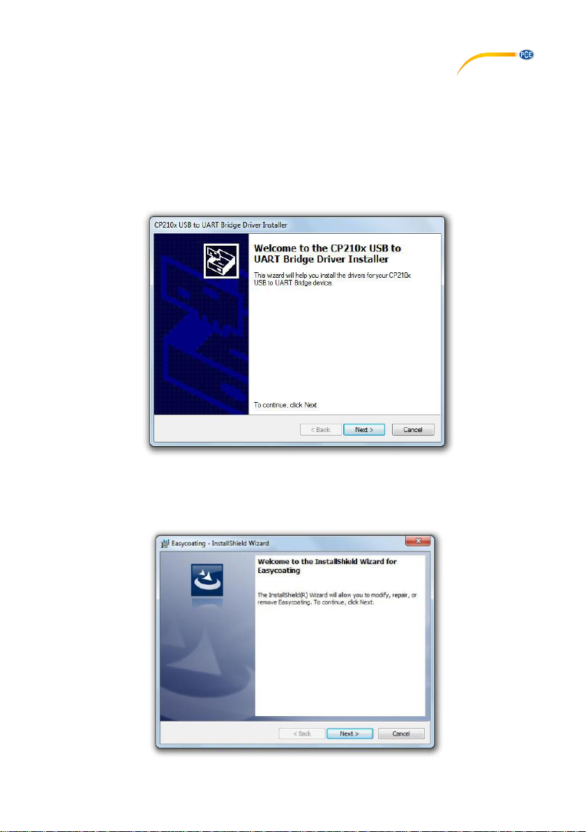
1. Insert the CD into your CD-ROM drive.
2. Open the following file directory on the CD:
EasyCoating V1.4\Driver\CP210x_Windows
3. Open the file "CP210xVCPInstaller_x86.exe" (for 32 bit operating system) or
"CP210xVCPInstaller_x64.exe" (for 64 bit operating system) and install it.
4. Then open the following file directory on the CD:
EasyCoating V1.4\Setup\EasyCoating Basic English
5. Open the "Setup.exe" and install the software.
Page 18
© PCE Instruments
16
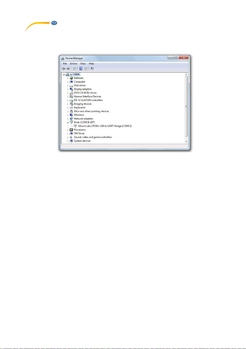
6. Connect the device via USB. Now open the Device Manager and expand
the item "Ports (COM & LPT)". Here you can now see the COM port required for the software.
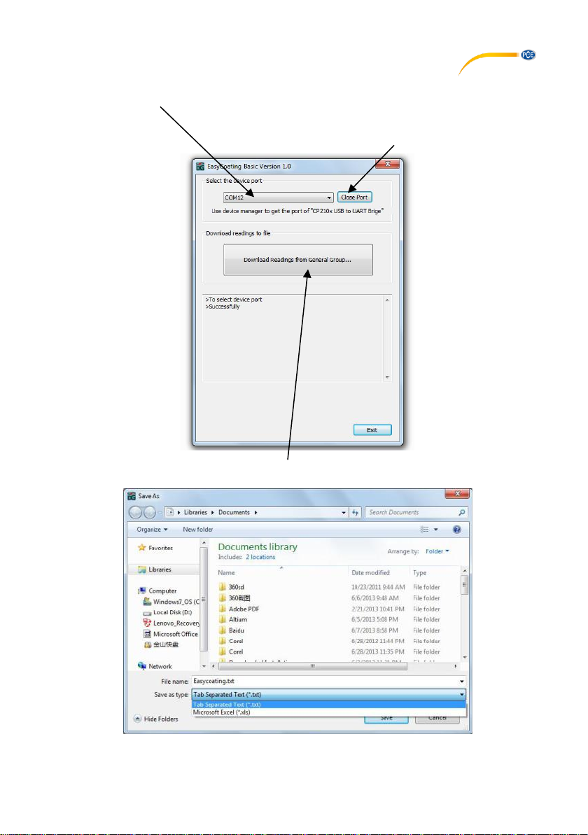
7. Start the installed programme (EasyCoating) to download the measured values.
Follow these steps:
Page 19
© PCE Instruments
17
Step 1: Select COM port
Step 2: To establish a connection, click on
“Open Port“. When you are successfully
connected, “successfully“ will be displayed in
the lower half of the window.
Step 3: Click on “Download Readings…“ to download the measured values.
Step 4: Save the measured values.
Page 20
10 Contact
If you have any questions, suggestions or technical problems, please do not hesitate to contact
us. You will find the relevant contact information at the end of this user manual.
11 Disposal
For the disposal of batteries in the EU, the 2006/66/EC directive of the European
Parliament applies. Due to the contained pollutants, batteries must not be disposed of as
household waste. They must be given to collection points designed for that purpose.
In order to comply with the EU directive 2012/19/EU we take our devices back. We either reuse them or give them to a recycling company which disposes of the devices in line with law.
For countries outside the EU, batteries and devices should be disposed of in accordance
with your local waste regulations.
If you have any questions, please contact PCE Instruments.
© PCE Instruments
18
Page 21

© PCE Instruments
19
PCE Instruments contact information
Germany France Spain
PCE Deutschland GmbH PCE Instruments France EURL PCE Ibérica S.L.
Im Langel 4 23, rue de Strasbourg Calle Mayor, 53
D-59872 Meschede 67250 Soultz-Sous-Forets 02500 Tobarra (Albacete)
Deutschland France España
Tel.: +49 (0) 2903 976 99 0 Téléphone: +33 (0) 972 3537 17 Tel. : +34 967 543 548
Fax: +49 (0) 2903 976 99 29 Numéro de fax: +33 (0) 972 3537 18 Fax: +34 967 543 542
[email protected] [email protected] [email protected]
www.pce-instruments.com/deutsch www.pce-instruments.com/french www.pce-instruments.com/espanol
Germany United Kingdom Italy
PCE Produktions- und PCE Instruments UK Ltd PCE Italia s.r.l.
Entwicklungsgesellschaft mbH Unit 11 Southpoint Business Park Via Pesciatina 878 / B-Interno 6
Im Langel 26 Ensign Way, Southampton 55010 Loc. Gragnano
D-59872 Meschede Hampshire Capannori (Lucca)
Deutschland United Kingdom, SO31 4RF Italia
Tel.: +49 (0) 2903 976 99 471 Tel: +44 (0) 2380 98703 0 Telefono: +39 0583 975 114
Fax: +49 (0) 2903 976 99 9971 Fax: +44 (0) 2380 98703 9 Fax: +39 0583 974 824
[email protected] [email protected] [email protected]
www.pce-instruments.com/deutsch www.pce-instruments.com/english www.pce-instruments.com/italiano
The Netherlands China Hong Kong
PCE Brookhuis B.V. PCE (Beijing) Technology Co., Limited PCE Instruments HK Ltd.
Institutenweg 15 1519 Room, 6 Building Unit J, 21/F., COS Centre
7521 PH Enschede Zhong Ang Times Plaza 56 Tsun Yip Street
Nederland No. 9 Mentougou Road, Tou Gou District Kwun Tong
Telefoon: +31 (0)53 737 01 92 102300 Beijing, China Kowloon, Hong Kong
[email protected] Tel: +86 (10) 8893 9660 Tel: +852-301-84912
www.pce-instruments.com/dutch [email protected] [email protected]
www.pce-instruments.cn www.pce-instruments.cn
United States of America Turkey
PCE Americas Inc. PCE Teknik Cihazları Ltd.Şti.
711 Commerce Way suite 8 Halkalı Merkez Mah.
Jupiter / Palm Beach Pehlivan Sok. No.6/C
33458 FL 34303 Küçükçekmece - İstanbul
USA Türkiye
Tel: +1 (561) 320-9162 Tel: 0212 471 11 47
Fax: +1 (561) 320-9176 Faks: 0212 705 53 93
[email protected] [email protected]
www.pce-instruments.com/us www.pce-instruments.com/turkish
 Loading...