

Page 1
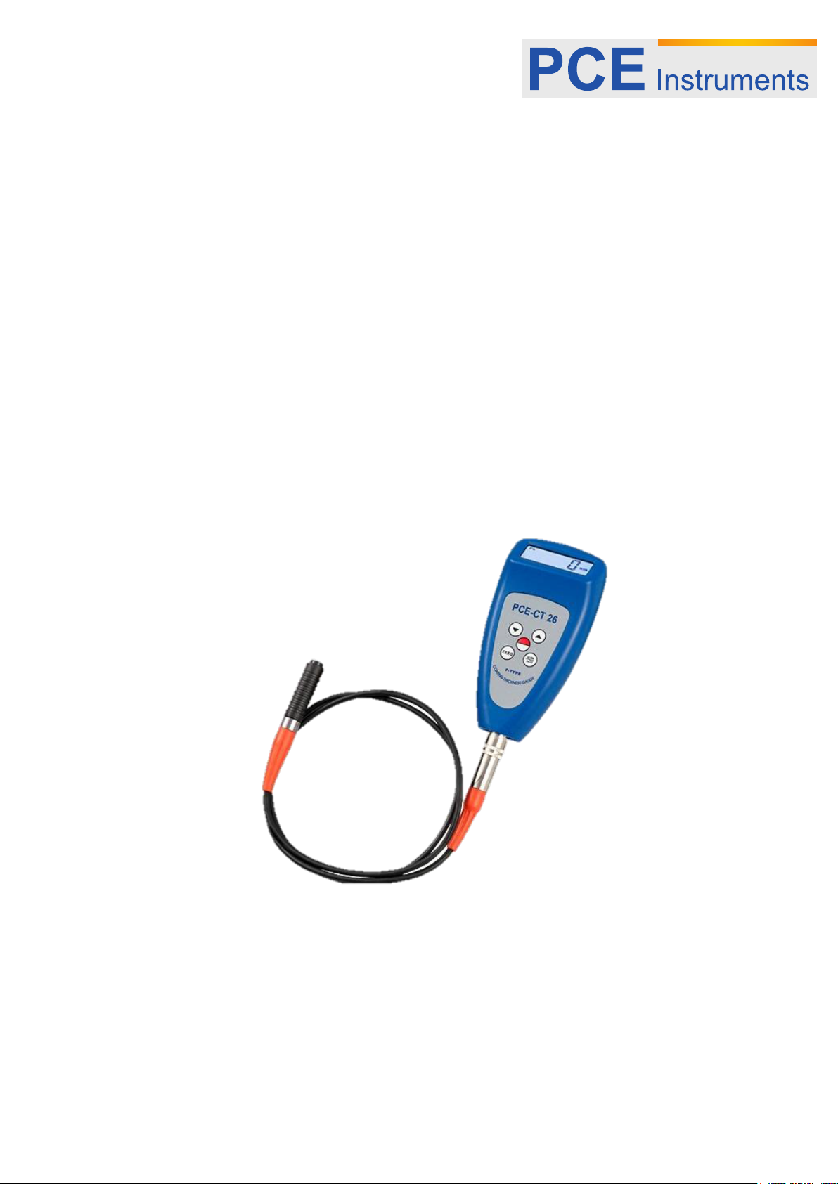
PCE-CT 26
Manual
PCE Americas Inc.
711 Commerce Way
Suite 8
Jupiter
FL-33458
USA
From outside US: +1
Tel: (561) 320-9162
Fax: (561) 320-9176
[email protected]
www.pce-instruments.com/english
www.pce-instruments.com
PCE Instruments UK Ltd.
Units 12/13
Southpoint Business Park
Ensign way
Hampshire / Southampton
United Kingdom, SO31 4RF
From outside UK: +44
Tel: (0) 2380 98703 0
Fax: (0) 2380 98703 9
Page 2

Manual
Table Of Contents
1 Features ................................................................................................................... 3
2 Specifications ........................................................................................................... 3
3 Front Panel Descriptions .......................................................................................... 4
4 Measuring Procedure ............................................................................................... 4
5 Calibration ................................................................................................................ 5
6 Battery Replacement ................................................................................................ 5
7 Considerations ......................................................................................................... 5
8 Restore Factory Settings .......................................................................................... 5
8.1 When to restore? ............................................................................................................................ 5
8.2 How to restore? .............................................................................................................................. 5
9 Notes ........................................................................................................................ 6
Page 3

Manual
1 Features
- It meets the standards of ISO 2178, DIN, ASTM and BS. Suitable for the laboratory and for use in
harsh field conditions
- The F probes measure the thickness of non-magnetic (e.g. paint, plastic, porcelain enamel,
copper, zinc, aluminium, chrome etc.) on magnetic materials (e.g. iron, nickel etc.). Often used to
measure the thickness of galvanizing layer, lacquer layer, porcelain enamel layer, phosphide
layer, copper tile, aluminium tile, some alloy tile, paper etc.
- Automatic substrate recognition
- Manual or automatic shutdown
- Two measurement modes:
o Single
o Continuous
- Wide measuring range and high resolution
- Metric / Imperial conversion
- Digital display gives exact reading with no guessing or errors
- Can communicate with PC for statistics and printing by the optional cable and the software for the
RS-232C interface
2 Specifications
- Display: 4 digits, 10 mm LCD
- Range: 0 … 1250 µm / 0 … 50 mil (other range may be specified)
- Resolution: 0,1 µm (0 … 99.9)
1 µm (over 100 µm)
- Accuracy: ±1 … 3 %n or 2.5 µm or 0.1 mil (whichever is the greater)
- PC interface: with RS-232C
- Power supply: 4 x 1.5 AAA (UM-4) battery
- Operating condition: Temperature: 0 … 50 °C
Humidity: <80 %
- Size: 126 x 65 x 27 mm (5.0 x 2.6 x 1.1 inch)
- Weight: about 100 g (excluding batteries
- Accessories: Carrying case (1x)
Operation manual (1x)
F probe (1x)
Calibration foils (1 set)
Substrate (Iron) (1x)
- Optional accessories: Cable and software for RS-232C
ISO-calibration certificate
Page 4
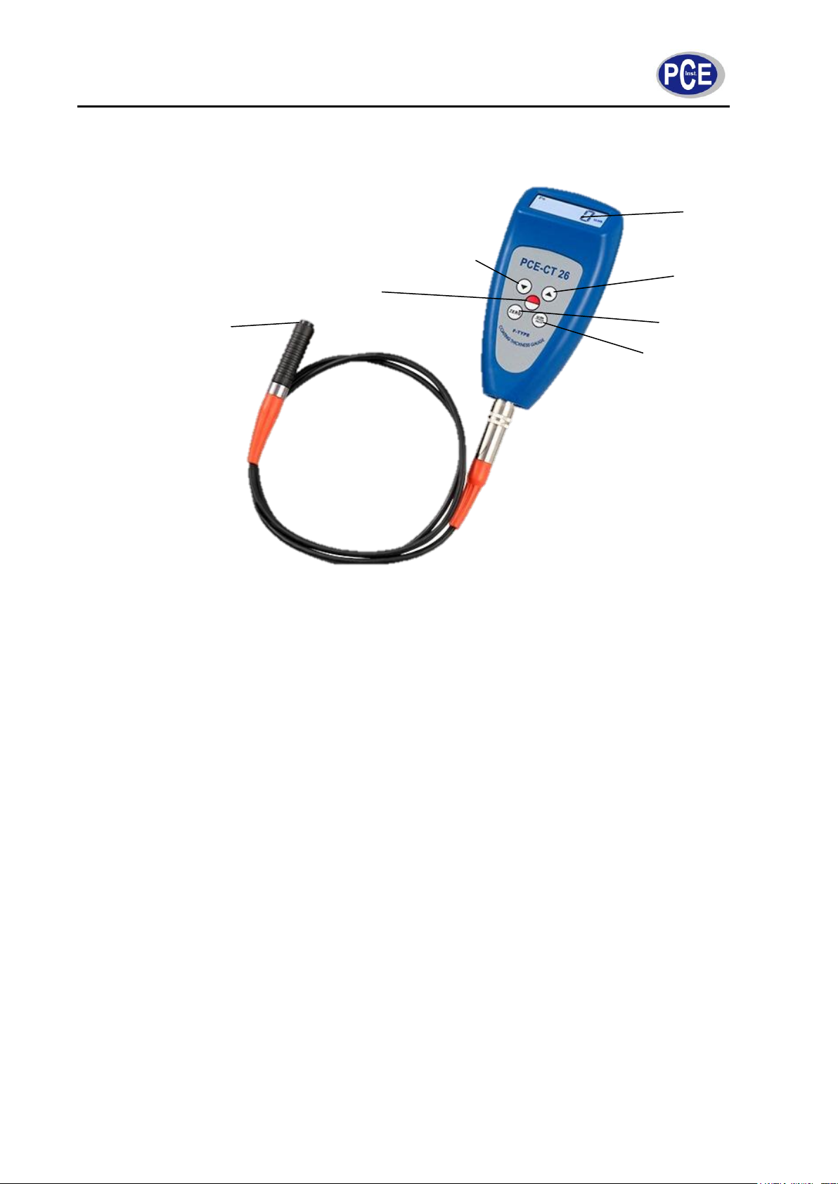
3 Front Panel Descriptions
3-1 3-3
Manual
3-2
3-5
3-4
3-6
3-7
3-1 Probes
3-2 Display
3-3 Zero Key
3-4 Plus Key
3-5 Minus Key
3-6 Power Key (multifunctional)
3-7 µm / mil conversion key
4 Measuring Procedure
1. Plug in the F probe
2. Press the power key to switch in the device and ‘0’ displays on the display. The gauge will restore
the state of last operation itself, with a symbol of ‘Fe’ indicating on the display.
3. Place the probe onto a coating layer to be measured. The reading on the display is the thickness
of the coating layer. The reading can be corrected by pressing the plus key or minus key while
the probe is away from the substrate or the measured body.
4. To take the next measurement, just lift the probe to more than 1 centimetre and then repeat step
3.
5. If suspecting the accuracy of measurement, you should calibrate the gauge before taking the
measurements. For the calibration procedures please refer to the calibration part of the manual.
6. The gauge can be switched off by pressing the power key at any time. On the other side, the
gauge will turn itself off after 50 seconds after the last operation.
7. To change the measurement unit ‘µm’ or ‘mil’ by:
A. Depressing the shortcut key (3-7) OR
B. Depressing the power key and not releasing it until ‘UNIT’ is displayed and then
pressing zero key (~7 seconds).
Page 5

Manual
8. To change measurement mode from the single to continuous or vice visa, just depressing the
power key and not releasing it till ‘SC’ is on the display and then depressing and then pressing
zero key. The Symbol ‘(( ))’ represents continuous mode and ‘S’ represents single mode. It is
about 9 seconds from starting depressing power key.
5 Calibration
1. Place the probe on the iron substrate or an uncoated standard steadily. Press the zero key and
‘0’ will appear on the display before lifting the probe. If the zero key is pressed and the probe
is not placed on the substrate or an uncoated standard, the zero calibration is invalid.
2. Select an appropriate calibration foil according to your measurement range.
3. Place the standard foil selected onto the substrate or the uncoated standard.
4. Place the sensor mildly onto the standard foil and lift. The reading on the display is the value
measured. The displayed reading can be corrected by pressing either the plus- or the minus key
while the probe is away from the substrate or the measured body.
5. Repeat step 4 till the result is correct.
6 Battery Replacement
1. When it is necessary to replace the battery, the gauge will indicate so by displaying a battery
symbol.
2. Slide the battery cover away from the instrument and remove the batteries.
3. Install the new batteries correctly into the case. If the instrument is not to be used for any
extended period, remove the batteries in order to avoid damage.
7 Considerations
1. In order to weaken the influence of the measured material on the accuracy of measurement, it is
recommended that the calibrations should be done on the uncoated material to be measured.
2. Probes will eventually wear. Probe life will depend on the number of measurements taken and
how abrasive the coating is. Replacement of a probe can be fitted by qualified persons only.
8 Restore Factory Settings
8.1 When to restore?
It is recommended to restore factory settings in one of the following cases.
A. The gauge does not measure any more.
B. Measuring accuracy is degraded caused by the abraded probe or by environmental conditions
that have changed greatly.
C. Replacement of a new probe
8.2 How to restore?
You can restore the factory settings easily. Please follow the below to restore the factory settings.
1. Depress power key and not release it until ‘CAL’ appears on the display. (~5 seconds from
starting depressing power key).
2. When ‘F:H’ is displayed, lift the probe for more than 5 centimetres. Then press the zero key and
the gauge returns to measurement state. The factory setting is restored. Remember to restore
factory setting should be done within 6 seconds at every stage or the gauge will quit itself and
restoration is invalid.
Page 6

Manual
9 Notes
1. Settings includes restoring factory setting, unit setting, S/C setting, which should be done within 6
seconds at every stage or the gauge will quit itself and keep its status before.
2. It is strongly recommended that no changes should be made to the value of Ln, which will
seriously affect the accuracy. Its value can be adjusted by professional persons only
under the cases of replacing a new probe or making the gauge more accurate. It is possible
to change the value of Ln by depressing the plus/minus key after displaying the Ln value and
releasing the power key. Store its value and quit by pressing zero key. Generally the larger the
value of Ln, the smaller the reading on a same thickness. A little variation of value of Ln will
cause a great change in reading at high end (e.g. at 500 µm / 20 mil) The rules to adjust the
value of Ln are as follows:
A. Reading at low end can be adjusted to the exact value by the plus or minus key.
B. To enlarge the Ln if readings are low end (e.g. at 51 µm) is ok but reading at high end (e.g. at
432 µm) is too large. On the contrary, to decrease the Ln if reading at low end (e.g. at 51 µm)
is ok but reading at high end (e.g. 432 µm) is too small.
C. Repeat procedures from A to B until the readings on every standard foil are satisfying the
accuracy.
Please contact PCE Instruments if you have any questions concerning our products, service etc.
 Loading...