

Page 1
© PCE Instruments
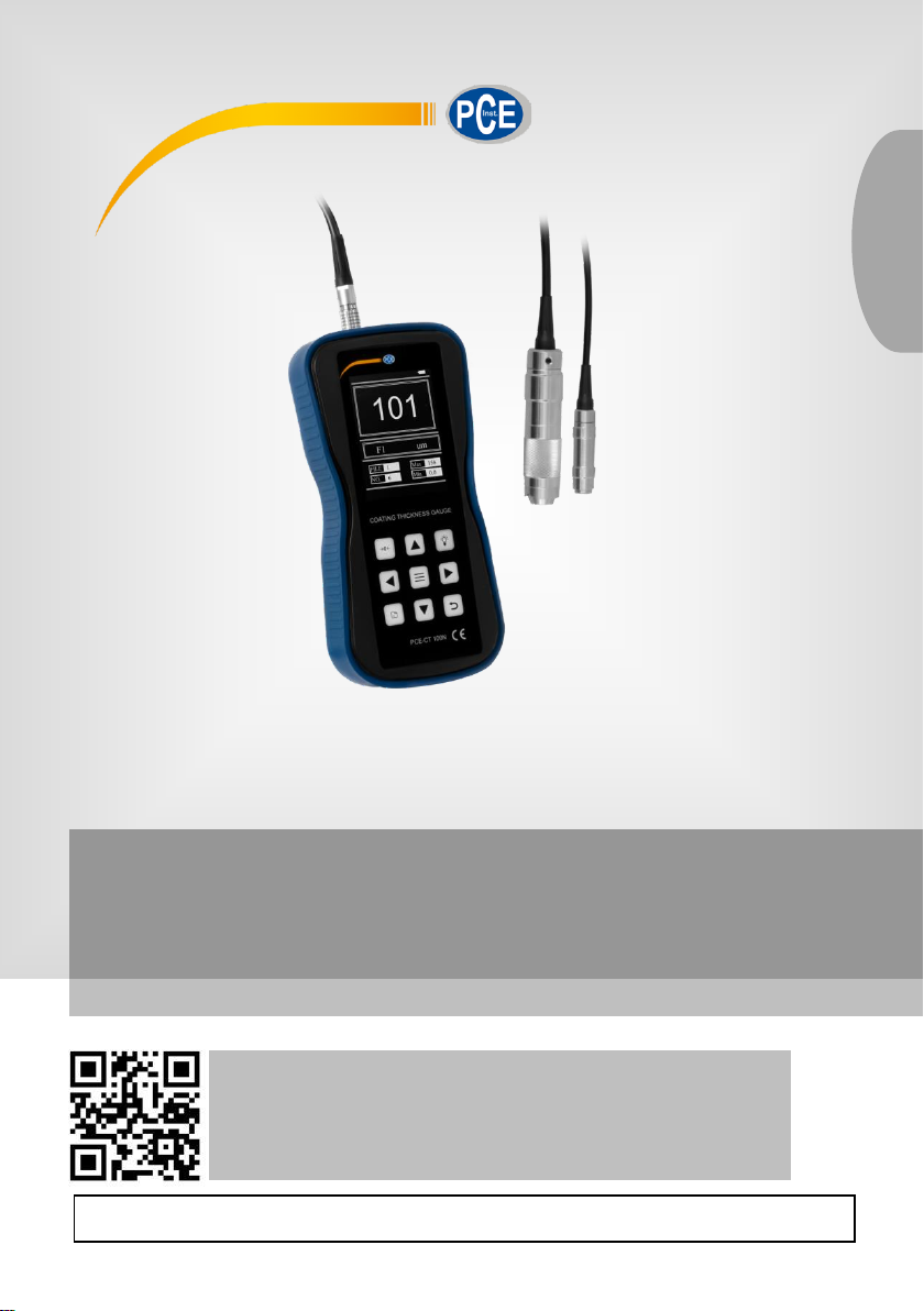
PCE-CT 100N Coating Thickness Gauge
User Manual
User manuals in various languages (français,
italiano, español, português, nederlands, türk, polski,
русский, 中文) can be found by using our
product search on: www.pce-instruments.com
Last change: 5 May 2020
v1.0
English
Page 2

© PCE Instruments
Contents
1 Safety notes ........................................................................................... 1
2 Specifications ........................................................................................ 2
3 Package contents.................................................................................. 2
4 Characteristics ...................................................................................... 2
5 Measuring Principles ............................................................................ 3
6 Device Layout ........................................................................................ 4
7 Screen Layout ....................................................................................... 5
8 Operation Instructions ......................................................................... 5
8.1 Basic measurement steps ................................................................................................ 5
8.2 Measurement process ...................................................................................................... 6
8.3 Measurement setup.......................................................................................................... 7
8.4 Gauge settings ................................................................................................................. 9
8.5 Data processing ..............................................................................................................11
9 Calibration ........................................................................................... 15
10 Maintenance and Repair ..................................................................... 15
10.1 Environmental requirements ............................................................................................15
10.2 Battery replacement ........................................................................................................16
11 Testing Probe Reference .................................................................... 16
11.1 Organic coatings reference table .....................................................................................16
11.2 Non-magnetic metal coatings reference table ..................................................................16
12 Warranty ............................................................................................... 17
13 Disposal ............................................................................................... 17
Page 3

© PCE Instruments
1
1 Safety notes
Please read this manual carefully and completely before you use the device for the first time. The
device may only be used by qualified personnel and repaired by PCE Instruments personnel.
Damage or injuries caused by non-observance of the manual are excluded from our liability and
not covered by our warranty.
• The device must only be used as described in this instruction manual. If used otherwise,
this can cause dangerous situations for the user and damage to the meter.
• The instrument may only be used if the environmental conditions (temperature, relative
humidity, …) are within the ranges stated in the technical specifications. Do not expose
the device to extreme temperatures, direct sunlight, extreme humidity or moisture.
• Do not expose the device to shocks or strong vibrations.
• The case should only be opened by qualified PCE Instruments personnel.
• Never use the instrument when your hands are wet.
• You must not make any technical changes to the device.
• The appliance should only be cleaned with a damp cloth. Use only pH-neutral cleaner,
no abrasives or solvents.
• The device must only be used with accessories from PCE Instruments or equivalent.
• Before each use, inspect the case for visible damage. If any damage is visible, do not
use the device.
• Do not use the instrument in explosive atmospheres.
• The measurement range as stated in the specifications must not be exceeded under
any circumstances.
• Non-observance of the safety notes can cause damage to the device and injuries to
the user.
We do not assume liability for printing errors or any other mistakes in this manual.
We expressly point to our general guarantee terms which can be found in our general terms of
business.
If you have any questions please contact PCE Instruments. The contact details can be found at
the end of this manual.
Page 4

© PCE Instruments
2
2 Specifications
Measurement range
0 ... 1250 µm
Accuracy
±(1 % + 1 µm)
Resolution
0.1 µm (<99.9 µm)
1 µm (>100 µm)
Calibration method
One point/two point
Memory
500 data
Measuring method
Single measurement/continuous measurement
Communication interface
Wi-Fi, USB
Operating conditions
0 ... 50 °C, 20 ... 90 % RH not condensed
Dimensions
170 x 85 x 35 mm
Weight
approx. 335 g (with battery)
3 Package contents
1 x Coating Thickness Gauge PCE-CT 100N
1 x NFe Probe
1 x Fe Probe
1 x USB-Storage
1 x Reference foil set
1 x Aluminium/Iron calibration plate
2 x 1.5 V AA Batteries
1 x User Manual
4 Characteristics
• WIFI function
• Touch screen
• Uses magnetic and eddy current thickness measurement method to measure:
o magnetic metal substrate thickness of non-conductive coating
o thickness of non-magnetic coating layers
o non-magnetic metal substrates
• Two probe types:
o Ferrous (Fe)
o Non-Ferrous (NFe)
• Two measurement modes:
o Continuous measurement mode (CONTINUE)
o Single measurement mode (SINGLE)
o Both methods can be used to calibrate the instrument, while basic calibration
methods can be used to detect system error corrections
• Two operating modes:
o Direct mode (DIRECT)
o Group means (AB)
Page 5

© PCE Instruments
3
• Five statistics:
o Average (MEAN)
o Maximum (MAX)
o Minimum (MIN)
o Number of tests (NO.)
o Standard deviation (S.DEV)
• Storage function:
o 500 measurements for storage
• Delete function:
o Single or multiple entry deletion
• Threshold Setting
o For measured values outside of the gauge’s automatic alarm
• USB Storage:
o measured values can be stored on a USB flash drive in text format
• Beep alerts during operation
• Automatic and manual shutdown
5 Measuring Principles
The gauge uses magnetic and eddy current thickness measurement methods. The nondestructive measurement can measure the thickness of magnetic metals (such as steel, iron,
alloy steel) and hard magnetic and non-magnetic coatings (such as aluminium, chromium, copper,
enamel, rubber, paint, etc.); the thickness of non-conductive coatings (such as enamel paint,
plastic, rubber, etc.) of non-magnetic metals (such as copper, aluminium, zinc, tin, etc.).
Magnetic measurement method:
• When the (Fe) probe comes into contact with a metal surface, the magnetic field will be
amplified. It then generates a voltage in a second coil (measuring coil). This voltage
depends on the distance from the metal surface. If a non-magnetic coating is present,
a defined distance results between the probe and the metal surface, and thus a defined
coil voltage. This is electronically evaluated and digitally displayed as the coating
thickness.
Eddy current measuring method:
• When the (NFe) probe with its alternating field approaches a non-ferrous metal, an
alternating current – called the eddy current – is induced in this metal. This produces
another electro-magnetic alternating field in the opposite direction, weakening the
original field. The effect in the probe is a change of inductiveness. By placing the probe
in contact with the coating, a defined distance between the probe and the non-ferrous
metal results, thus leading to a defined inductivity. This will be electronically evaluated
and digitally displayed as the coating thickness.
Page 6
© PCE Instruments
4
6 Device Layout
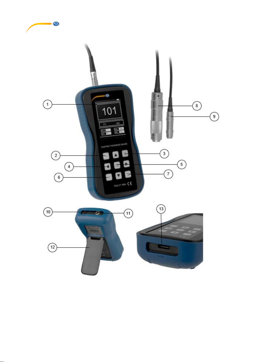
1. Display Screen
8. NFe Probe
2. Zero-In Calibration
9. Fe Probe
3. Backlight
10. On/Off Switch
4. Navigation Keys
11. Probe Input
5. Menu
12. Stand
6. File Browser
13. USB Port
7. Back
Page 7
© PCE Instruments
5
7 Screen Layout
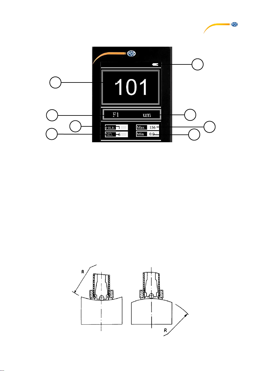
1. Measurement result
5. Battery status
2. Measurement mode
6. Unit of measurement
3. File number
7. Max threshold
4. Measurement count
8. Min threshold
8 Operation Instructions
8.1 Basic measurement steps
8.1.1 Sample piece surface preparation
• The preparation of the sample surface must comply with the relevant requirements in
chapter 11.
• In the process of preparing the sample surface, the temperature on the sample surface
should be avoided as much as possible.
• If the surface to be tested is too rough, it will cause measurement errors. Therefore, the
sample surface must be exposed to metallic luster and be smooth and oil-free.
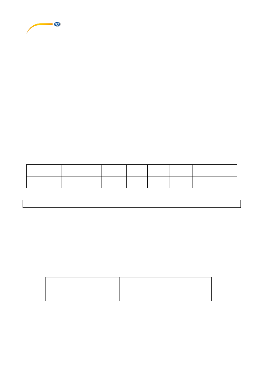
• Surface: A flat test surface is preferable. A sample surface with a radius of curvature of
less than 30 mm must be tested with a small support ring or a profiled support ring.
1 2 3 4 5 6 7
8
Page 8
© PCE Instruments
6
• Sample support
o For heavy sample pieces: no support is required
o For medium sized pieces: the sample must be placed on a flat, stable surface
with no shaking.
• The minimal sample surface thickness must comply with the requirements of Table 3.
• For hard surface layers, the depth of the layer must comply with the requirements of
Table 3.
• Coupling:
o Light samples must be tightly coupled with a strong support. The two coupling
surfaces must be flat and smooth, and the amount of coupling agent should
not be excessive. The test direction must be perpendicular to the coupling
plane.
o If the sample is a large-area plate, long rod, or bent; even if the weight or
thickness are large, the sample piece may be deformed or unstable, this will
result in inaccurate test values. Therefore, the sample should be reinforced
or supported on the back side of the sample piece.
• The sample surface should not exceed 30 Gauss.
8.2 Measurement process
Before measurement, the instrument can be tested with a random test block. The indication error
and repeatability should not exceed the requirements of table 1.
Repeatability
[µm]
1-point
calibration (µ)
±(3 %H +
0.7)
±(3 %H
+ 1)
±(3 %H
+ 10)
±(3 %H
+ 0.7)
±(3 %H
+ 1.5)
±(3 %H
+ 1)
2-point
calibration (m)
±(1 %H +
0.7)
±(1 %H
+ 1)
±(1 %H
+ 10)
±(1 %H
+ 0.7)
±(1 %H
+ 1.5)
-
Table 1
Note: the random test block must be measured with a calibrated device.
8.2.1 Measurement procedure
• Insert the probe into the probe input on the device.
• The probe must be placed into the test sample. The probe, sample and operator must
now remain perfectly stable and the probe should be as perfectly perpendicular to the
sample as possible.
• If the resulting value exceeds the measurable amount, the device will need to be
calibrated separately with 5 test pieces.
• The distance between any two indentations or the distance from the centre of any
indentation must comply with table 2.
Table 2
Distance between two
indentation centres
Indentation centre distance from the
edge of the sample
not less than
not less than
3mm
5mm
Page 9
© PCE Instruments
7
8.3 Measurement setup
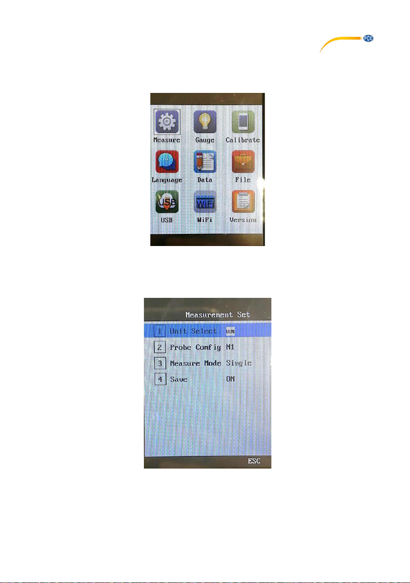
• Press the Menu button to enter the Instrument Menu Settings screen; the screen
displays the nine options for the first level menu.
• Use the ◄ or ► buttons to navigate the menu to the measure icon.
• Press the menu button (≡) to enter the measurement settings.
• Press the back button to end the setup and return to the previous menu.
8.3.1 Unit setup
• Use the ▲ and ▼buttons to navigate the menu to the unit select setting.
• Use the ◄ or ► buttons to change the selected value.
• Press the back button to end the setup and return to the previous menu.
Page 10
© PCE Instruments
8
8.3.2 Probe setup
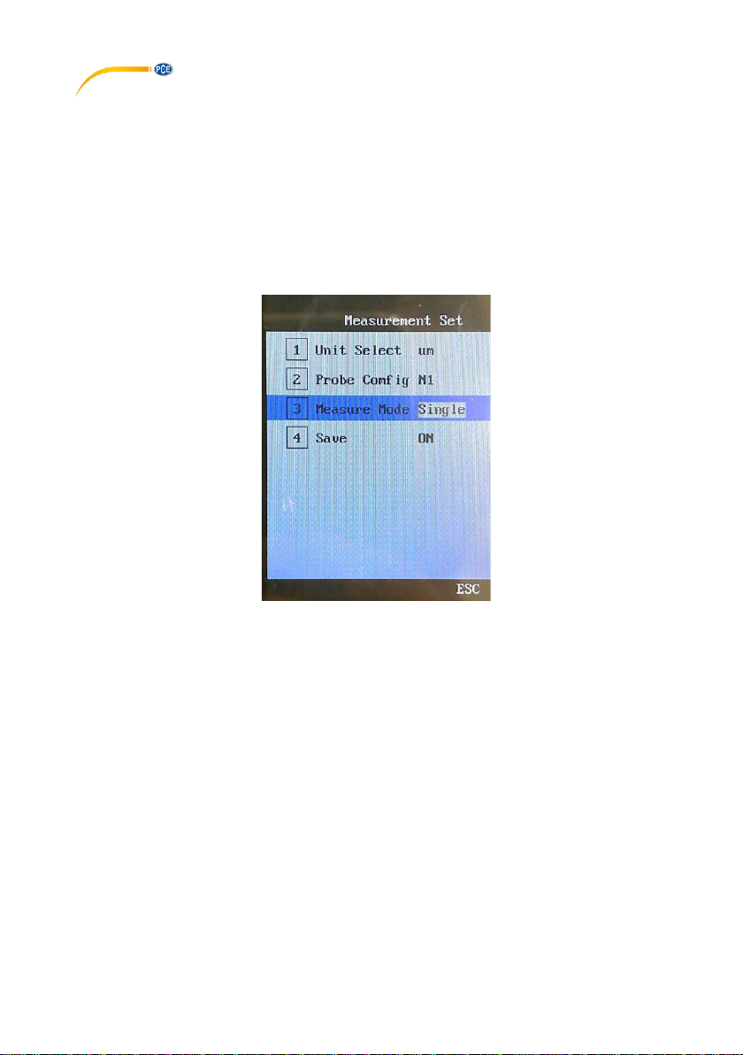
• Use the ▲ and ▼buttons to navigate the menu to the probe configuration.
• Use the ◄ or ► buttons to change the selected value.
• Press the back button to end the setup and return to the previous menu.
• Probe replacement:
o Turn the device off
o Replace the probe
o Turn the device back on. The probe config. setting has now been
automatically changed.
8.3.3 Measurement mode
• Use the ▲ and ▼buttons to navigate the menu to the measurement mode.
• Use the ◄ or ► buttons to change the selected value.
• Press the back button to end the setup and return to the previous menu.
Page 11
© PCE Instruments
9
8.3.4 Automatic storage
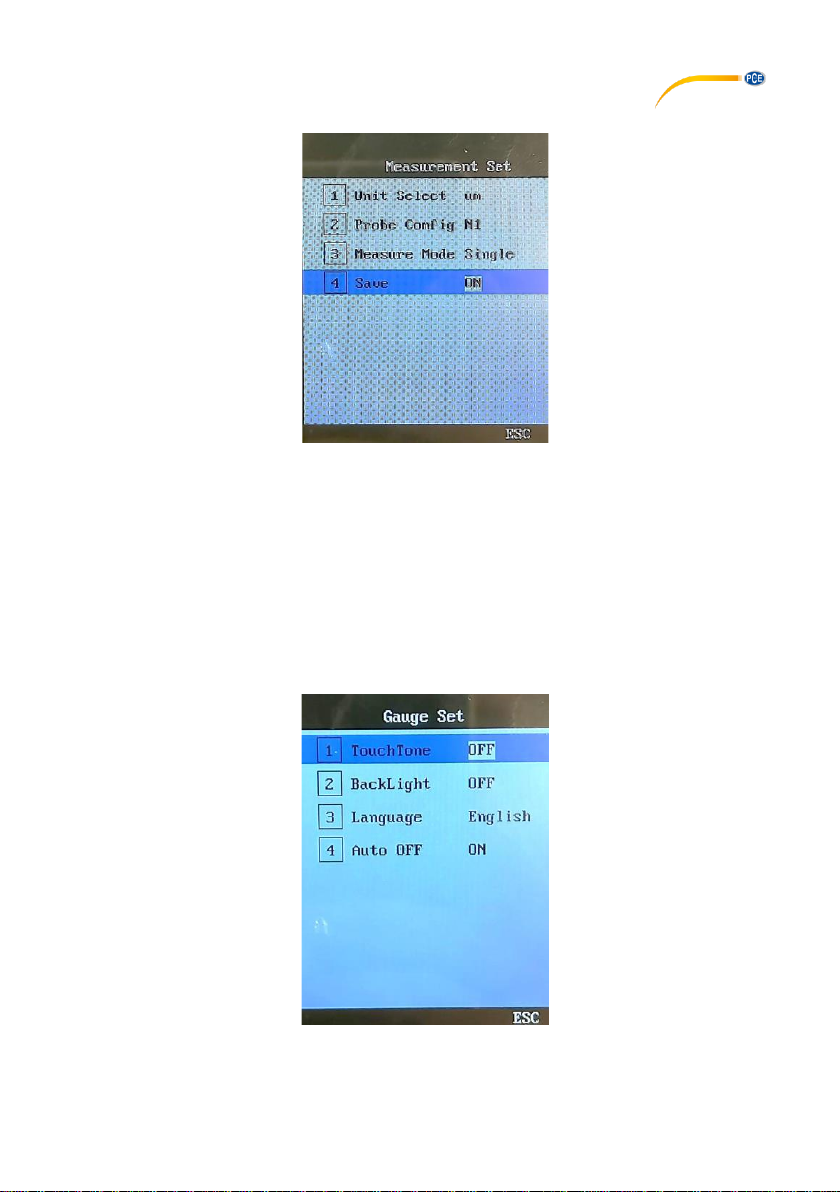
• Use the ▲ and ▼buttons to navigate the menu to the save mode.
• Use the ◄ or ► buttons to change the selected value.
• Press the back button to end the setup and return to the previous menu.
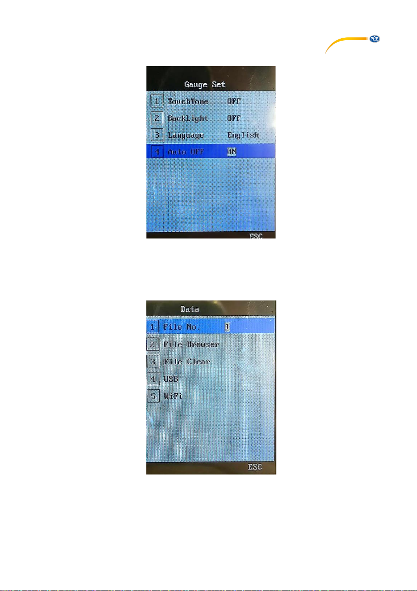
8.4 Gauge settings
• Press the Menu button to enter the Instrument Menu Settings screen.
• Use the ◄ or ► buttons to navigate the menu to the gauge icon.
• Press the menu button (≡) to enter the gauge settings.
• Press the back button to end the setup and return to the previous menu.
8.4.1 Touch tone settings
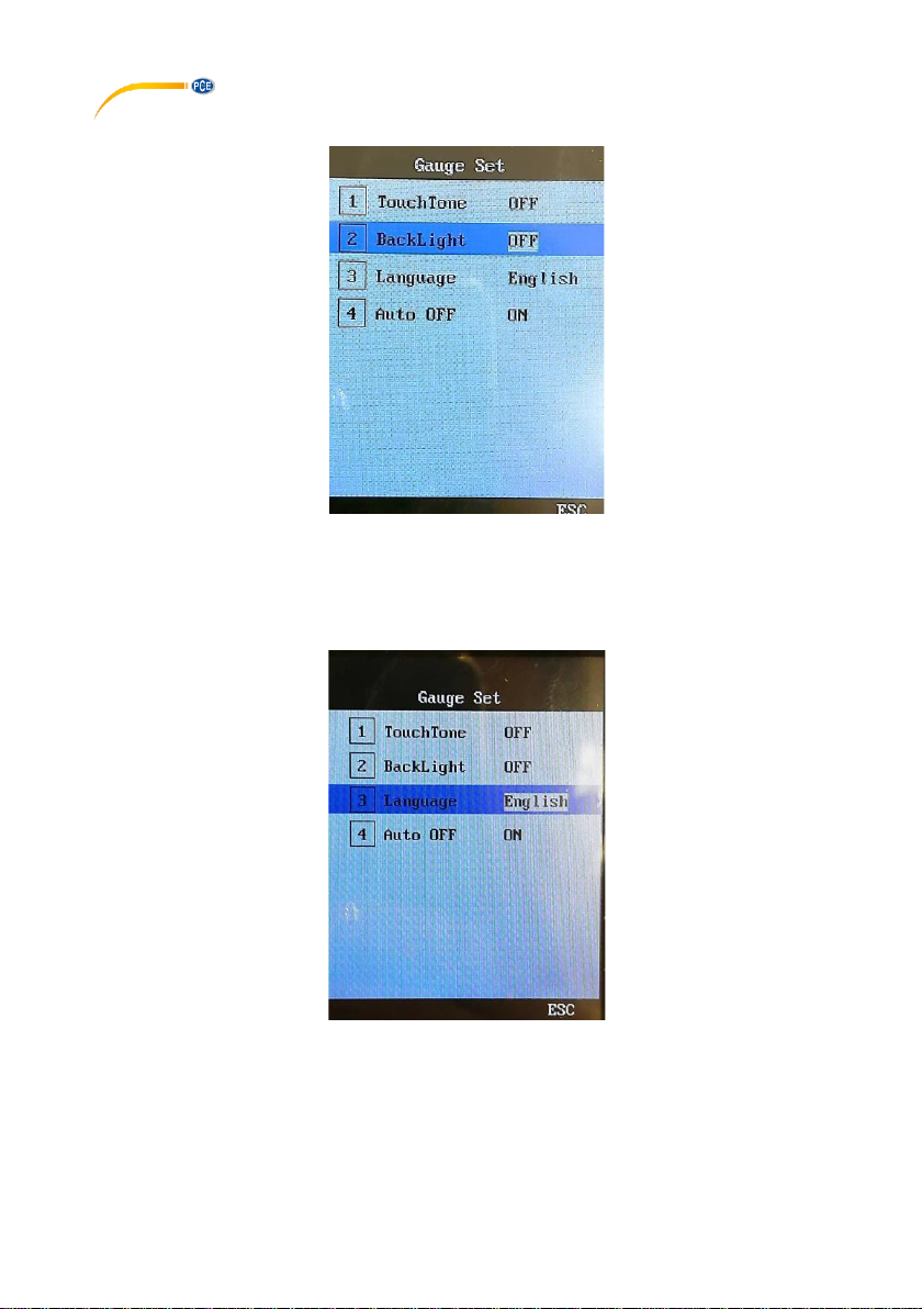
• Use the ▲ and ▼buttons to navigate the menu to the touch tone setting.
• Use the ◄ or ► buttons to change between on and off.
• Press the back button to end the setup and return to the previous menu.
Page 12
© PCE Instruments
10
8.4.2 Backlight settings
• Use the ▲ and ▼buttons to navigate the menu to the backlight setting.
• Use the ◄ or ► buttons to change between on and off.
• Press the back button to end the setup and return to the previous menu.
8.4.3 Language settings
• Use the ▲ and ▼buttons to navigate the menu to the language setting.
• Use the ◄ or ► buttons to change between English and Chinese.
• Press the back button to end the setup and return to the previous menu.
Page 13
© PCE Instruments
11
8.4.4 Auto shut down settings
• Use the ▲ and ▼buttons to navigate the menu to the auto off setting.
• Use the ◄ or ► buttons to change between on and off.
• Press the back button to end the setup and return to the previous menu.
8.5 Data processing
The device has a variety of data processing functions, including on-board storage, browsing, and
deletion of data. The data can be transferred in two ways:
• The internal data can be transferred to a USB drive through the USB interface. This
data can then be transferred from the USB drive onto a computer.
• The data can be transferred over WIFI to another device (mobile/PC).
Page 14
© PCE Instruments
12
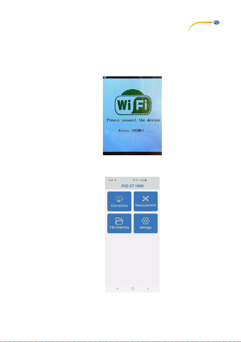
8.5.1 USB memory
The device can directly store data to a USB drive. The USB port can only be used to store data
to a USB drive; it cannot be used to connect the device directly to a PC.
• Press the Menu button to enter the Instrument Menu Settings screen.
• Use the navigational buttons to navigate the menu to the USB icon.
• Press the menu button (≡) to enter the USB settings.
• Insert a USB drive into the USB port and press the menu button (≡) to begin the data
storage process.
• A message box with “Ok!” will be displayed once the process is complete.
• Press the back button to end the setup and return to the previous menu.
• The data can now be read from the USB drive either on a PC or with the file browser
on the device.
Page 15
© PCE Instruments
13
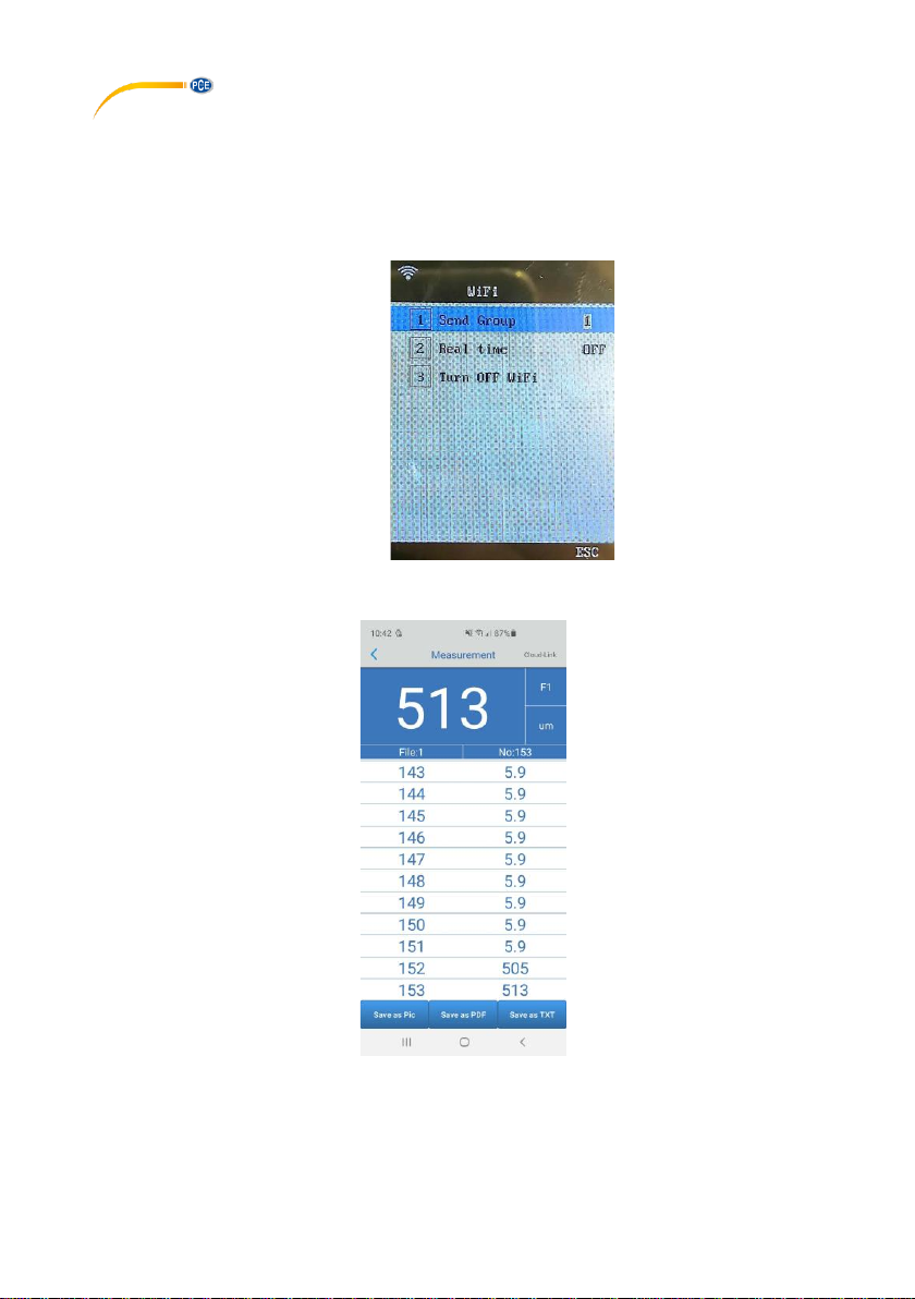
8.5.2 WIFI connection
The device can transfer data over WIFI to another device (mobile/PC).
• Transfer the app from the USB pen drive to your computer.
• Then connect your Android device to your computer and transfer the app file to your
Android device.
• Open the file and install the app.
• Start the WiFi connection on the PCE-CT 100N.
• Connect your Android device to the PCE-CT 100N via WiFi.
• In the Android device, select the option “Measurement” to receive the values.
Page 16
© PCE Instruments
14
• Press the MENU key on the meter. In the menu, you have the following options:
- Send group – here you can select what memory group you would like to transfer
to your Android device
- Real time – send data in real time
- Turn off WiFi
• After selecting one of the two options, the readings will be displayed directly.
• After receiving the values, you can save these as a picture, as .pdf or .txt files.
Page 17
© PCE Instruments
15
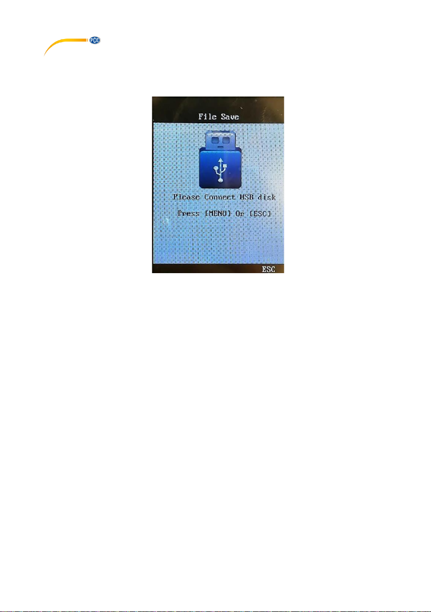
8.5.3 File processing
• Press the Menu button to enter the Instrument Menu Settings screen.
• Use the navigational buttons to navigate the menu to the data icon.
• Press the menu button (≡) to enter the data settings.
• Select the File No. setting and use the ◄ or ► buttons to change the file set number.
The device supports up to 5 file sets.
• Select the File Browser and use the ▼ to ▲ buttons to navigate the 5 file sets. Use the
menu button (≡) to view a file set. Each file set can contain up to 28 data sets.
• Select File Clear and use the menu button (≡) to confirm the process. The entire
selected file set will be cleared.
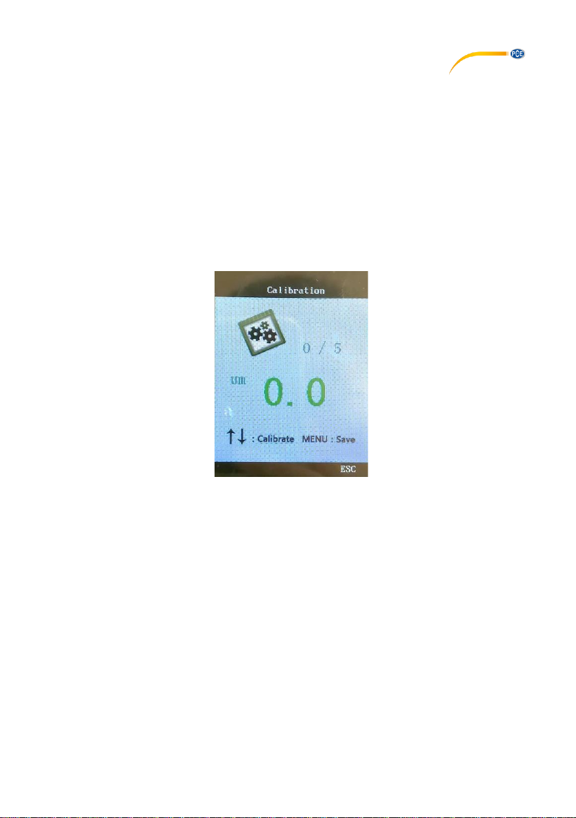
9 Calibration
The device and impact probe must be calibrated with a coating thickness matrix before first use
or after a prolonged period of non-use.
• Press the Menu button to enter the Instrument Menu Settings screen.
• Use the navigational buttons to navigate the menu to the calibrate icon.
• Press the menu button (≡) to enter the data settings.
6 measurements must be performed vertically down into the provided substrate; the first is a zero
calibration (without the substrate).
• Use the ▲ or ▼ buttons to adjust the value to the nominal thickness of the standard
test substrate for each measurement.
• Perform a total of 5 measurements; one test for one test foil.
• Press the menu button (≡) to save and exit the calibration process.
10 Maintenance and Repair
10.1 Environmental requirements
Strictly avoid collisions, heavy dust, moisture, strong magnetic fields, oil stains, and other dirtying
or damaging factors.
Page 18
© PCE Instruments
16
10.2 Battery replacement
The battery life for this is typically 3 years. After the batteries fail, the user can replace them as
follows:
• Switch the device off.
• Unscrew and separate the battery cover on the back of the main unit.
• Replace the drained batteries.
• Replace the cover and tighten the screw.
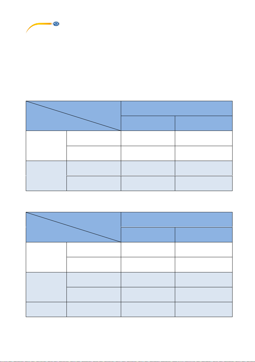
11 Testing Probe Reference
11.1 Organic coatings reference table
Coating
Base
Organic materials and other non-metallic coatings
(such as: paint, enamel, etc.)
Cover thickness <
100µm
Cover thickness > 100µm
Magnetic metal
(Iron, Steel, etc.)
Measuring area > 30mm
F400: 0~400µm
F1: 0~1250µm
F400: 0~400µm
F1: 0~1250µm
F10: 0~10mm
Measuring area < 30mm
F400: 0~400µm
F1: 0~1250µm
F400: 0~400µm
Copper,
Aluminium,
Tin, etc.
Measuring area > 10mm
N400: 0~400µm
N1: 0~1250µm
N400: 0~400µm
N1: 0~10mm
Measuring area < 10mm
N400: 0~400µm
N1: 0~1250µm
N400: 0~400µm
11.2 Non-magnetic metal coatings reference table
Coating
Probe
Non-magnetic metal layer (such as: chromium, zinc,
aluminium, copper, tin, silver, etc.)
Cover thickness <
100µm
Cover thickness > 100µm
Magnetic metal
(Iron, Steel, etc.)
Measuring area > 30mm
F400: 0~400µm
F1: 0~1250µm
F400: 0~400µm
F1: 0~1250µm
F10: 0~10mm
Measuring area < 30mm
F400: 0~400µm
F1: 0~1250µm
F400: 0~400µm
Copper,
Aluminium,
Tin, etc.
Measuring area > 10mm
Only for copper plating
N400: 0~40µm
……….
Measuring area < 10mm
……….
……….
Plastic, nonmetal base
Measuring area > 7mm
Cn02: 10~200µm
Cn02: 10~200µm
Page 19
12 Contact
You can read our Contact terms in our General Business Terms which you can find here:
https://www.pce-instruments.com/english/terms.
13 Disposal
For the disposal of batteries in the EU, the 2006/66/EC directive of the European Parliament
applies. Due to the contained pollutants, batteries must not be disposed of as household waste.
They must be given to collection points designed for that purpose.
In order to comply with the EU directive 2012/19/EU we take our devices back. We either re-use
them or give them to a recycling company which disposes of the devices in line with law.
For countries outside the EU, batteries and devices should be disposed of in accordance with
your local waste regulations.
If you have any questions, please contact PCE Instruments.
© PCE Instruments
17
Page 20

© PCE Instruments
18
PCE Instruments contact information
Germany France Spain
PCE Deutschland GmbH PCE Instruments France EURL PCE Ibérica S.L.
Im Langel 4 23, rue de Strasbourg Calle Mayor, 53
D-59872 Meschede 67250 Soultz-Sous-Forets 02500 Tobarra (Albacete)
Deutschland France España
Tel.: +49 (0) 2903 976 99 0 Téléphone: +33 (0) 972 3537 17 Tel. : +34 967 543 548
Fax: +49 (0) 2903 976 99 29 Numéro de fax: +33 (0) 972 3537 18 Fax: +34 967 543 542
[email protected] [email protected] [email protected]
www.pce-instruments.com/deutsch www.pce-instruments.com/french www.pce-instruments.com/espanol
Germany United Kingdom Italy
PCE Produktions- und PCE Instruments UK Ltd PCE Italia s.r.l.
Entwicklungsgesellschaft mbH Unit 11 Southpoint Business Park Via Pesciatina 878 / B-Interno 6
Im Langel 26 Ensign Way, Southampton 55010 Loc. Gragnano
D-59872 Meschede Hampshire Capannori (Lucca)
Deutschland United Kingdom, SO31 4RF Italia
Tel.: +49 (0) 2903 976 99 471 Tel: +44 (0) 2380 98703 0 Telefono: +39 0583 975 114
Fax: +49 (0) 2903 976 99 9971 Fax: +44 (0) 2380 98703 9 Fax: +39 0583 974 824
[email protected] [email protected] [email protected]
www.pce-instruments.com/deutsch www.pce-instruments.com/english www.pce-instruments.com/italiano
The Netherlands China Hong Kong
PCE Brookhuis B.V. PCE (Beijing) Technology Co., Limited PCE Instruments HK Ltd.
Institutenweg 15 1519 Room, 6 Building Unit J, 21/F., COS Centre
7521 PH Enschede Zhong Ang Times Plaza 56 Tsun Yip Street
Nederland No. 9 Mentougou Road, Tou Gou District Kwun Tong
Telefoon: +31 (0)53 737 01 92 102300 Beijing, China Kowloon, Hong Kong
[email protected] Tel: +86 (10) 8893 9660 Tel: +852-301-84912
www.pce-instruments.com/dutch [email protected] [email protected]
www.pce-instruments.cn www.pce-instruments.cn
United States of America Turkey
PCE Americas Inc. PCE Teknik Cihazları Ltd.Şti.
711 Commerce Way suite 8 Halkalı Merkez Mah.
Jupiter / Palm Beach Pehlivan Sok. No.6/C
33458 FL 34303 Küçükçekmece - İstanbul
USA Türkiye
Tel: +1 (561) 320-9162 Tel: 0212 471 11 47
Fax: +1 (561) 320-9176 Faks: 0212 705 53 93
[email protected] [email protected]
www.pce-instruments.com/us www.pce-instruments.com/turkish
 Loading...