

Page 1

Manual
Cable Fault Meter PCE-CL 20
Version 1.0
Date of creation: 21.06.2016
Date of last change: 21.06.2016
PCE Americas Inc.
711 Commerce Way
Suite 8
Jupiter
FL-33458
USA
From outside US: +1
Tel: (561) 320-9162
Fax: (561) 320-9176
info@pce-americas.com
www.pce-instruments.com/english
www.pce-instruments.com
PCE Instruments UK Ltd.
Units 12/13
Southpoint Business Park
Ensign way
Hampshire / Southampton
United Kingdom, SO31 4RF
From outside UK: +44
Tel: (0) 2380 98703 0
Fax: (0) 2380 98703 9
info@pce-instruments.com
Page 2

Manual
2
Contents
1 Safety notes ............................................................................................................. 3
2 Specification ............................................................................................................ 4
2.1 Technical specifications .............................................................................................................. 4
2.2 Delivery contents ........................................................................................................................ 4
3 System description ................................................................................................. 5
3.1 Receiver unit ............................................................................................................................... 5
3.2 Transmitter unit ........................................................................................................................... 7
4 Getting started ......................................................................................................... 8
4.1 Batteries / Power supply ............................................................................................................. 8
4.2 Measurement method ................................................................................................................. 8
4.3 Optional connections to the cable locator .................................................................................. 9
4.3.1 Single-pole use .............................................................................................................................. 9
4.3.2 Two-pole use .................................................................................................................................. 9
5 Operation ................................................................................................................. 9
5.1 Single-pole use ........................................................................................................................... 9
5.1.1 In open current circuits ................................................................................................................... 9
5.1.2 Locating and tracing of lines and sockets .................................................................................... 10
5.1.3 Locating the cable breaks ............................................................................................................ 11
5.1.4 Detection of cable breaks with the help of two transmitters. ....................................................... 12
5.1.5 Troubleshooting of the underfloor heating ................................................................................... 13
5.1.6 Detection of a blocked part in an installed non-metallic piping .................................................... 14
5.1.7 Finding metallic tap water- and heating pipe ............................................................................... 15
5.1.8 Finding power supply circuits on the same floor .......................................................................... 16
5.1.9 Tracking an underground current circuit ...................................................................................... 17
5.2 Bipolar use ................................................................................................................................ 18
5.2.1 Use in closed current circuits ....................................................................................................... 18
5.2.2 Detection of fuses ........................................................................................................................ 19
5.2.3 Increase of the effective radius when tracking the loaded current circuits .................................. 23
5.2.4 Identification of the mains voltage search of the breaks in the current circuit ............................. 24
5.3 Additional measuring function .................................................................................................. 24
5.3.1 Voltage measurement with the transmitter .................................................................................. 24
5.3.2 Lamp function ............................................................................................................................... 24
5.3.3 Backlight ....................................................................................................................................... 25
5.3.4 Mute ............................................................................................................................................. 25
5.3.5 Automatic shutdown ..................................................................................................................... 25
6 Maintenance .......................................................................................................... 25
6.1 Finding errors / Troubleshooting .............................................................................................. 25
6.2 Fuse .......................................................................................................................................... 25
7 Warranty ................................................................................................................. 26
8 Disposal ................................................................................................................. 26
9 Contact ................................................................................................................... 26
9.1 PCE Instruments UK ................................................................................................................ 26
9.2 PCE Americas .......................................................................................................................... 26
Page 3

Manual
3
Thank you for purchasing a cable locator from PCE Instruments.
1 Safety notes
Please read this manual carefully and completely before you use the device for the first time. The device
may only be used by qualified personnel and repaired by PCE Instruments personnel. There is no
warranty of damages or injuries caused by non-observance of the manual.
This device may only be used in the way specified in this manual. If used otherwise, this may
cause dangerous situations.
Use the device only when the environmental conditions (temperature, air humidity, ...) are within
the limit values range stated in the specifications. Do not expose the device to extreme
temperatures, direct sunlight, extreme air humidity or moisture.
The case should only be opened by qualified personnel of PCE Instruments.
Do not touch the instrument with wet hands.
You should not make any technical changes to the device.
The appliance should only be cleaned with a damp cloth. Do not use any solvent-based cleaners
or abrasives.
The device must only be used with original PCE accessories or equivalent.
Before each use, please inspect the case for damage. In case of any visible damage, please do
not use the device.
Do not expose the instrument to explosive atmospheres.
The limits for the measured parameters given in the specifications may not be exceeded under
any circumstances.
Do not expose the device to the extreme temperatures or direct sunlight, dust, strong
electromagnetic radiation, splash water, high humidity or condensation, corrosive or explosive
gases or mechanical vibration.
Before the device is used on the current-carrying components, the corresponding isolation
preparations must be met.
Never attempt to make contact between the two poles of the battery elements, for example, via a
cable connection.
Should the instructions be ignored and not followed, it may lead to the damage of the device and
injury of the operator.
This manual is published by PCE Instruments without any guarantee.
We expressly point to our general guarantee terms which can be found in our general terms of business.
If you have any questions, please contact PCE Instruments.
Safety symbols
Symbol
Description
Warning: electrical voltage
Non-observance can cause electric shock.
Page 4

Manual
4
2 Specification
2.1 Technical specifications
Transmitting unit
Output signal
125 kHz
External voltage identification range
DC 12 ... 400 V ±2,5 %
AC 12 ... 400 V (50 ... 60 Hz) ±2,5 %
Display
LCD
Maximum voltage
Max. 400 V AC/DC
Overvoltage category
CAT III 300 V
Pollution degree
2
Power supply
9 V battery
Power consumption (minimum voltage)
Approx.. 31 mA
Power consumption (maximum voltage)
Approx.. 115 mA
Fuse
F 0.5 A 500 V, 6.3 x 32 mm
Operating conditions
0 … +40 °C, <80 % RH
Storage conditions
-20 … +60 °C, <80 % RH
Dimensions
190 x 89 x 42.5 mm
Weight
Approx. 420 g (incl. battery)
Receiver
Detection depth
Depends on material and particular application
Single-pole application
Approx. 0 … 2 m
Two-pole application
Approx. 0 … 0.5 m
Single loop line
Up to 2.5 m
Grid voltage detection
Approx. 0 … 0.4 m
Display
LCD
Power supply
6 x 1.5 V AAA batteries
Power consumption (minimum voltage)
Approx. 32 mA
Power consumption (maximum voltage)
Approx. 89 mA
Operating conditions
0 … +40 °C, <80 % RH
Storage conditions
-20 … +60 °C, <80 % RH
Dimensions
241.5 x 78 x 38.5 mm
Weight
Approx. 350 g (incl. batteries)
2.2 Delivery contents
1 x cable locator PCE-CL 20 (1 x transmitter and 1 x receiver unit)
2 x alligator clips
2 x measuring tips
2 x test leads
1 x grounding rod
1 x carrying strap
1 x carrying bag
1 x 9 V battery
6 x 1.5 V AAA batteries
1 x user manual
Page 5

Manual
5
3 System description
3.1 Receiver unit
1. Lamp
2. Measuring sensor
3. LCD
4. POWER button
5. Backlight / mute
6. Lamp on / off
7. UAC button
8. Manual / automatic measurement
9. Decrease sensitivity (manual measurement)
10. Increase sensitivity (manual measurement)
11. Speaker
Receiver display description
1. Battery voltage receiver
2. Battery voltage transmitter
3. Received transmitting power
4. Symbol for the manual measuring mode
5. Symbol for the automatic measuring mode
6. Automatic measuring mode: signal intensity
Manual measuring mode: display of “SEL”
UAC mode: display of “UAC”
7. Sensitivity (more circles = higher sensitivity)
8. Receive code
9. Signal intensity
10. Mains voltage symbol
11. Mute symbol
Page 6
Manual
6
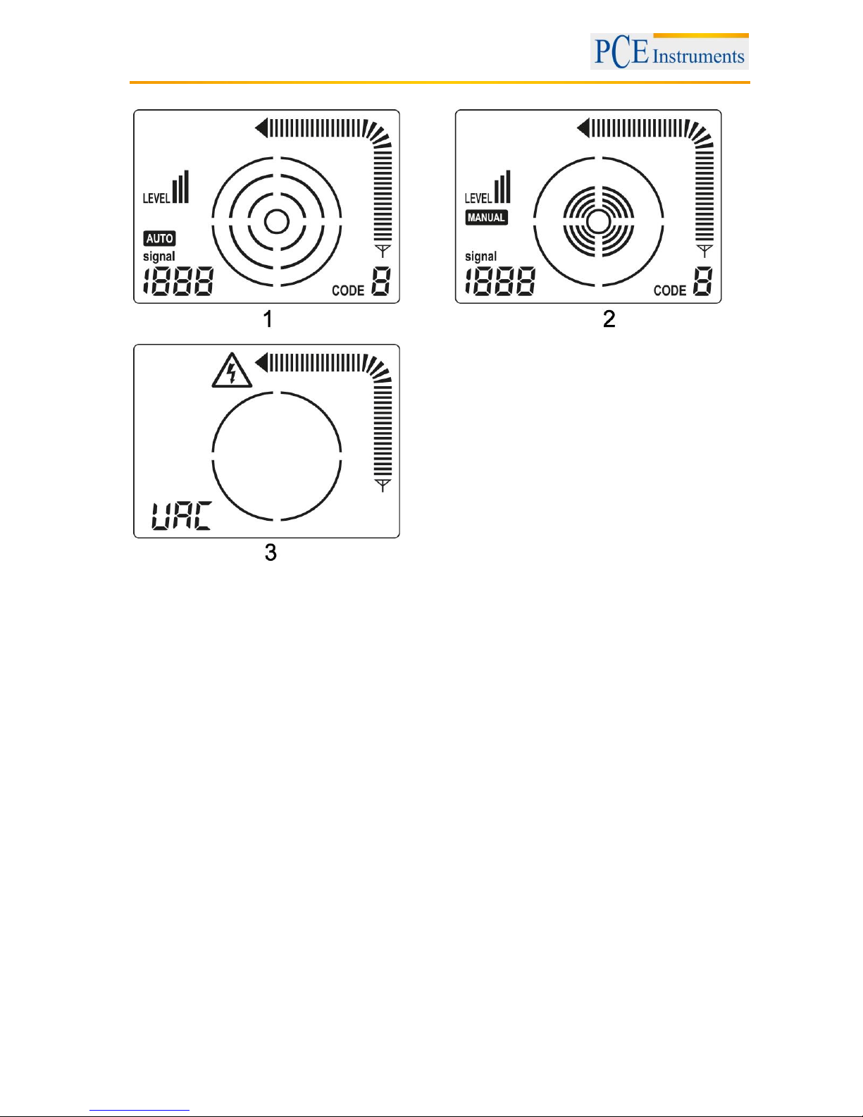
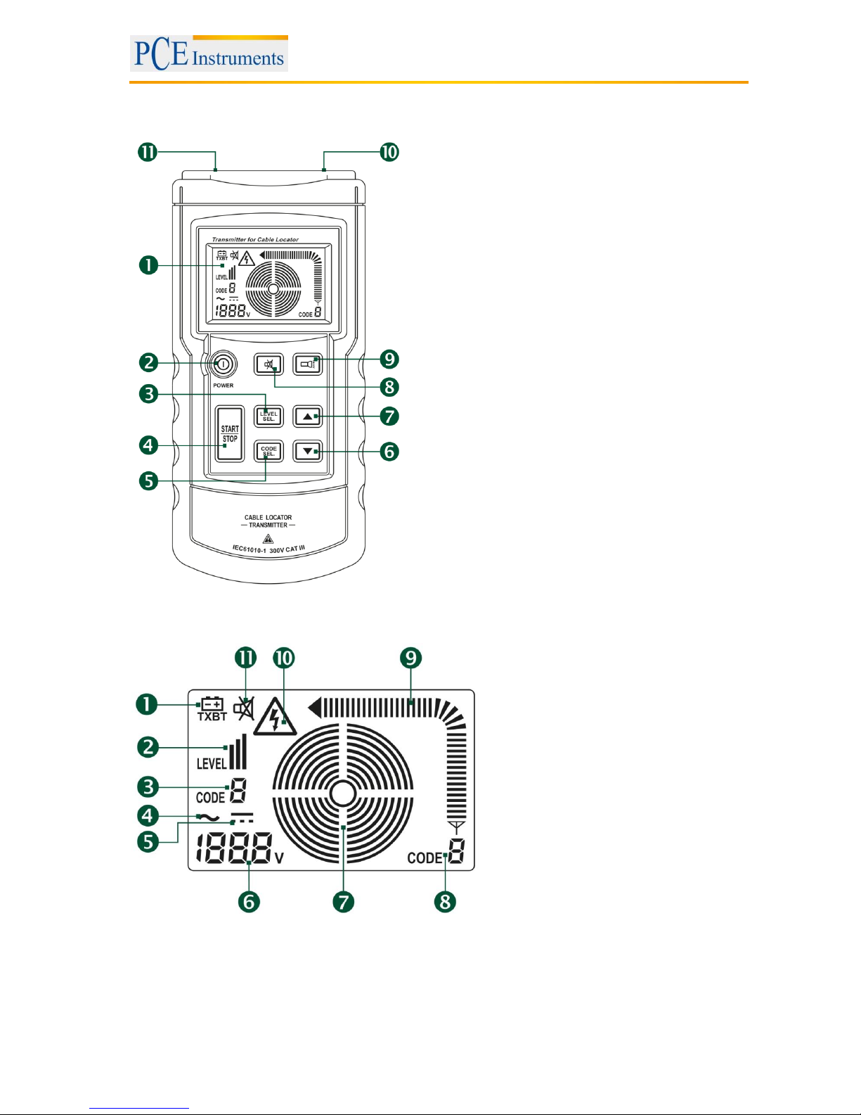
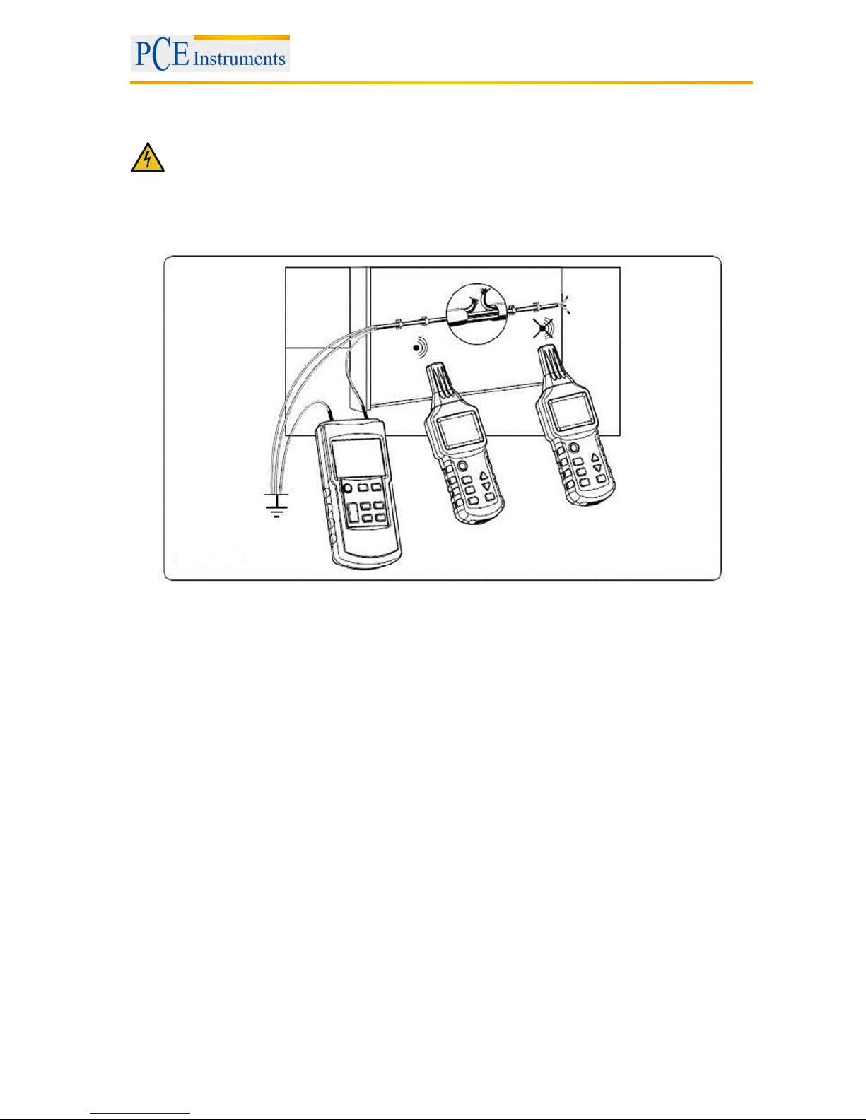
Receiver display in cable search mode
1. Automatic measuring mode
2. Manual measuring mode
3. UAC measuring mode (mains voltage identification)
Page 7
Manual
7
3.2 Transmitter unit
1. LCD
2. POWER-button
3. Set / confirm the transmission power
4. Start / Stop the transmission of the code
information
5. Set / confirm the code information
6. DOWN – button
7. UP – button
8. Mute button
9. lamp on / off
10. input / output opening
11. grounding hole
Transmitter display description
1. Transmitter battery voltage
2. Transmission power
3. Transmission code
4. Mains AC voltage
5. Mains DC voltage
6. Mains voltage value
7. Transmitting status
8. Transmitted code
9. Signal intensity
10. Mains voltage indication
11. Mute indication
Page 8

Manual
8
4 Getting started
4.1 Batteries / Power supply
To insert the batteries, you need a screwdriver. First, the base must be opened, before you can open the
battery compartment of the transmitter. Loosen the fastening screw and remove the cover of the battery
compartment. After that, the battery can be inserted. The receiver unit also has a battery cover, which is
secured with a screw. After the screw is loosened, the battery cover can be removed and the batteries
can be inserted. Once the batteries are inserted, the respective covers must be put back in place and
secured by the screws.
Mind the correct polarity of the batteries when replacing them. If the polarity is not correct this might
damage the device. Also, mind the common guidelines for handling batteries to prevent damage or
injuries. Only use such batteries, as defined in the specifications of this manual. If the unit is not used for
a longer period of time the batteries should be removed to prevent battery leakage.
When the low battery indication flashes on the display, the batteries must be replaced. The device also
gives out an acoustic signal when the battery voltage is low. Please make sure that the device is turned
off and all the test leads are disconnected from the device when replacing the batteries.
4.2 Measurement method
The Cable Locator PCE-CL 20 is a two-part instrument, consisting of a transmitter and a receiver unit.
Additionally, it comes with a variety of measuring accessories.
When locating a cable, the transmitter applies an AC voltage (modulated by digital signals) to the cable or
metal tube to be found, which generates an alternating electric field. When the receiver is held near the
cable or pipe, the electrical field generates a voltage . The receiver can amplify the signal by hundreds of
times. By detecting changes in the signal while moving the receiver, it can detect the position of the cable
or pipe. The cable locator can only detect cables and pipes which are connected to the transmitter
properly. For each application, the connections of the transmitter must ensure a closed circuit.
Page 9

Manual
9
4.3 Optional connections to the cable locator
4.3.1 Single-pole use
The transmitter is connected to only one conductor. Due to the high frequency signal generated by the
transmitter, only one conductor can be located and tracked. The second conductor is the ground. This
arrangement produces a high-frequency current which flows through the conductor and is transmitted to
the ground, similar to a radio or receiver.
4.3.2 Two-pole use
The transmitter is connected to a conductor with two test leads. This method can be used with both
current-carrying and voltage-free cables.
Current-carrying cables
Connect the "+" opening of the transmitter to the phase of the mains cable and the ground opening of the
transmitter to the neutral conductor of the mains cable. In this case, if the mains cable is not loaded, the
modulated current goes from the transmitter via coupling through the distributed capacitance in the mains
cable to the neutral cable and then returns to the transmitter.
Voltage-free cables
Connect the positive output of the transmitter with a mains cable. Connect the ground output with another
parallel mains cable. After that, the modulated current returns directly through the mains cable to the
transmitter. Optionally, both test leads of the transmitter can be connected both ends of a conductor.
Also, the positive output of the transmitter can be attached to the connector of the mains cable, if the
grounding output of the transmitter can be connected to the protective grounding connector of the mains
cable.
5 Operation
5.1 Single-pole use
5.1.1 In open current circuits
- Detecting and locating cable breaks in walls and floors
- Locating and tracing cables, sockets, junction boxes, switches, etc.
- Locating bottlenecks, kinking, buckling and obstructions in pipes with the help of a metal wire
Make sure that the protective ground cable is working properly.
The use in the open circuit is suited for finding current-free sockets and switches.
The tracking depth depends on the medium and application. Typically, it is between 0 and 2 m. The
protective connection of the socket can be used as a ground connection for the transmitter.
Page 10

Manual
10
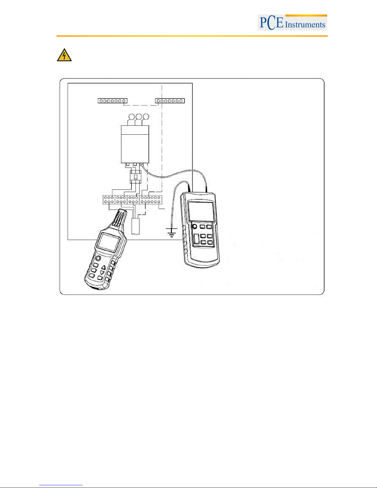
5.1.2 Locating and tracing of lines and sockets
ATTENTION:
- The circuit must not be live.
- The neutral cable and the protective grounding cable must be connected and fully functional.
- Connect the transmitter to the phase cable and the protective grounding cable as shown in the
picture below:
In case of a single-pole application the lateral circuit branches can be tracked (the fuse must be removed
in this example).
If the power cable that is supplied with the signals from the transmitter is located, for example, directly
parallel to the other conductors (e.g. cable slot or channel) or if these conductors are crossed, the signals
are also sent to the other conductors.
During the search and tracing, the closer the locator gets to the cables to be tracked, the stronger the
signal is displayed.
Set the transmission power in order to adapt it to different search radii.
The target position can be located accurately by using the manual mode and adjusting the sensitivity.
Page 11
Manual
11
5.1.3 Locating the cable breaks
ATTENTION:
- The circuit must not be live.
- The cables that are not used, must be connected to the auxiliary ground (as seen in the figure
below).
- Connect the transmitter to the cable connection and to the auxiliary ground.
The transition resistance of a cable break must be higher than 100 kΩ.
Note during the tracking of cable breaks in multicore cables, that all the remaining wires in the shielded
cable or conductor must be grounded properly. This is required to avoid cross coupling of the supplied
signals (through a capacitive effect on the output terminals). The tracking depth for shielded cables and
conductors is different, as the individual wires in the shielded are looped around each other.
The ground connected to the transmitter can be an auxiliary ground, the ground of a grounded socket or a
properly grounded water pipe.
During the tracing of the cable, an abrupt drop of an incoming signal at the receiver takes place at the
point of interruption.
Set the transmission power in order to adapt it to different search radii.
The target position can be located accurately by using the manual mode and adjusting the sensitivity.
Page 12

Manual
12
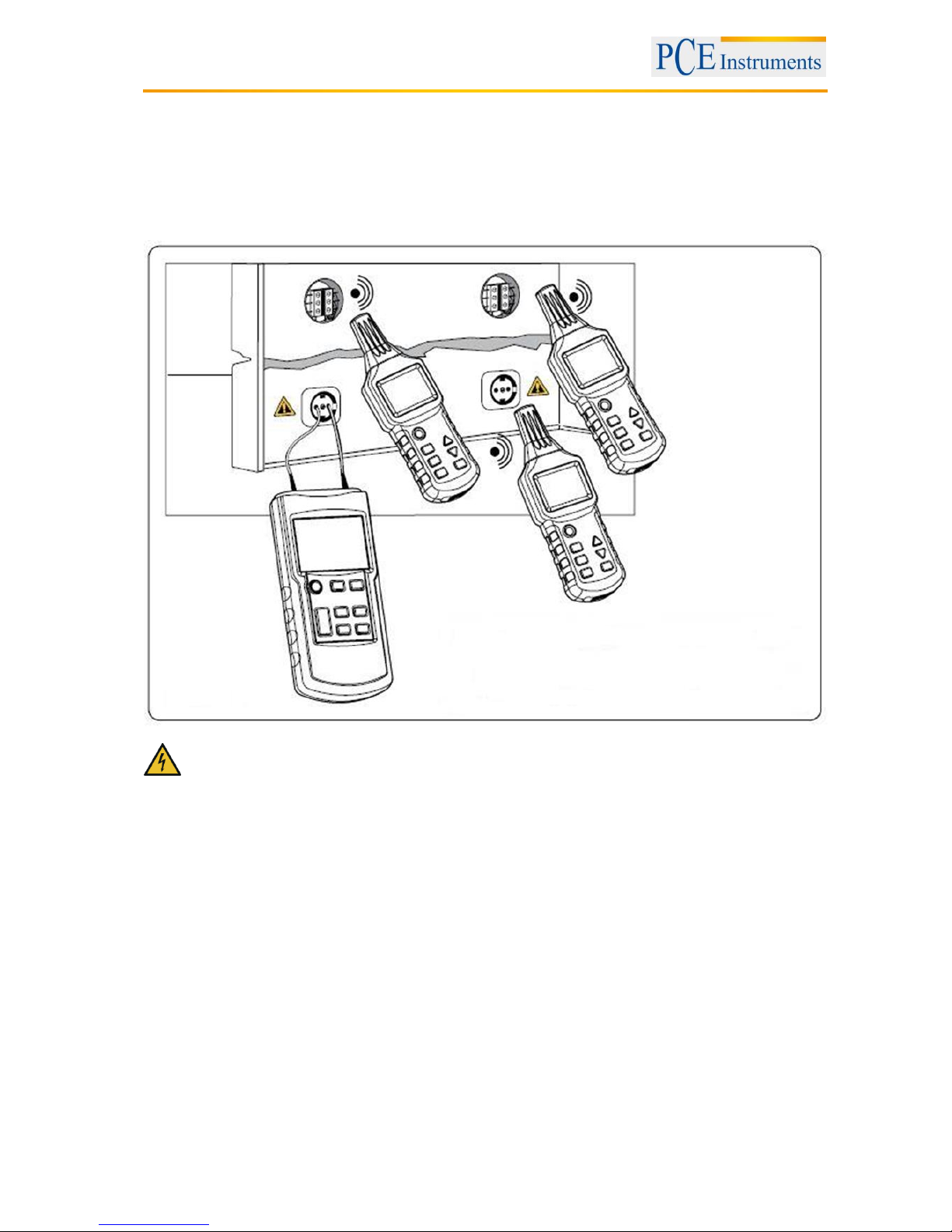
5.1.4 Detection of cable breaks with the help of two transmitters.
In the process of searching for a cable break with a transmitter, which is powered from the end of the
cable, the breaks cannot be tracked accurately when bad conditions prevail due to a field disturbance.
The impairments described above can be easily avoided if two transmitters (one on each end) are used to
detect the cable interruption. In this case, each transmitter is set to a different cable code, e.g.
Transmitter 1 to code F and Transmitter 2 to code C. (A second transmitter with a different cable code is
not included in the delivery and must be ordered separately.)
ATTENTION:
- The circuit must not be live.
- All unused cables must be connected to the auxiliary ground as shown in the following figure.
- Connect both transmitters according to the figure.
When the transmitters are connected in accordance with the figure, the receiver indicates “C“ on the right
side of the cable break. If the receiver goes to the left over the break point, it shows “F”. If you are directly
at the break point no cable code will be displayed because of the overlap of both transmitter signals.
- Set the transmission power in order to adapt it to different search radii.
- The target position can be located accurately by using the manual mode and adjusting the
sensitivity.
- The transition resistance of a cable interruption must be higher than 100 kΩ.
- The ground connected to the transmitter can be an auxiliary ground, the ground of a grounded
socket or a properly grounded water pipe.
- Note when tracking the cable breaks in multicore cables, that all remaining wires in the shielded
cable or conductor must be grounded properly. This is required to avoid the cross coupling of the
supplied signals (through a capacitive effect on the output terminals). The tracking depth for
shielded cables and conductors is different, as the individual wires in the shielded cables are
looped around each other.
Page 13

Manual
13
5.1.5 Troubleshooting of the underfloor heating
ATTENTION:
- The circuit must not be live.
- All unused cables must be connected to the auxiliary ground as shown in the following figure.
- Connect both transmitters in accordance with the figures.
- If a shielding mat is located above the heating wires, there may be no ground connection. If
necessary, disconnect the shield from the ground connection.
- It is necessary to ensure a full grounding, and there should be a sufficient distance between the
ground terminal of the transmitter and the target cable. If this distance is too small, the signal and
the line cannot be detected accurately.
- During tracing the line an abrupt drop of the incoming signal at the receiver marks the point of
interruption.
Page 14

Manual
14
- Set the transmission power in order to adapt it to different search radii.
- The target position can be located accurately by using the manual mode and adjusting the
sensitivity.
5.1.6 Detection of a blocked part in an installed non-metallic piping
ATTENTION:
- The pipe must be made of non-conductive materials (such as plastic).
- The pipe must be drained.
- The transmitter is connected to a metallic conductor (metallic pipe or flexible protective tube) and
an auxiliary grounding cable as shown in the following figure.
- If there is power in the pipeline, turn the power off and perform a proper grounding, when the
pipeline is drained.
- The end of the ground cable must be grounded properly, and there should be a sufficient
distance between the grounding end of the transmitter and the pipeline to be measured. If the
said distance is too small, the signal and the circuit cannot be located accurately.
- If you only have a tube, which is made of non-conductive material (such as, fiberglass for
example), we recommend to install a metal wire with a diameter of about 1.5 mm into the nonconductive tube and then push it into the narrow part.
- The stronger the signals are displayed on the display of the locator during the tracking of the
pipeline, the closer the tracked pipeline is to the locator.
- If the incoming signals at the receiver suddenly become weaker in the course of searching along
the pipeline, blocked spot is located.
- Set the transmission power in order to adapt it to different search radii.
- The target position can be located accurately by using the manual mode and adjusting the
sensitivity.
Page 15
Manual
15
5.1.7 Finding metallic tap water- and heating pipe
ATTENTION:
- The pipeline must be made of metallic materials (for example, piping made of galvanized steel).
- The pipeline must not be grounded. There should be a relatively high resistance between pipe
and floor (otherwise the search distance is very small).
- Use a connection cable to connect the grounding socket on the transmitter with the ground and
ground the end of the grounding cable properly.
- Use a connection lead to connect the socket "+" on the transmitter to the pipeline.
The tracing of the installed tap water pipe and the heating pipe is shown in the following figures
- The end of the grounding cable of the transmitter should be located at a certain distance to the
tracked pipeline. If the distance is too short, the signals and the circuit cannot be accurately
located.
- The stronger the signals are displayed on the display of the locator during the tracking of the
pipeline, the closer the tracked pipeline is to the locator.
- Set the transmission power in order to adapt it to different search radii.
- The target position can be located accurately by using the manual mode and adjusting the
sensitivity.
Page 16
Manual
16
5.1.8 Finding power supply circuits on the same floor
ATTENTION:
Turn off the power in the entire building before measuring.
- The end of the grounding cable of the transmitter must be grounded properly and should be
located at a certain distance from the tracked pipeline. If the distance is too small, the signals and
the current circuit cannot be accurately located.
- The stronger the signals are displayed on the Display of the locator during the tracking of the
pipeline, the closer the tracked pipeline is to the locator.
- Set the transmission power in order to adapt it to different search radii.
- The target position can be located accurately by using the manual mode and adjusting the
sensitivity.
Page 17

Manual
17
5.1.9 Tracking an underground current circuit
ATTENTION:
- The power circuit most not be charged.
- Connect the transmitter as shown in the figure.
- The end of the grounding cable of the transmitter must be grounded properly.
- Select the automatic mode on the receiver.
- Use the displayed signal strength to search and trace the current circuit.
- The distance between the grounding cable and the searches circuit must be as big as possible. If
the distance is too small, the signals and the current circuit cannot be accurately located.
- The search depth is highly dependent on the ground (floor, soil) conditions. Select appropriate
reception sensitivities to locate the circuit accurately.
- If you move the receiver slowly along the searched current circuit, you will find that the display
often changes. The strongest signals indicate the exact place of the current circuit.
- The bigger the distance between the supply signals (transmitter) and the receiver, the lower the
signal strength and weaker the search will be.
Page 18
Manual
18
5.2 Bipolar use
5.2.1 Use in closed current circuits
This method can be used in charged and uncharged circuits:
In uncharged circuits, the transmitter only sends the encoding signals to the circuit.
In charged circuits, the transmitter sends the encoding signals to the circuit, measures and also shows
the voltage of the charged circuit, as can be seen in the following figure:
ATTENTION: Please follow the safety instructions when connecting the loaded circuits to the
transmitter.
- The dielectric strength of the transmitter is 400 V AC / DC.
- The use in closed circuits is suitable for searching sockets, switches, fuses etc. in electrical
installations of charged and uncharged floors.
- The search depth depends on the medium of the ran cable and its use. It is normally less than
0.5 m.
- Set the transmission power in order to adapt it to different search radii.
Page 19

Manual
19
5.2.2 Detection of fuses
In a building with several apartments you use the terminals L and N in the socket of any apartment to
provide the flow of the signals from the transmitter, and set the power of the transmitter at an appropriate
level.
Preparation:
- Turn off all air switches in the distribution box.
- Connect the transmitter according to the following figure.
- The identification and positioning of fuses strongly depends on the wiring situation in the distribution
box. To carry out the search of fuses as precisely as possible, the cover of the distribution box should be
opened or removed and the supply cable of the fuse searched.
- During the search process the fuse with the strongest and most stable signals is the one that is
searched. Due to signal coupling the locator can also detect the signals from other fuses, but the strength
of these signals is usually relatively weak.
- When searching, it is better to insert the sensor of the locator in the inlet of the fuse box in order to
achieve the best search result.
- Set the power of the transmitter in order to adjust it to different search radii. Select the manual mode on
the receiver and the appropriate reception sensitivity to locate the current circuit accurately.
Page 20

Manual
20
5.2.2.1 Searching for a short circuit in the current circuit
Preparation:
- The circuit must be unloaded.
- Connect the transmitter according to the following figure.
- If there is current in the cable, first turn the power off to make the cable unpowered.
- When searching for short circuits in the coated electric wires and cables the search depths vary,
because the core wires in the jacket are twisted with each other. According to our experience only the
short circuits with an impedance less than 20 Ω can be tracked correctly. The impedance of the short
circuit can be measured with a multimeter.
- If the impedance of the short circuit is higher than 20 Ω, try to apply the method of searching for the
breaks in current circuits to locate the short circuit. Use of a relatively strong current for that in order to
connect the defective part (low Ω-connection) or to interrupt it.
- If the incoming signals at the receiver suddenly become weaker in the course of searching along the
pipeline, the place, where a short circuit is located, is found.
- Set the power of the transmitter in order to adjust it to different search radii.
- Select the manual mode on the receiver and the appropriate reception sensitivity to locate the circuit
accurately.
Page 21

Manual
21
5.2.2.2 Finding low-lying current circuits
For bipolar use the search depth is strictly limited if the loop / ring cable consists of core wires in cables
with multiple core wires (such as, for example, NYM 3 x 1.5 mm²), because a short distance between the
supply cable and the loop cable causes a strongly distorted magnetic field. A sufficiently strong magnetic
field cannot be established in the narrow places. If a separate loop cable is used, this problem could be
resolved easily, since a separate conductor could spread the magnetic field much more. In case of the
loop cable it may go about some type of conductive wires or cable rolls. It is important that the distance
between the supply cable and the loop cable is bigger than the depth of laying. In practice, this distance is
usually 2 m or more.
preparations:
- The circuit must be unloaded.
- Connect the transmitter as in the following figure.
- The distance between the supply cable and the loop cable must be at least 2 ~ 2.5 m.
- For this type of application the influence of moisture or mortar on the wall up to the search depth is not
important.
- The stronger the signals displayed on the Nixie Tube of the locator during the tracking of the current
circuit is, the closer to the locator the tracked cable is.
- Set the power of the transmitter in order to adjust it to different search radii.
- Select the manual mode on the receiver and the appropriate reception sensitivity to locate the current
circuit accurately.
Page 22

Manual
22
5.2.2.3 Classify or define the laid current circuit
Preparation:
- The circuit must be unloaded.
- The ends of the core wires must be twisted with each other and conduct all together.
- Connect the transmitter as in the following figure.
- If there is current in the cable, first turn off the power to make the cable unpowered.
- The ends of the non-shielded core wires must conduct together and need to be twisted with each other.
- If only one transmitter is used, carry out multiple measurements while changing the connection between
the transmitter and the core wire of the cable.
- When changing the connection between the transmitter and the core wire of the cable various current
circuits can be distinguished when the coding of the transmitter is changed in the process of transmission.
- Set the power of the transmitter in order to adjust it to different search radii.
- Buy a transmitter with different transmission signals, if necessary.
Page 23

Manual
23
5.2.3 Increase of the effective radius when tracking the loaded current circuits
When the transmitter is connected directly to the phase cable and the neutral cable, the signals are led to
two parallel current circuits. Therefore, the twisting of circuits can sometimes cause signals that
counteract each other, which brings to the result that an effective search radius is at most 0.5 m. To
eliminate this effect, the connection must be made as in the following figures, where the loop cable uses a
separate cable to increase the effective radius to about 2.5 m. Loop cables for longer distances can be
prepared with the help of a cable roll.
Follow and observe the safety instructions when connecting loaded current circuits to the transmitter.
Pay attention to the distance between the transmitter and the searched current circuit in order to be able
to determine the current circuit over the signals clearly.
- The stronger the signals displayed on the display of the locator during the tracking of the current
circuit, are, the closer the searched cable is to the locator.
- Set the power of the transmitter in order to adjust it to different search radii.
- Select the manual mode on the receiver and the appropriate receiver sensitivity in order to locate
the current circuit accurately.
Page 24

Manual
24
5.2.4 Identification of the mains voltage search of the breaks in the current circuit
Preparation:
- The circuit must be charged with AC.
- The measurement must be carried out in accordance with the following figure.
- Set the transmitter to the mode “mains voltage identification” (UAC-mode).
- The found AC signals from the transmitter in the UAC mode only indicate whether the current circuit is
charged; the measurement of the exact voltage should be done with the help of the voltage measuring
function of the transmitter.
- When searching for the ends of multiple power lines, each line must be separately connected to the
phase line.
- For this application, a transmitter is not required (unless you want to use the voltage measuring function
of the transmitter to measure the voltage in the current circuit accurately).
- The columns that displayed on the transmitter for the signal strength and the signal frequency are
related to the voltage in the searched current circuit and the distance to this circuit. The higher the voltage
and the smaller the distance to the circuit is, the more columns are displayed, and the higher the signal
frequency then.
5.3 Additional measuring function
5.3.1 Voltage measurement with the transmitter
When the transmitter is applied to a live (“voltage conducting”) current circuit and the external voltage is
higher than 12 V, the current voltage value is displayed at the bottom on the left on the monitor of the
transmitter. To distinguish between AC and DC circuits, the standardized symbols are used.
Simultaneously, a flash appears on the display, which is enclosed by a triangle.
5.3.2 Lamp function
Both devices have the option to activate a lamp in the form of three LEDs at the upper end of the meter.
Thus, also dark areas may be illuminated. In order to turn this function on, an appropriate button for the
lamp function must be pressed. To turn the lamp off again, the button for the lighting function must be
pressed again.
Page 25

Manual
25
5.3.3 Backlight
The receiver unit is equipped with the backlight option. To activate the backlight, just a corresponding
button should be pressed. The transmitter has no backlight function.
5.3.4 Mute
On the transmitter, mute function can be activated via the button for muting. After that, the device does
not make any sound when the button is pressed. Renewed pressing of the same button activates the
sound again.
On the receiver, the backlight / mute button must be pressed for one second. Thus the tones are turned
off. Renewed pressing for one second brings this setting back.
5.3.5 Automatic shutdown
Of both devices only the receiver has an automatic shutdown function. This works only then, when for
about 10 minutes no activity via button pressing or similar takes place. To switch transmitter off the Power
button must be used.
6 Maintenance
6.1 Finding errors / Troubleshooting
If the device does not measure correctly, the following points should be checked first:
Problem
Please check:
Solution
The device cannot be turned on
Are all the batteries used?
Insert new batteries
Is the battery voltage too low?
Are the batteries inserted with
correct polarity?
Check, if the polarity is correct
The transmitter does not display
the external voltage
Is there a sufficient contact?
Connect the cable again
Is the measuring sensor
defective?
Replace the measuring sensor.
Is the measuring sensor
inserted completely?
Insert the measuring sensor
completely
Is the test lead defective?
Renew the test lead
Is the test lead inserted
completely?
Insert the test lead completely
The power supply is interrupted
during the measurement
Is the battery voltage too low?
Insert new batteries
Has the device turned off
automatically?
Turn the device on again
The transmitter cannot display
any signals transmitted by it.
Was the button for transmission
pressed?
Start the transmission again
Is the fuse of the device
defective?
Send the device back
6.2 Fuse
The fuse on the transmitter can prevent its damage caused by overload or false application. If the fuse of
the transmitter does not function correctly any longer, the transmitter itself can produce only weak signals.
If the self-test of the transmitter was successful, but it still sends only weak signals, it means that the
transmission works, but the fuse does not work correctly any more. If not signal was found during the
transmission in the process of self-test and the device has got the batteries with sufficient battery voltage,
it means that the transmitter is defective and must be repaired by the qualified personnel or replaced.
Procedures and steps for checking the fuse:
1. Interrupt all the measuring correct circuits of the transmitter.
2. Turn the transmitter on and set it into the transmission mode.
3. Set the power of the transmitter to I.
4. Connect the end of the test lead to the connector of the transmitter.
Page 26

Manual
26
5. Insert the other end of the test lead in the connecting socket of the transmitter.
6. Turn the transmitter on to search the signals from the test lead. After that, move the sensor of the
receiver to the test lead.
7. If the fuse is not defective, the value displayed on the receiver, is doubled.
7 Warranty
Our warranty terms you may find in our Terms and Conditions which can be either found on the site:
https://www.pce-instruments.com/f/t/us/terms-conditions.htm
8 Disposal
For the disposal of batteries, the 2006/66/EC directive of the European Parliament applies. Due to the
contained pollutants, batteries must not be disposed of as household waste. They must be given to
collection points designed for that purpose.
In order to comply with the EU directive 2012/19/EU we take our devices back. We either re-use them or
give them to a recycling company which disposes of the devices in line with law.
If you have any questions, please contact PCE Instruments.
9 Contact
If you have any questions about our range of products or measuring instruments, please contact PCE
Instruments.
9.1 PCE Instruments UK
By post:
PCE Instruments UK Ltd.
Units 12/13 Southpoint Business Park
Ensign Way, Southampton
Hampshire
United Kingdom, SO31 4RF
By phone:
02380 987 035
9.2 PCE Americas
By post:
PCE Americas Inc.
711 Commerce Way
Suite 8
Jupiter
33458 FL
USA
By phone:
561 320 9162
 Loading...