

Page 1
PCE Americas Inc.
711 Commerce Way
Suite 8
Jupiter
FL-33458
USA
From outside US: +1
Tel: (561) 320-9162
Fax: (561) 320-9176
[email protected]
PCE Instruments UK Ltd.
Units 12/13
Southpoint Business Park
Ensign way
Hampshire / Southampton
United Kingdom, SO31 4RF
From outside UK: +44
Tel: (0) 2380 98703 0
Fax: (0) 2380 98703 9
www.pce-instruments.com/english
www.pce-instruments.com
Manual
Version 1.0
Date of creation: 22.01.2016
Date of last change: 22.01.2016
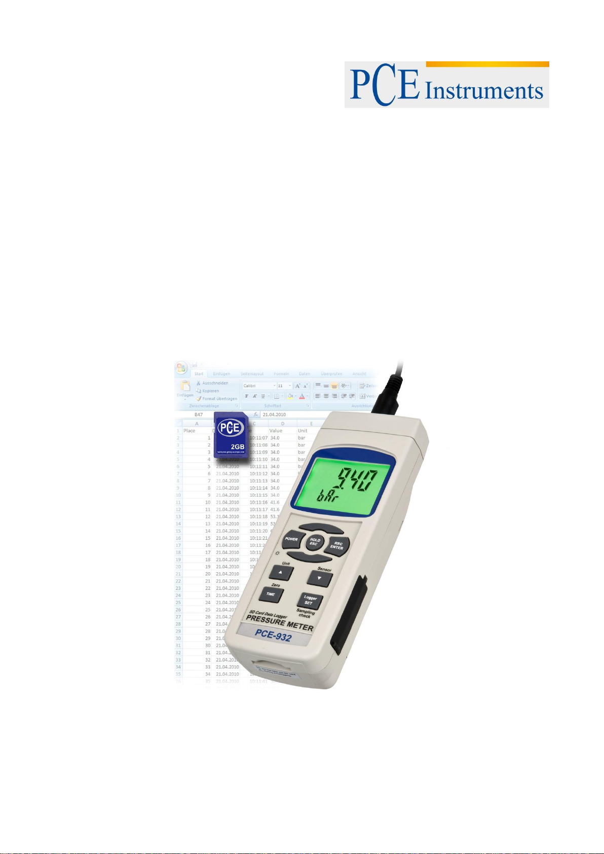
HVAC Meter PCE-932
Page 2

Manual
Contents
1 Introduction ............................................................................................................. 3
2 Safety notes ............................................................................................................. 3
3 Specifications .......................................................................................................... 4
3.1 General ....................................................................................................................................... 4
3.2 Electrical (23 ± 5 °C) ................................................................................................................... 4
4 System description ................................................................................................. 5
5 Sensor type selection ............................................................................................. 6
6 Measuring procedure .............................................................................................. 6
7 Other functions ....................................................................................................... 7
7.1 Data Hold .................................................................................................................................... 7
7.2 Data Record ( Max., Min. reading ) ............................................................................................ 7
7.3 LCD Backlight ON/OFF .............................................................................................................. 7
8 Datalogger ............................................................................................................... 7
8.1 Preparation before using the datalogger function ...................................................................... 7
8.2 Auto Datalogger (Set sampling time ≧ 1 second) ...................................................................... 8
8.3 Manual Datalogger ( Set sampling time = 0 second ) ................................................................ 8
8.4 How to check the time information ............................................................................................. 8
8.5 How to check the sampling time information .............................................................................. 8
8.6 SD card data structure ................................................................................................................ 9
9 Saving data from the SD card to the computer (EXCEL software) ..................... 9
10 Advanced settings ................................................................................................ 10
10.1 SD memory card format ........................................................................................................... 10
10.2 Set clock time (Year/Month/Date, Hour/Minute/Second) ......................................................... 11
10.3 Set sampling time (Hour/Minute/Second) ................................................................................. 11
10.4 Auto Power Off ......................................................................................................................... 11
10.5 Enable / disable beeper sound ................................................................................................. 11
10.6 Decimal point of SD card setting .............................................................................................. 12
10.7 Set the desired type of optional external pressure sensor ....................................................... 12
10.8 ESC .......................................................................................................................................... 12
11 Power supply by optional mains adaptor ........................................................... 12
12 Battery replacement .............................................................................................. 12
13 System reset .......................................................................................................... 13
14 RS-232 serial PC interface .................................................................................... 13
15 Disposal ................................................................................................................. 14
16 Contact ................................................................................................................... 14
16.1 PCE Instruments UK ................................................................................................................ 14
16.2 PCE Americas .......................................................................................................................... 14
2
Page 3

Manual
1 Introduction
Thank you for purchasing a PCE-932 from PCE Instruments.
* Meter can cooperate optional pressure sensor with 2, 5, 10, 20, 50, 100, 200, 400 Bar, new calibration
procedures are not necessary when change the new sensor.
* When change the new pressure sensor, just select pressure type ( 2, 5, 10, 20, 50, 100, 200, 400 bar )
on the front panel button. The sensor type will memorize into the circuit permanently.
* 10 kinds pressure units ( Bar, Psi, Kg/cm^2, mm Hg, inch Hg, meter H20, inch H20, Atmosphere, hPA,
kPA ), unit select by push button on the front panel.
* Full line optional pressure sensors are available.
* Cooperate the external pressure sensor that its output signal is 100 mV for full scale.
* Zero button on the front panel, easy adjust the zero value of pressure sensor.
* Separate pressure sensor, easy for remote measurement.
* Microprocessor circuit assures maximum possible accuracy, provides special functions and features.
* Real time SD memory card Datalogger, built-in Clock and Calendar, sampling time can set from 1 sec to
8 hour 59 min. 59 sec.
* Manual datalogger is available, during execute the manual datalogger function, it can set the different
location no. ( position 1 to position 99 ).
* Innovation and easy operation, computer is not need to setup extra software, after execute datalogger,
just take away the SD card from the meter and plug in the SD card into the computer, it can down load
the all the measured value with the time information ( year/month/date/hour/minute/second ) to the Excel
directly, the user can make the further data or graphic analysis by themselves.
* SD card capacity : 1 GB to 16 GB.
* LCD with green light backlight, easy reading.
* It can default auto power off or manual power off.
* Data hold, record max. and min. reading.
* Microcomputer circuit, high accuracy.
* Power by UM3/AA ( 1.5 V ) x 6 batteries or DC 9V adapter.
* RS232/USB PC computer interface.
* Wide applications : Measure pneumatic pressures, measure automobile engine pressures, pressure for
super heat measurements, hydraulic servo controls, refrigeration, air conditioning, food processing.
2 Safety notes
Please read this manual carefully and completely before you use the device for the first time. The device
may only be used by qualified personnel and repaired by PCE Instruments personnel. There is no
warranty of damages or injuries caused by non-observance of the manual.
- The device may only be used in the approved temperature range.
- The case should only be opened by qualified personnel of the PCE Instruments.
- The instrument should never be placed with the user interface facing an object (e.g. keyboard side on a
table).
- You should not make any technical changes to the device.
- The appliance should only be cleaned with a damp cloth / use only pH-neutral cleaner
This user's handbook is published by PCE Instruments without any guarantee.
We expressly point to our general guarantee terms which can be found in our general terms of business.
If you have any questions please contact PCE Instruments.
3
Page 4
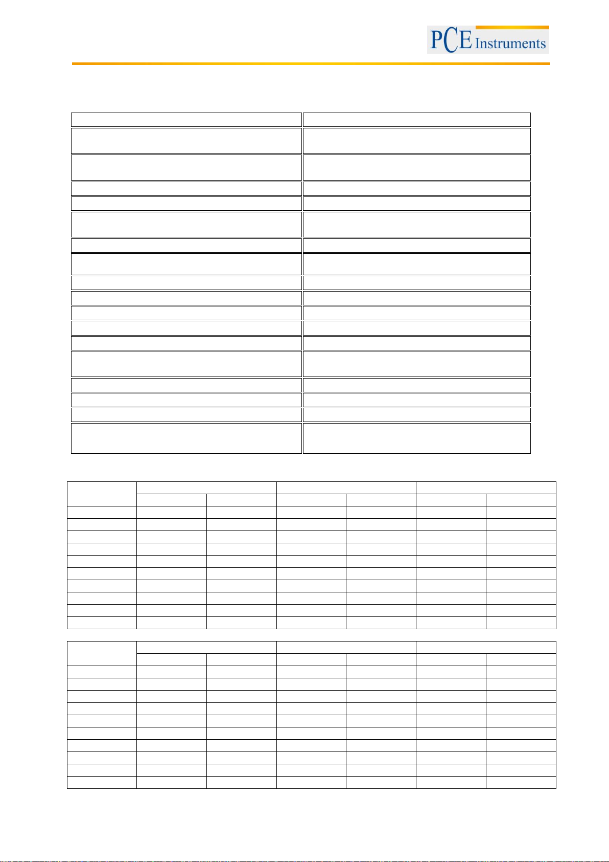
3 Specifications
Measurement range
0 to 400 bar (depending on the sensor)
Selectable units
bar, psi, kg/cm2, mm/Hg, inch/Hg,
meter/H2O, inch/H2O, atmosphere
Pressure connector
optional, 5V DC, maximum output of sensor is100
mV DC (see ranges below)
Zero reset
by way of keypad
Auto shut-off
yes (this function can be disabled)
Functions
measurement of pressure, Min and Max HOLD,
data transfer to a computer via RS-232 interface
Auto shut-off
to conserve battery power (can be disabled)
Rate of measurement
approx. every 0.8 seconds
Display
LCD display: 52 x 38 mm
Memory
SD card up to 16 GB (a 2 GB card is included)
Enclosure
ABS plastic
Software
optional (only for real time data transference)
Low battery indication
indicated on the display
Power supply
6 x 1,5 V AA batteries
mains cable (option)
Dimensions
177 x 68 x 45 mm
Peso
350 g
Operating temperature
0 to 50°C
Operating humidity
0 to 80% r.h.
Sensor type
2 bar
5 bar
10 bar
Max. range
Resolution
Max. range
Resolution
Max. range
Resolution
bar 2 0.002
5
0.005
10
0.01
Psi
29
0.02
72.5
0.1
145
0.2
Kg/cm^2
2.040
0.002
5.095
0.005
10.19
0.01
mm Hg
1500
2
3750
5
7500
10
inch Hg
59.05
0.05
147.6
0.1
295.2
0.2
meter H20
20.40
0.02
50.95
0.05
101.9
0.1
inch H20
802 1 2006
2
4010
5
Atmosphere
1.974
0.002
4.935
0.002
9.87
0.01
hPA
2000
2
5000
5
10000
10
kPA
200.0
0.2
500.0
0.5
1000
1
Sensor type
20 bar
50 bar
100 bar
Max. range
Resolution
Max. range
Resolution
Max. range
Resolution
bar
20
0.02
50
0.05
100
0.1
Psi
290
0.2
725 1 1450
2
Kg/cm^2
20.40
0.02
50.95
0.05
101.9
0.1
mm Hg
15000
20
37500
50
75000
100
inch Hg
590.5
0.5
1476
1
2952
2
meter H20
204.0
0.2
509.5
0.5
1019
1
inch H20
8020
10
20050
20
40100
50
Atmosphere
19.74
0.02
49.35
0.05
98.7
0.1
hPA
20000
20
50000
50
10000
100
kPA
2000
2
5000
5
1000
10
3.1 General
Manual
3.2 Electrical (23 ± 5 °C)
4
Page 5
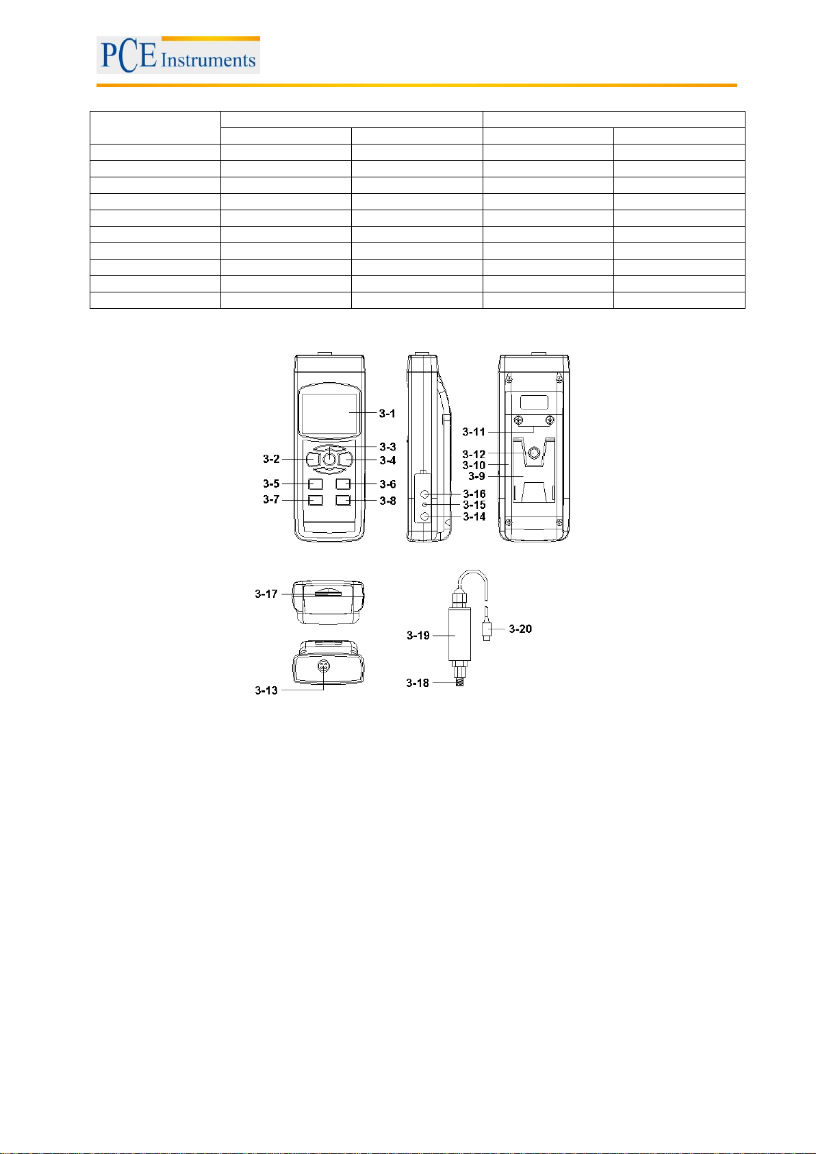
Sensor type
200bar
400 bar
Max. range
Resolution
Max. range
Resolution
bar
200
0.2
400
0.5
Psi
2900
2
5800
5
Kg/cm^2
204.0
0.2
408.0
0.5
mm Hg
150000
200
300000
500
inch Hg
5905
5
11810
10
meter H20
2040
2
4075
5
inch H20
80200
100
160600
200
Atmosphere
197.4
0.2
394.5
0.5
hPA
200000
200
400000
500
kPA
20000
20
40000
50
4 System description
Manual
3-1 Display
3-2 Power Button ( Backlight Button )
3-3 Hold Button ( ESC Button )
3-4 REC Button ( Enter Button )
3-5 Unit Button ( ▲ Button )
3-6 Sensor type Button ( ▼ Button )
3-7 Zero Button ( Time Button )
3-8 Logger Button ( SET Button, Sampling check )
3-9 Stand
3-10 Battery Compartment/Cover
3-11 Battery Cover Screw
3-12 Tripod Fix Nut
3-13 Probe Socket
3-14 DC 9V Power Adapter Input Socket
3-15 Reset Button
3-16 RS-232 Output Terminal
3-17 SD card socket
3-18 Port Connector of Pressure Sensor
3-19 Pressure Sensor Main body
3-20 Plug of Pressure Sensor
5
Page 6
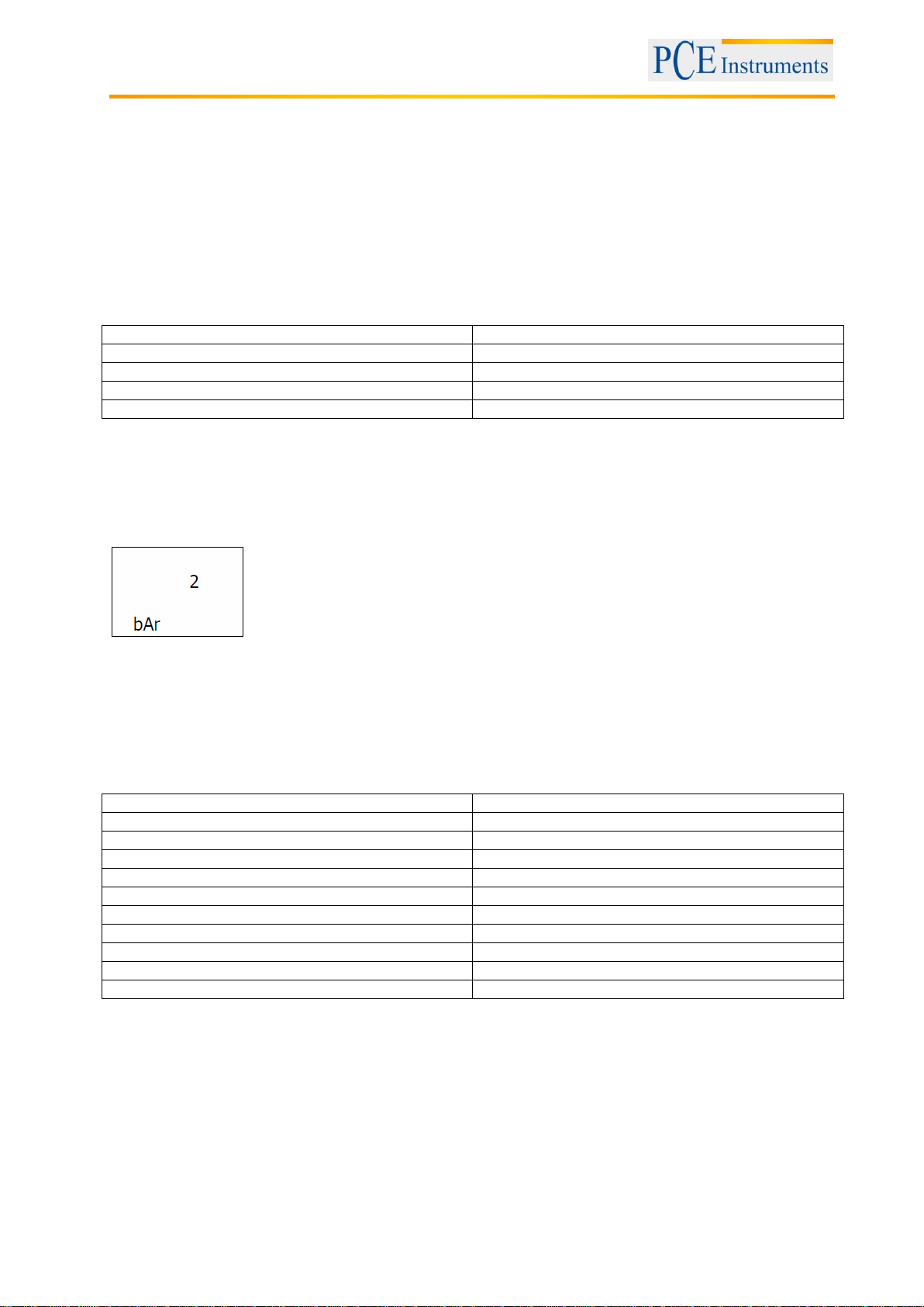
Manual
Thread
1/4”
Maximum temperature
80 °C
Dimensions
30 mm diameter x 85 mm long
Weight
160 g
Connecting cable
1.2 m
Unit
Display indication
Psi
PSI
Inch Hg
In Hg
Inch H2O
In H2O
hPA
hPA
KPA
_PA
Bar
bAr
Kg/cm^2
_g C2
Mm Hg
-- Hg
Meter H2O
-t H2O
Atmosphere
AtP
5 Sensor type selection
The meter can cooperate with optional 2, 5, 10, 20, 50, 100, 200, 400 bar sensor, new calibration is not
necessary when changing the new sensor.
Those different optional pressure sensor are :
* 5 bar pressure sensor, Model : PS100-5
* 20 bar pressure sensor, Model : PS100-20
* 50 bar pressure sensor, Model : PS100-50
* 100 bar pressure sensor, Model : PS100-100
* 400 bar pressure sensor, Model : PS100-400
After already select the convenient pressure sensor type,
press Sensor type Button (3-6) once, the Display will show the sensor type to confirm.
For example, if the pressure type already select 2 bar pressure sensor ( Model : PS100-2BAR ), then
if press Sensor type Button (3-6) once, the Display will show :
6 Measuring procedure
1) Plug in the " Plug of Pressure Sensor " (3-20) to meter's " Probe Input Socket " (3-13)
2) Power on the meter by pushing the " Power Button " (3-2) once.
3) Press the " Sensor Type Button " (3-6) once to check if the meter's sensor type is same as the external
pressure sensor.
4) Press the " Unit Button " (3-5) once in sequence to select the measuring unit as : Bar, Psi, Kg/cm^2,
mm Hg, inch Hg, meter H20, inch H20, Atmosphere, hPA, kPA.
Note:
After select the desired unit, power off the meter then power on again, the meter circuit memory
will save the selected unit with default.
5) Zero adjustment: If the Display is not show zero value, push the " Zero Button " (3-7), > 10 seconds
continuously, the Display value will change to zero value.
6) Connect the " Port Connector of Pressure Sensor "(3-18) to the installation that intend to measure the
pressure value.
7) Apply the pressure, meter will show the pressure value.
6
Page 7

Manual
The numerical data structure of SD card is default used the " . " as the decimal, for
example "20.6" "1000.53" . But in certain countries ( Europe ...) is used the " , " as the
decimal point, for example " 20, 6 ", "1000,53". Under such situation, it should
change the Decimal character at first, details of setting the Decimal point can be
found further down.
7 Other functions
7.1 Data Hold
During the measurement, press the " Hold Button " (3-3) once will hold the measured value & the LCD will
display a " HOLD " symbol. Press the " Hold Button " once again will release the data hold function.
7.2 Data Record ( Max., Min. reading )
1) The data record function records the maximum and minimum readings. Press the " REC Button " (3-4)
once to start the Data Record function and there will be a " REC " symbol on the display.
2) With the " REC " symbol on the display :
a) Press the " REC Button " (3-4) once, the " REC MAX " symbol along with the maximum value
will appear on the display. If intend to delete the maximum value, just press the " Hold Button " (3-3)
once, then the display will show the " REC " symbol only & execute the memory function continuously.
b) Press the " REC Button " (3-4) again, the " REC MIN " symbol along with the minimum value will
appear on the display. If intend to delete the minimum value, just press the " Hold Button " (3-3) once,
then the display will show the " REC " symbol only & execute the memory function continuously.
c) To exit the memory record function, just press the " REC Button " for 2 seconds at least. The display
will revert to the current reading.
7.3 LCD Backlight ON/OFF
After power ON, the " LCD Backlight " will light automatically. During the measurement, press the
" Backlight Button " (3-2) once will turn OFF the " LCD Backlight ". Press the " Backlight Button " once
again will turn ON the " LCD Backlight " again.
8 Datalogger
8.1 Preparation before using the datalogger function
a. Insert the SD card
* It is recommended to use memory card ≦ 4 GB.
Prepare a " SD memory card " ( 1 GB to 16 GB, optional ), insert the SD card into the " SD card
socket" (3-17). The front panel of the SD card should face against the down case.
b. SD card Format
If SD card just the first time use into the meter, it is recommended to make the " SD card Format " first,
see further down.
* It recommend strongly, do not use memory cards that have been formatted by other meter or by a
computer. Reformat the memory card with your meter.
c. Time setting
If the meter is used at first time, it should to adjust the clock time exactly, see further down.
d. Decimal format setting
7
Page 8

Manual
8.2 Auto Datalogger (Set sampling time ≧ 1 second)
a. Start the datalogger
Press the " REC Button (3-4) once , the LCD will show the text " REC ", then press the " Logger Button
"(3-8), the bottom text " DATALOGGER " will flashing, at the same time the measuring data along the
time information will be saved into the memory circuit.
Note:
You can find some more information on how to set the sampling time and the beeper sound
further down.
b. Pause the datalogger
During execute the Datalogger function , if press the " Logger Button " (3-8) once will pause
the Datalogger function ( stop to save the measuring data into the memory circuit temporally ). In the
same time the text of " DATALOGGER " will be no flashing.
Note:
If press the " Logger Button " (3-8) once again will execute the Datalogger again, the bottom text
of "DATALOGGER " will flash.
c. Finish the datalogger
During pause the Datalogger, press the " REC Button " (3-4) continuously at least two seconds, the
"REC " indication will be disappeared and finish the Datalogger.
8.3 Manual Datalogger ( Set sampling time = 0 second )
a. Set sampling time to 0 second
Press the " REC Button (3-4) once , the LCD will show the text " REC ", then press the " Logger
Button" (3-8) once, the bottom text " DATALOGGER " will flashing once and Beeper will sound once, at
the same time the measuring data along the time information will be saved into the memory circuit. The
lower Display will show the Position ( Location ) no. and saved into the SD card too.
Note:
During execute the Manual Datalogger, press the " ▲ Button " (3-5) the lower no. ( position no. )
will flashing. It can use the " Button " (▲ 3-5,) or "▼ Button " (3-6) to set the measuring Location
no. ( 1 to 99, for example room 1 to room 99 ) to identify the measurement location , the lower
Display will show P x ( x = 1 to 99 ).
b. Finish the datalogger
Press the " REC Button " (3-4) continuously at least two seconds, the " REC " indication will be
disappeared and finish the Datalogger.
8.4 How to check the time information
During the normal measurement screen ( not execute the Datalogger ),
1) If press " Time Button " (3-7) once , the lower LCD display will present the time information of
Hour/Minute/Second ( h.m.s ) in the lower Display.
2) If press " Time Button " (3-7) once again , thelower LCD display will present the time information of
Year/Month/Date ( yy.mm.dd ) in the lower Display.
3) If press " Time Button " (3-7) once again, the LCD will return to normal screen.
8.5 How to check the sampling time information
During the normal measurement screen ( not execute the Datalogger ), If press " Sampling Button " (3-8)
once , the lower LCD display will present the Sampling time information in second unit.
8
Page 9
Manual
8.6 SD card data structure
1) When the SD card is used into the meter, the SD card will generate a route:
PSA01
2) If the first time to execute the Datalogger, under the route PSA01\, will generate a new file name
PSA01001.XLS. After exist the Datalogger, then execute again, the data will save to the
PSA01001.XLS until Data column reach to 30,000 columns, then will generate a new file, for example
PSA01002.XLS
3) Under the folder PSA01\, if the total files more than 99 files, will generate anew route, such as
PSA02\........
4) The file's route structure :
PSA01\
PSA01001.XLS
PSA01002.XLS
.....................
PSA01099.XLS
PSA02\
PSA02001.XLS
PSA02002.XLS
.....................
PSA02099.XLS
PSAXX\
.....................
.....................
Note:
XX : Max. value is 10.
9 Saving data from the SD card to the computer (EXCEL software)
1) After execute the Data Logger function, take away the SD card out from the " SD card socket " (3-17).
2) Plug in the SD card into the Computer's SD card slot ( if your computer build in this installation ) or
insert the SD card into the " SD card adapter ". then connect the " SD card adapter " into the computer.
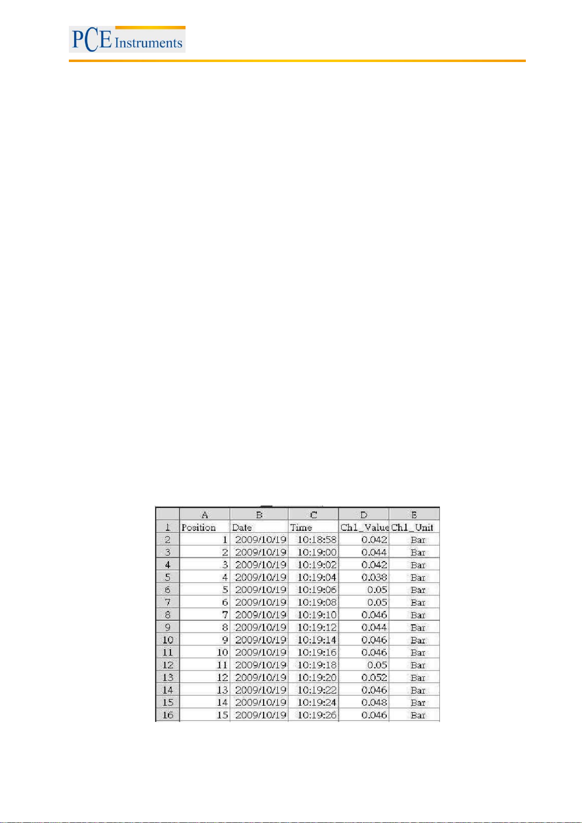
3) Power ON the computer and run the " EXCEL software ". Down load the saving data file ( for example
the file name : PSA01001.XLS, PSA01002.XLS ) from the SD card to the computer. The saving data
will present into the EXCEL software screen ( for example as following EXCEL data screens ) , then
user can use those EXCEL data to make the further Data or Graphic analysis usefully.
Example EXCEL data screen
9
Page 10
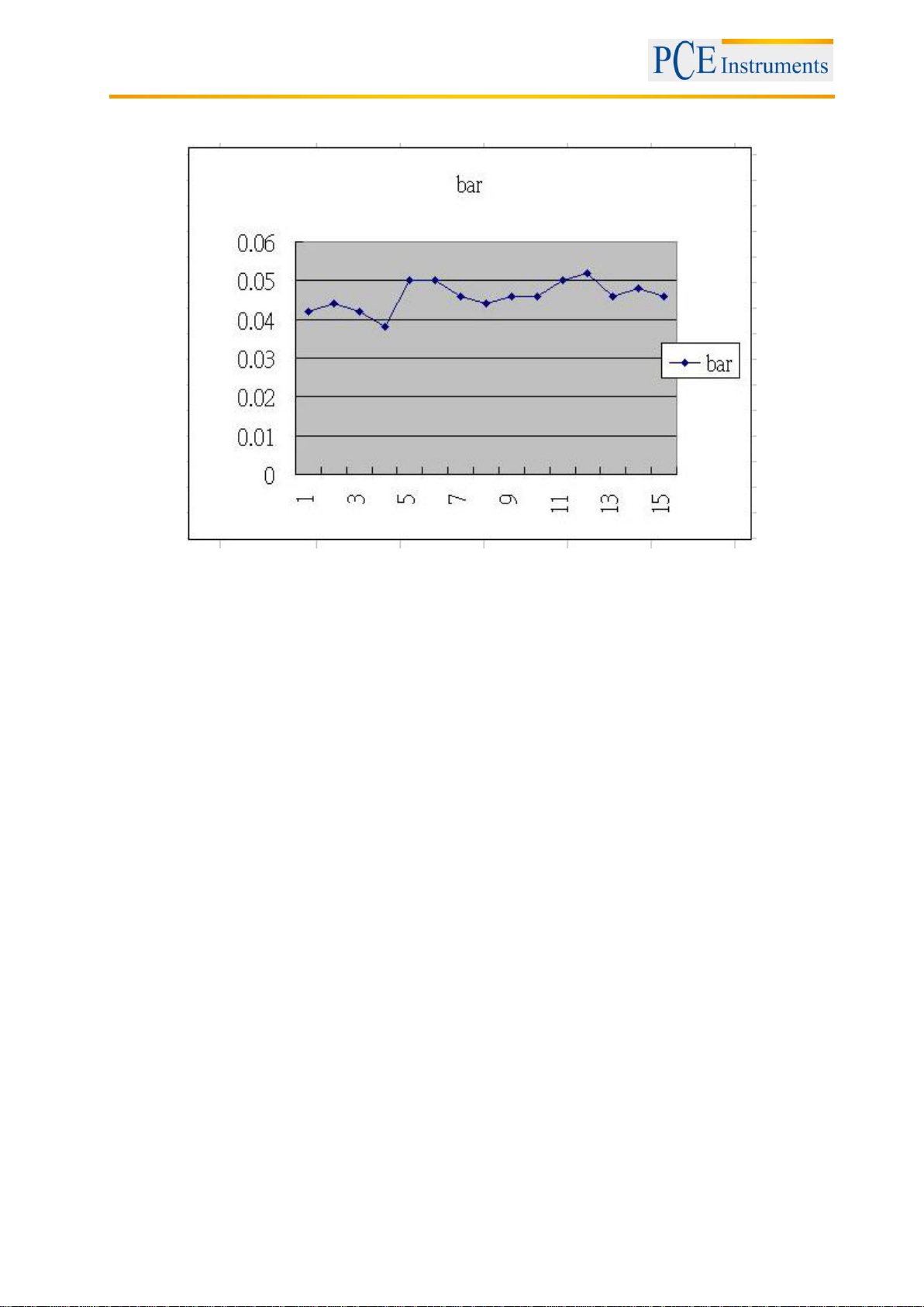
Example EXCEL graphics screen
Manual
10 Advanced settings
Under do not execute the Datalogger function, press the " SET Button " (3-8) continuously at least two
seconds will enter the " Advanced Setting " mode. Then press the " SET Button " (3-8) once a while
in sequence to select the eight main function, the display will show :
Sd F..... SD memory card Format
dAtE..... Set clock time ( Year/Month/Date, Hour/Minute/Second )
SP-t.......Set sampling time ( Hour/Minute/Second )
PoFF..... Auto power OFF management
bEEP.....Set beeper sound ON/OFF
dEC.......Set SD card Decimal character
tyPE...... Set the external optional sensor type
ESC...... Escape from the advanced setting
Note:
During execute the " Advanced Setting " function, if press " ESC Button " (3-3) will exit the
" Advanced Setting " function, the LCD will return to normal screen.
10.1 SD memory card format
When the lower display shows " Sd F "
1) Use the " ▲ Button " (3-5,) or " ▼ Button " (3-6) to select the upper value to " yES " or " no ".
yES - Intend to format the SD memory card
no - Not execute the SD memory card format
2) If select the upper to " yES ", press the " Enter Button" (3-4) once again, the Display will show text
" yES Enter " to confirm again, if make sure to do the SD memory card format, then press " Enter
Button " once will format the SD memory clear all the existing data that already saving into the SD card.
10
Page 11

Manual
10.2 Set clock time (Year/Month/Date, Hour/Minute/Second)
When the upper display shows " dAtE "
1) Use the " ▲ Button " (3-5) or " ▼ Button "(3-6) to adjust the value ( Setting start from Year value ).
After the desired value is set, press the " Enter Button " (3-4) once will going to next value adjustment
(for example, first setting value is Year then next to adjust Month, Date, Hour, Minute, Second value ).
Note:
The adjusted value will flash.
2) After set all the time value ( Year, Month, Date, Hour, Minute, Second ), press the " SET Button " (3-8)
once will save the time value, then the screen will jump to Sampling time " setting screen (see further
down).
Note:
After the time value is setting, the internal clock will run precisely even Power off if the battery is
under normal condition (No low battery power).
10.3 Set sampling time (Hour/Minute/Second)
When the upper display shows " SP-t "
1) Use the " ▲ Button " (3-5) or " ▼ Button " (3-6) to adjust the value ( Setting start from Hour value ).
After the desired value is set, press the " Enter Button " (3-4) once will going to next value adjustment
(for example, first setting value is Hour then next to adjust Minute, Second value ).
Remark :
The adjusted value will be flashed.
2) After set all the sampling time value ( Hour, Minute,Second ), press the " SET Button " (3-8) once will
save the sampling value with default then the screen will jump to " Auto power OFF " setting screen
(see further down).
10.4 Auto Power Off
When the lower display shows " PoFF "
1) Use the " ▲ Button " (3-5) or " ▼ Button "(3-6) to select the upper value to " yES " or " no ".
yES - Auto Power Off management will enable.
no - Auto Power Off management will disable.
2) After select the upper text to " yES " or " no ", press the " Enter Button " (3-4) will save the setting
function with default.
10.5 Enable / disable beeper sound
When the lower display shows " bEEP "
1) Use the " ▲ Button " (3-5) or " ▼ Button " (3-6) to select the upper value to " yES " or " no ".
yES - Meter's beep sound will be ON with default.
no - Meter's beep sound will be OFF with default.
2) After select the upper text to " yES " or " no ", press the " Enter Button " (3-4) will save the setting
function with default.
11
Page 12

Manual
10.6 Decimal point of SD card setting
The numerical data structure of SD card is default used the " . " as the decimal, for example "20.6"
"1000.53". But in certain countries ( Europe ...) is used the " , " as the decimal point, for example " 20,6 "
"1000,53". Under such situation, it should change the Decimal character at first.
When the lower display shows " dEC "
1) Use the " ▲ Button " (3-5) or " ▼ Button " (3-6) to select the upper text to " bASIC " or " Euro ".
bASIC - Use " . " as the Decimal point with default.
Euro - Use " , " as the Decimal point with default.
2) After select the upper text to " bASIC " or " Euro ", press the " Enter Button " (3-4) will save the setting
function with default.
10.7 Set the desired type of optional external pressure sensor
When the lower display show " tyPE "
1) Use the " ▲ Button " (3-5) or " ▼ Button " (3-6) to select the upper Display no. to 2, 5, 10 20. 50, 100,
200 or 400.
Selecting no. via the optional pressure sensor type :
If the selected no. is " 5 " . The meter will cooperate :
5 bar pressure sensor, Model : PS100-5
If the selected no. is " 20 " . The meter will cooperate :
20 bar pressure sensor, Model : PS100-20
If the selected no. is " 50 " . The meter will cooperate :
50 bar pressure sensor, Model : PS100-50
If the selected no. is " 100 " . The meter will cooperate :
100 bar pressure sensor, Model : PS100-100
If the selected no. is " 400 " . The meter will cooperate :
400 bar pressure sensor, Model : PS100-400
2) After Display the convenient pressure sensor type is selected to , press the " Enter Button " (3-4)
will save the setting function with default.
10.8 ESC
When the display shows " ESC "
When the Display show the text " ESC ", then press the " SET Button " (3-8) or " ESC Button " (3-3) will
finish the Advanced Setting procedures.
Note:
During execute the " Advanced Setting " function, if press " ESC Button " (3-3) will exit the "
Advanced Setting " function, the LCD will return to normal screen.
11 Power supply by optional mains adaptor
The meter also can supply the power supply from the DC 9V Power Adapter ( optional ). Insert the plug of
Power Adapter into " DC 9V Power Adapter Input Socket" (3-14). The meter will permanent power ON
when use the DC ADAPTER power supply ( The power Button function is disabled ).
12 Battery replacement
1) When the left corner of LCD display shows " ", it is necessary to replace the battery. However, in
spec. measurement may still be made for several hours after low battery indicator appears before the
instrument become inaccurate.
2) Loose the screws of the " Battery Cover " (3-11) and take away the " Battery Cover " from the
Instrument and remove the battery.
3) Replace with DC 1.5 V battery ( UM3, AA, Alkaline/heavy duty ) x 6 PCs, and reinstate the cover.
4) Make sure the battery cover is secured after changing batteries.
12
Page 13
Manual
D15
Start Word
D14
4
D13
When send the upper display data = 1
When send the lower display data = 2
D12, D11
Annunciator for display
Bar = 22
Mm Hg = 78
Inch H2O = 25
Psi = 23
Inch Hg = 80
ATP = 26
Kg/cm^2 = 77
Meter H2O = 79
hPA = 91
kPA = 88
D10
Polarity
0 = Positive 1 = Negative
D9
Decimal Point(DP), position from right to the left
0 = No DP, 1= 1 DP, 2 = 2 DP, 3 = 3 DP
D8 to D1
Display reading, D1 = LSD, D8 = MSD
For example:
If the display reading is 1234, then D8 to
D1 is : 00001234
D0
End Word
Baud rate
9600
Parity
No parity
Data bit no.
8 data bits
Stop bit
1 stop bit
13 System reset
If the troubles such as the following arise:
CPU system is hold ( for example, the key button cannot be operated... ).
Then make the system RESET will fix the problem. The system RESET procedures will be either
following method:
During the power on, use a pin to press the " Reset Button "
(3-15) once a while will reset the circuit system.
14 RS-232 serial PC interface
The instrument has RS232 PC serial interface via a 3.5 mm terminal (3-16).
The data output is a 16 digit stream which can be utilized for user's specific application.
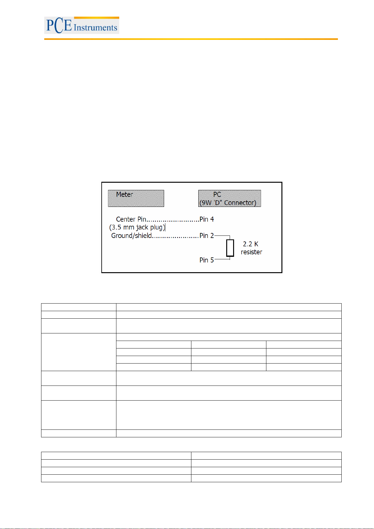
An RS-232 lead with the following connection will be required to link the instrument with the PC serial
port.
The 16 digits data stream will be displayed in the following format :
D15 D14 D13 D12 D11 D10 D9 D8 D7 D6 D5 D4 D3 D2 D1 D0
Each digit indicates the following status:
RS-232 format: 9600, N, 8, 1
13
Page 14

Manual
15 Disposal
For the disposal of batteries, the 2006/66/EC directive of the European Parliament applies. Due to the
contained pollutants, batteries must not be disposed of as household waste. They must be given to
collection points designed for that purpose.
In order to comply with the EU directive 2012/19/EU we take our devices back. We either re-use them or
give them to a recycling company which disposes of the devices in line with law.
If you have any questions, please contact PCE Instruments.
16 Contact
If you have any questions about our range of products or measuring instruments please contact PCE
Instruments.
16.1 PCE Instruments UK
By post:
PCE Instruments UK Ltd.
Units 12/13 Southpoint Business Park
Ensign Way, Southampton
Hampshire
United Kingdom, SO31 4RF
By phone:
02380 987 035
16.2 PCE Americas
By post:
PCE Americas Inc.
711 Commerce Way
Suite 8
Jupiter
33458 FL
USA
By phone:
561 320 9162
14
 Loading...