


Manual
HVAC Meter PCE-423
Version 1.0
Date of creation: 10.02.2015
Date of last change: 17.06.2015
PCE Americas Inc.
711 Commerce Way
Suite 8
Jupiter
FL-33458
USA
From outside US: +1
Tel: (561) 320-9162
Fax: (561) 320-9176
info@pce-americas.com
www.pce-instruments.com/english
www.pce-instruments.com
PCE Instruments UK Ltd.
Units 12/13
Southpoint Business Park
Ensign way
Hampshire / Southampton
United Kingdom, SO31 4RF
From outside UK: +44
Tel: (0) 2380 98703 0
Fax: (0) 2380 98703 9
info@pce-instruments.com

Contents
1 Introduction ............................................................................................................. 3
2 Safety notes ............................................................................................................. 3
3 Specification ............................................................................................................ 4
3.1 Technical specifications ......................................................................................................... 4
3.2 Contents of delivery ............................................................................................................... 4
4 System description ................................................................................................. 5
4.1 Display .................................................................................................................................. 5
4.2 Buttons .................................................................................................................................. 6
5 Operation ................................................................................................................. 6
5.1 Performing a measurement .................................................................................................... 6
5.2 Measuring functions ............................................................................................................... 9
5.2.1 Averaging over a certain amount of readings ............................................................................. 9
5.2.2 Averaging over a certain period of time ..................................................................................... 9
5.2.3 Hold function ............................................................................................................................. 9
5.2.4 MIN / MAX function ................................................................................................................... 9
5.3 Exchange the battery ............................................................................................................10
6 Setup ...................................................................................................................... 10
6.1 Set the unit of the cross-sectional area (UNIT) ......................................................................10
6.2 Adjust the value of the cross-sectional area (AREA) ..............................................................12
6.3 Activate/deactivate the auto shut-off function (SLP)...............................................................12
7 Software ................................................................................................................. 13
8 Contact ................................................................................................................... 14
8.1 PCE Instruments UK .............................................................................................................14
8.2 PCE Americas ......................................................................................................................14

Manual
3
1 Introduction
Thank you for purchasing an anemometer from PCE Instruments.
The PCE-423 anemometer with a thermal sensor stands out for its excellent price/performance ratio. The
PCE-423 anemometer has a high resolution and can be used for different purposes. This PCE-423
anemometer is a part of the basic equipment for professionals working with ventilation systems. The
PCE-423 anemometer is also used in institutional research and development. The thin probe (8 mm
diameter) makes it possible to use the anemometer in areas with a minimum range of measurement,
such as the inside of refrigeration units. Additionally, the PCE-423 anemometer has a telescopic probe
with a max. length of 1 m. Both the USB cable and the software (included in the delivery) allow to connect
the PCE-423 anemometer to a PC or laptop to transfer data continuously. Data can be stored in either txt
or csv format for further analysis.
2 Safety notes
Please read this manual carefully and completely before you use the device for the first time. The device
may only be used by qualified personnel and repaired by PCE Instruments personnel. There is no
warranty of damages or injuries caused by non-observance of the manual.
- The device may only be used in approved temperature ranges.
- The case should only be opened by qualified personnel of PCE Instruments.
- The instrument should never be placed with the user interface facing an object (e.g. keyboard side on a
table).
- You must not make any technical changes to the device.
- The appliance should only be cleaned with a damp cloth / use only pH-neutral cleaner.
This manual is published by PCE Instruments without any guarantee.
We expressly point to our general guarantee terms which can be found in our general terms of business.
If you have any questions please contact PCE Instruments.

Manual
4
3 Specification
3.1 Technical specifications
Measurement specifications
Sampling rate
approx. 1 / 0.8 s
Measurement range
Wind speed
0.1 … 25.0 m/s
20 … 4925 ft/min
0.2 … 48.5 knots
0.3 … 90 km/h
0.2 … 55.8 mph
Temperature
0.0 … +50.0 °C
Resolution
Wind speed
0.01 m/s
1 ft/min
0.1 knots
0.1 km/h
0.1 mph
Temperature
0.1 °C
Accuracy
Wind speed
± 5 % ± 1 digit (of measured value)
Temperature
± 1 °C
General specifications
Thermal probe
Telescopic probe
Length: 185 … 1000 mm
Max. diameter: 12 mm
Min. diameter: 10 mm
Interface
USB
Display
LCD display (46.7 x 60 mm)
Power supply
1 x 9 V battery
Case
ABS plastic
Auto Power Off
After 5 min of inactivity
Operating conditions
0 … +50 °C , < 80 % RH
Dimensions
210 x 75 x 50 mm
Weight
280 g
3.2 Contents of delivery
1 x anemometer PCE-423 with telescopic probe
1 x software
1 x USB data cable
1 x mains adapter
1 x 9 V battery
1 x instruction manual
1 x carrying case

Manual
5
4 System description
4.1 Display
1. Low battery indication
2. Main display; shows air velocity, saved data or time
3. Measuring unit air velocity (m/s; ft/min; km/h; MPH; knots)
4. Parameters secondary display: air flow (FLOW), air velocity (VEL), temperature (TEMP) or crosssectional area (AREA)
5. Secondary display; shows flow rate, air velocity, temperature or cross-sectional area
6. Indication for recording (REC) or maximum / minimum value (MAX / MIN)
7. Icon for averaging over a certain amount of readings
8. Mean value icon
9. Icon for averaging over a certain period of time
10. Multiplier for secondary display (x 100)
11. Flow rate unit (CFM or CMM)
12. Temperature unit (°C / °F)
13. Unit of flow cross-sectional area
14. Multiplier for main display
15. Auto Power Off symbol
16. Format of time indication
17. Hold function icon
18. Setup icon

Manual
6
4.2 Buttons
Button
Function
Turn the device on / off
Freeze/unfreeze the current reading on the
display (Hold)
Press and hold to adjust the zero point
(Zero)
Enter a folder in setup menu
Confirm an adjustment
Turn the backlight on / off
Press and hold it for 3 seconds to enter
setup menu
Choose the measuring unit for the main
display (m/s, ft/min, km/h, mph, knots)
Move up in setup menu
Choose the measuring unit for the
secondary display (°C, °F)
Move down in setup menu
Press to start averaging (over a certain
time or amount of readings)
Press to retrieve the maximum / minimum
value of a measurement
Press and hold for 2 seconds to go back to
normal mode
Press to change between flow rate and
temperature indication on the secondary
display
5 Operation
5.1 To carry out a measurement
1. Connect the sensor to the anemometer. Note the marks on the plug and the device.
2. Turn on the device by pressing . A counter appears on the display. After the counter has
reached “0”, the device is ready to use.
3. Choose the measuring units for air velocity and temperature. Press to switch between the
air velocity units on the main display (m/s, ft/min, km/h, mph, knots). Press to switch
between the temperature units on the secondary display (°C, °F).
4. Set the zero point. To do so, please make sure that the metal protection ring on the sensor head
is in the upper position (air velocity = 0). If this is the case, press and hold . (Fig. 1)

Manual
7
5. Move the protection ring to the lower position (Fig. 2). Use the telescopic stick (Fig. 3) to adjust
the sensor to the desired length. Remember to carefully insert the sensor cable into the
telescopic tube when extending it, to prevent damage to the cable.
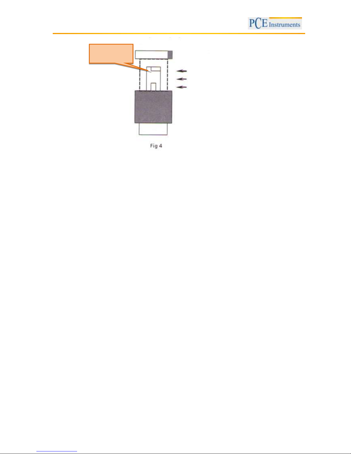
6. On top of the sensor, you can find arrows which indicate the flow direction. Please make sure that
these arrows are in line with the actual flow direction (Fig. 4). Now you can see the flow rate
on the main display and the temperature on the secondary display.
Protection ring
in upper
position
Air velocity
sensor
Manual
8
Flow rate
sensor
flow
direction

Manual
9
5.2 Measuring functions
5.2.1 Averaging over a certain amount of readings
Press and the current measurement value will appear on the secondary display. By means of the
key you can change the measuring unit. To include this value in the calculation, press . You
can repeat this procedure with as many readings as you wish to.
To finish averaging, press . Now the mean value will appear on the secondary display and the
“MEAN” indication on the display starts flashing. To return to normal measuring mode, please press
again.
5.2.2 Averaging over a certain period of time
Press and hold for 2 seconds until the time (mm:ss) is indicated on the main display. The current
measuring value now appears on the secondary display. To change the measuring unit, press .
After doing so, you can start averaging by pressing . The time indication in the main display starts
to run. You can also pause (and resume) averaging at any time by pressing . To finish averaging,
press . Now the mean value will appear on the secondary display and the “MEAN” indication on the
display starts flashing. To return to normal measuring mode, please press again.
5.2.3 Hold function
Press to freeze the current reading on the display. A “HOLD” indication appears on the display. To
unfreeze the reading, press again.
5.2.4 MIN / MAX function
Press once to show and hold the maximum value on the display. Press again to show and
hold the minimum value. In addition, a “REC” indication and the indications “MAX” or “MIN” appear on the
display. To exit this function and return to the normal measuring mode, press and hold for 2
seconds.
Manual
10
5.3 To replace the battery
To replace the battery, make sure that the device is turned off. Now move the cover of the battery
compartment downwards, while you push the mark on the cover. After that, you can carefully remove the
cover and remove the battery by releasing it carefully from the plug-in connectors. Next, insert a new
battery and slide the cover of the battery compartment upwards to close it.
6 Setup
To access the setup menu, press and hold for 3 seconds. Now the “SETUP” indication appears.
To exit the setup menu, press and hold again for 3 seconds.
In the setup menu you have the following options:
“UNIT” – Here you can choose the unit of the cross-sectional area. You can switch between in²,
m² and ft².
“AREA” – Here you can adjust the cross-sectional area.
“SLP” – Here you can activate / deactivate the Auto Power Off function.
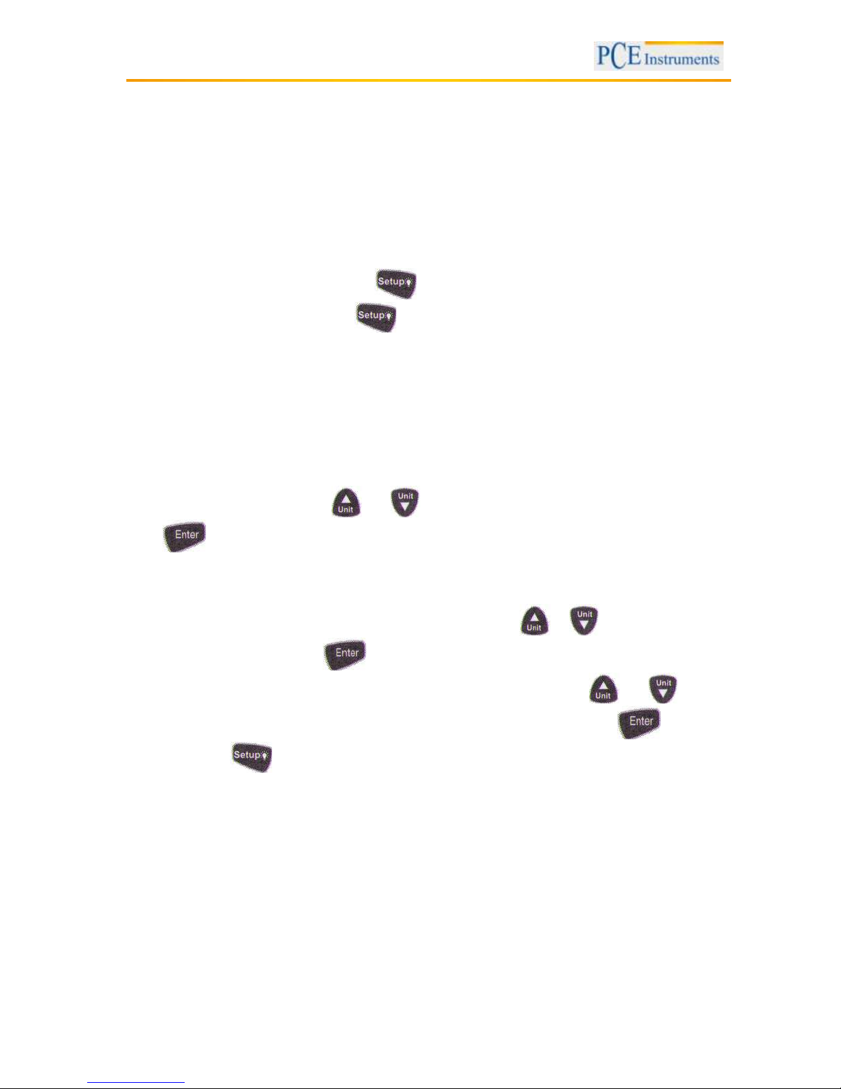
To navigate through the menu, use and until you see the desired option on the display. Then,
press to confirm.
6.1 Set the unit of the cross-sectional area (UNIT)
To access the unit selection screen for the cross-sectional area, use or until the display
shows “UNIT” (Fig. 1). Now press to confirm. An “AREA” indication should appear on the display.
This means that you can now select the unit of the cross-sectional area by using and . The
selected unit is shown next to the “AREA” indication. To confirm your selection, press . To exit the
setup menu, hold for 3 seconds.

Manual
11

Manual
12
6.2 Adjust the value of the cross-sectional area (AREA)
To access the adjustment screen of the cross-sectional area, use and until the display
indicates “AREA”, the unit and the actual value of the cross-sectional area (Fig. 3). Then press to
confirm. The digits on the screen start to flash. Now you can set the decimal point by using and
to navigate through the digits. To confirm the decimal point position, press . After that, the
last digit starts to flash. You can now set its value (from 0 to 9) by using and . Again, press
to confirm. The next digit starts to flash and you can set its value as described above. Repeat this
procedure until you have set the desired values for all digits. After confirming all settings, you can exit the
setup menu by holding for 3 seconds.
6.3 Activate/deactivate the Auto Power Off function (SLP)
To access the setting screen of the Auto Power Off function, use and , until the display shows
“SLP”. Then, press to confirm. Now you can choose between “ON” and “OFF” by using and
. To confirm your selection, press . After that you can leave the setup menu by holding
for 3 seconds.

Manual
13
7 Software
First, please install the software and the USB driver “CP2102 USB to UART Bridge Controller” from the
CD-ROM. If there are problems with the installation, you can find the driver installer
“CP210xVCPInstaller.exe” in the folder “driver” on the CD.
You can operate the anemometer via the PC software
Data recording starts automatically
You still have to adjust settings like the cross-sectional area on the device itself
You can select the parameters to be measured by using check fields
You can export, save and print the measured data

Manual
14
8 Contact
If you have any questions about our range of products or measuring instruments please contact PCE
Instruments.
8.1 PCE Instruments UK
By post:
PCE Instruments UK Ltd.
Units 12/13 Southpoint Business Park
Ensign Way, Southampton
Hampshire
United Kingdom, SO31 4RF
By phone:
02380 987 035
8.2 PCE Americas
By post:
PCE Americas Inc.
711 Commerce Way
Suite 8
Jupiter
33458 FL
USA
By phone:
561 3209162
 Loading...