

Page 1
PCE Americas Inc.
711 Commerce Way
Suite 8
Jupiter
FL-33458
USA
From outside US: +1
Tel: (561) 320-9162
Fax: (561) 320-9176
[email protected]
Manual
Climate Meter PCE-313
PCE Instruments UK Ltd.
Units 12/13
Southpoint Business Park
Ensign way
Hampshire / Southampton
United Kingdom, SO31 4RF
From outside UK: +44
Tel: (0) 2380 98703 0
Fax: (0) 2380 98703 9
www.pce-instruments.com/english
www.pce-instruments.com
Page 2

CONTENTS
TITLE
I. Saf
ety Informat
II. Introduction
III. Specifications
IV
. Symbol Definition and Button Location
V. Operation Instructions
4.1 Power-Up…………………………………………………
4.2 Humidity and Te
4.3 Selecting the Temperature Scale………………………………………………………..
4.4 Data-Hold Operation…………………
4.5 Dat
4.6 Clock Setup ………………………………………………………
4.7 Recor
4.8 Time Operation…………….
4.9 MAX/MIN Operation………
4.10 Auto Powe
1 Low Battery C
4.1
4.12 Digital Output…………………………
VI. Setup
RS232 interface software
PAGE
………………………………………………………………….….. 1
ion
…...……………………………………………………………………….….. 1
…………………………………………………………………………..
…………………………………………….…………..…… 3
mperature Measurement…………………………………………...... 3
aLogger………………………………………………
ding Interval
Setup……..………………………………………………………….
……………………………………………………………....
…………………………………………………………….….
r Off……………………………………………………………………………
ondition …………………………………………………………………..
TestLink (Humidity Temperature DataLogger)—
……………………………………………………...…
……………………………….. 2
……………………………….....
…………………………………………………....
…………………………………
………………………...
…………………………………………………..
3
4
\
.
1
3
3
3
3
4
4
4
4
4
7
Page 3
I. Safety Informa
Read the following safety informa
tion
tion carefully before attempting to operate or service the meter.
Use the meter only as specified in this manual; otherwise, the protection provided by the meter may
be impaired.
Environment conditions
Altitude up to 2000 meters
ο
ο Relatively
Operation Ambient 0 ~ 50℃
ο
humidity
90% max.
Maintenance & Clearing
Repairs or servicing not covered in this manual should only be performed by
ο
Periodically wipe the case wi
ο
th a dry cloth. Do not use abrasives or solvents on this instrument.
qualified personnel.
Safety symbols
Comply with EMC
Read safety Information first.
II. Introduction:
This instrument is a digital Humidity/Tempe
semiconductor sensor. This operations manual contains general product information and
specifications. Its internal memory can keep up to 16300 readings. (note1.) It uses a RS232
interface to perform bi-directional communication with PC.
rature meter that uses a polymer capacitive and
III. Specifications:
Numerical Display :
Measurement Range :
Resolution : 0.1%RH , 0.1℃,0.1℉
Accuracy :
Response Time :
Signal Output : RS-232 Data Output
Operating Environment : 0℃~50℃, 32℉~122℉ 0 to 90%RH non-condensing
Storage Environment : -10℃~60℃, 14℉~140℉ 0 to 80%RH non-condensing
Power Requirements :
Plug Diameter: 3.5 mm×1.35mm
Battery Life : Approx. 100hrs with alkaline battery
Weight : Approx.320g
note1:
Every time you press "REC" button to
4 digital Liquid Crystal Display.
Humidity: 0%~100%RH
Temperature: -20℃~+60℃ -
Humidity:±2.5%RH at 25℃
rature: ±0.7℃ ±1.4℉
Tempe
Humidity: 75 sec. In slowly movi
Temperature: 40 sec. in slowly moving air
Battery: One 9V battery 006p or IEC 6F
AC adapter: 9V
DC / 10mA minimum
start recording data and press "REC" button again to stop
4℉~+140℉
ng air
22 or NEDA1604
Page 4
recording, there will be a data set in
memory, you can store as many data sets as you want until memory
is full.
Dimension :
Me
ter = 186(L
W)×30(H)mm ; 10.8(L)×2.5
)×64(
(W)×1.2(H)inch
Probe = 190(L)×15(D)mm ; 7.5(L)×0.6(D)inch
Accessories : Instruction Manual, 9V Battery, Carrying Case, Software, RS-232 Cable, Probe
Holder.
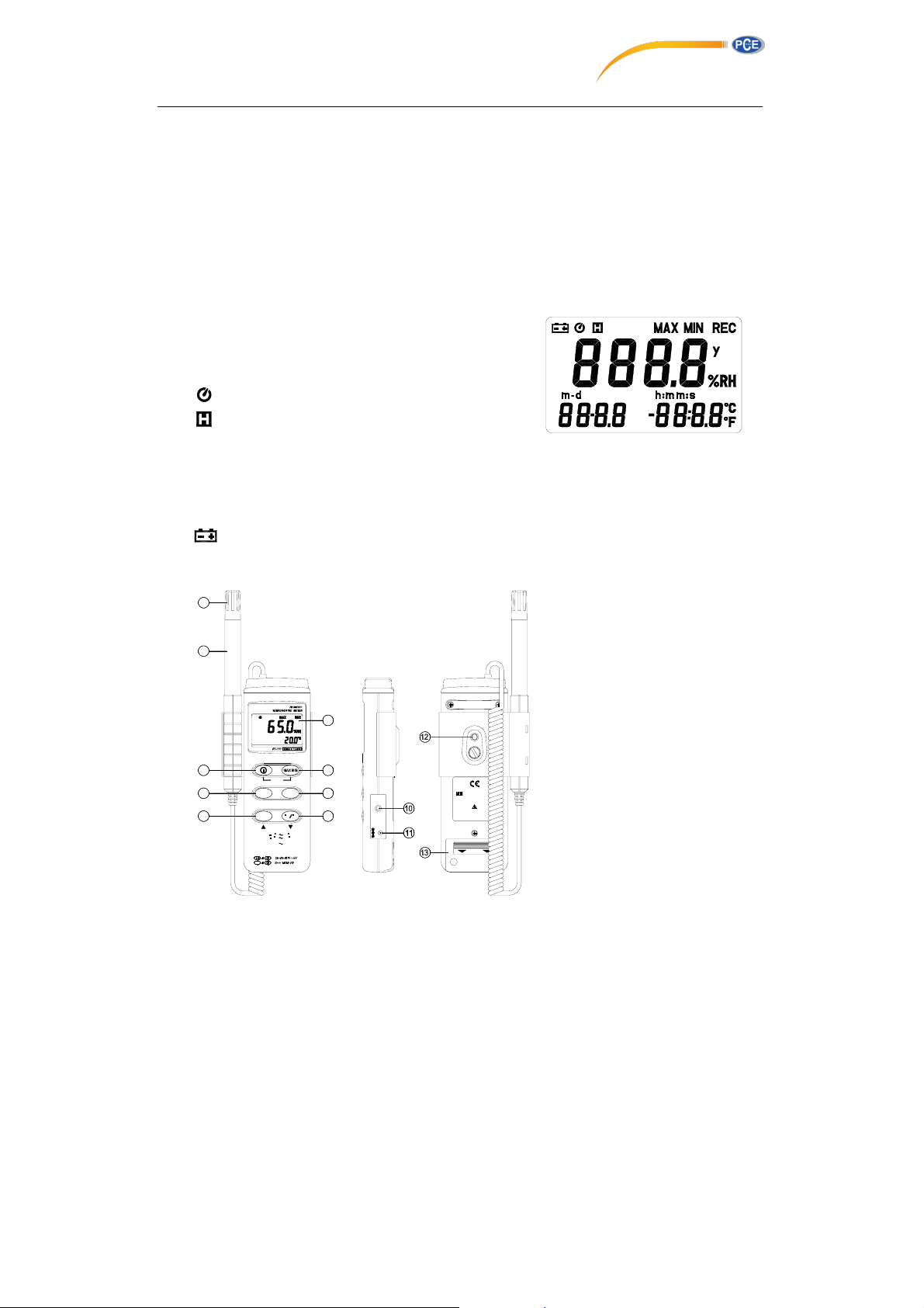
IV. Symbol Definition and Button Location:
°C°F : Centigrade and Fahrenheit indication.
%RH
: Relative Humidity indication.
MAX :
The Maximum value is now being displayed
MIN
: The Minimum value is now being displayed
: This indicates auto power off is enabled.
: This indicates that the display data is being held.
m-d
: month and day
h:m : hour and minute
m:s
: minute and second
Y
ear
: y
: The Battery is not suf
REC
: This indicates that the tester is recording. If it blinks, it indicates the memory is full.
ficient for proper operation.
1
2
3
4
5
6
SETUP
TIME
CLOCK
REC
TEMP:FC420
HUMIDITY: 0%R
POWER-UP O
PTIONS
REC
7
HOLD
8
INTV
C F
9
C
60
F140
H100
2
3
2
S
R
V
9
C
D
9V BATTERY
NEDA 1604 6F22
PLEASE READ
MANUAL FOR
OPEN
00
SAFE
Button Location
1
○ ,
Dust mask
2
○ ,
○ ,
○ ,
○ ,
○ ,
○ ,
○ ,
○ ,
○ ,
○ ,
probe
Sensor
3
LCD display
4
ON/OFF button
5
Time display button
6
Record button
7
MAX MIN function cont
8
HOLD button
9
°C, °F control button
10
Digital output connector (RS-232)
11
AC power adapter connector
:
rol button
Page 5
○ ,12 Tripod connector
13
Battery cabinet
○ ,
cover
V. Operatio
4.1 Power-Up
Press the
ON or OFF.
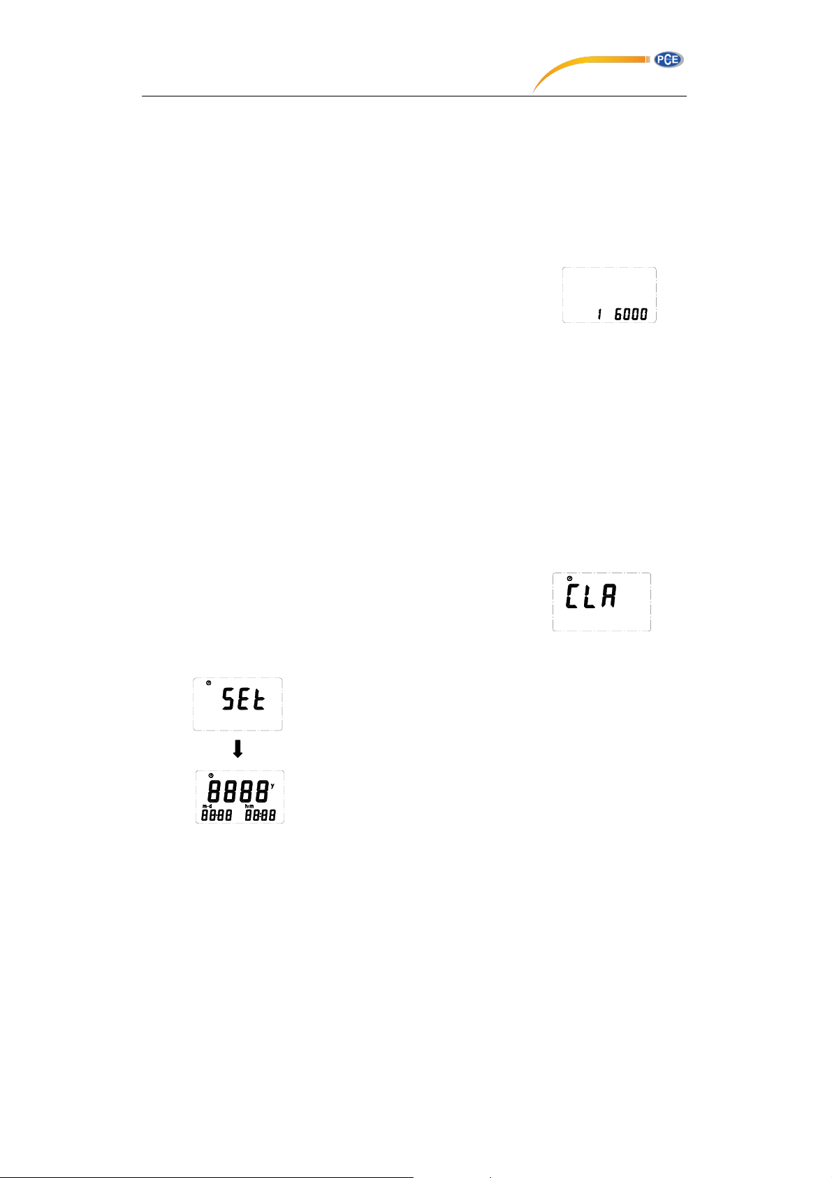
When the powered it on, the LCD will show how much memory
space is available to use.
For example: It indicates that there are 16,000 records memory space available.
4.2 Humidity and Temperature Measurement
For measurement, place the sensor probe in the test environment.
4.3 Selecting the Temperature Scale
When the meter is first powered on, the default scale setting is set at Celsius (°C) scale. The user
may change it to Fahrenheit (°F) by pressing “ °C/°F ” button and vice versa to Celsius. Next time
you power on, the scale setting will be the same as which when you powered off last time.
4.4 Data-Hold Operation
The user may hold the present reading and keep it on the display by pressing the “HOLD” button.
When the held data is no longer needed, one may release the data-hold operation by pressing
“HOLD” button again.
When the meter is under Data Hold operation, the "MAX MIN" and “ °C/°F ” button are disabled.
(when you press “ °C/°F ” and "MAX MIN" button in HOLD mode, there will be two continuous
beeps)
4.5 Data Logger
When pressing the "REC" button, the meter will start recording,
press the "REC" button again will stop recording, If you want to
clear the memory, power off the meter, then press and hold “REC”
button and then press power button, then release all buttons ,then
LCD will show "CLR" to clear the memory.
4.6 Clock Setup
n Instr
power button
uctions:
to t
urn the Humidity Temperature Meter
1: press and hold “MAX MIN” button and then power on the meter:
2: press “TIME”(clock):
3: press "REC" ▲ or "°C/°F" ▼ to increase or decrease number,
press “TIME”(clock) to adjust next item. The adjusting order is
Page 6
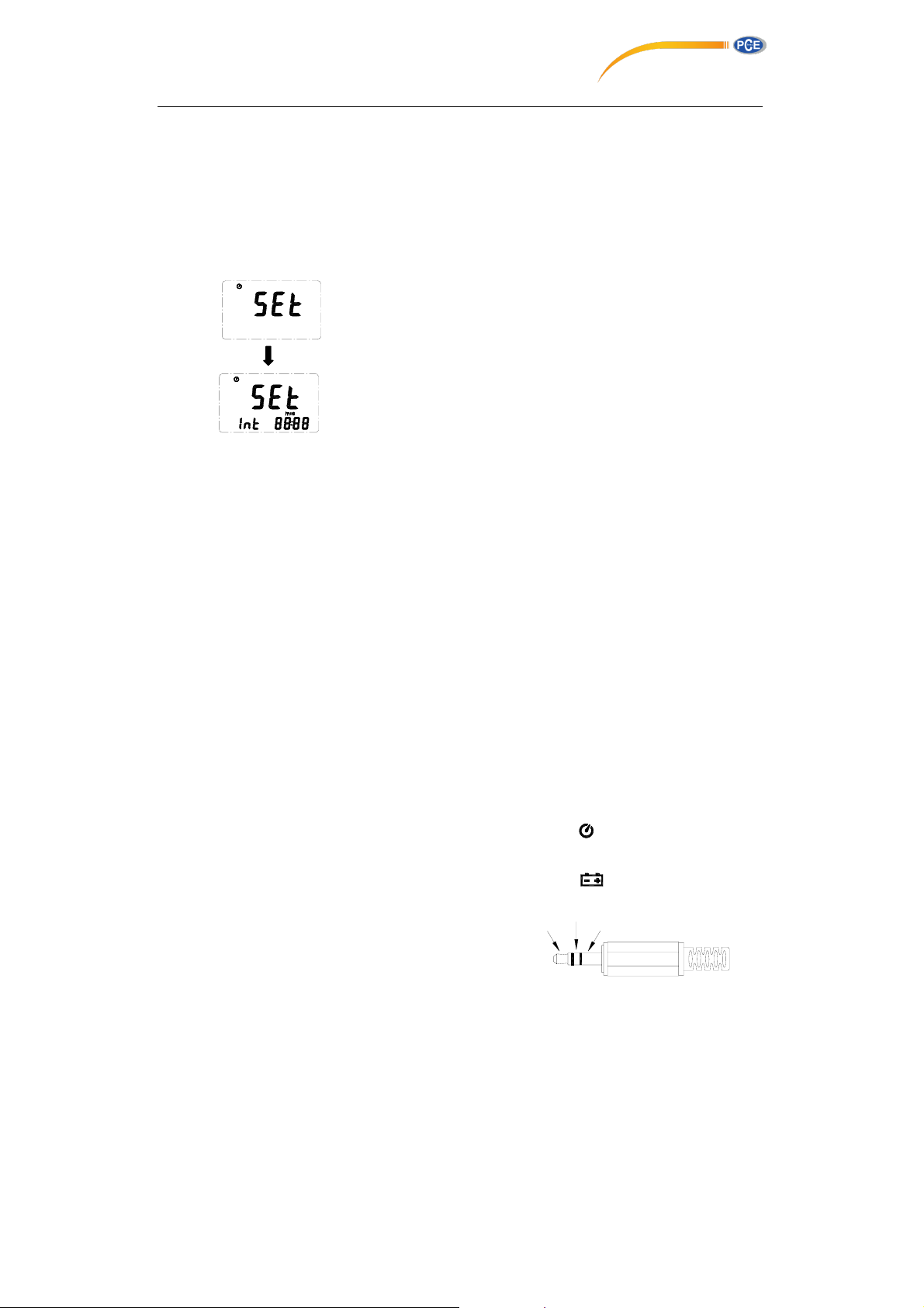
year→ month→ day→ hour→ minute, then press “TIME” (cloc
finish adjusting. If you want abort during a setup process, press
power button to cancel.
4.7 Recording Interval Setup :
1: press and hold “MAX MIN” button and then power on the meter:
2: press “HOLD"(INTV)
3: press "REC" ▲ or "°C/°F" ▼ to increase or decrease number,
press “HOLD" (INTV) to adjust next item, then press “HOLD” (INTV)
to finish. If you want abort during a setup process, press power
button to cancel.
4.8 Time Operation:
When pressing the “TIME” button, the LCD will display time , it will show year on top of the LCD,
show month and day on the left bottom of the LCD, show hour and minute on the right bottom of
the LCD. Press "TIME" button or any other button to exit this mode. This operation will not interrupt
the recording and "MAX MIN" operation.
4.9 MAX/MIN Operation:
When pressing the "MAX MIN" button the meter will enter the MAX/MIN mode. Under this mode the
maximum value / minimum value is kept in the memory simultaneously and updated with every new
data point.
When the MAX symbol is display, the Maximum is shown on the display.
Press "MAX MIN" again, then the MIN symbol is on the display and the minimum reading is
displayed.
Press "MAX MIN" again, MAX, and MIN will blink together. This means that all data is updated in the
memory and the reading is the present temperature.
One may press "MAX MIN" to circulate the display mode among these options.
When the meter is under "MAX MIN" operation, “ °C/°F ” button are disabled.(when you press
“ °C/°F ” button in "MAX MIN" mode, there will be two continuous beep)
To exit the MAX/MIN mode, one may press and hold "MAX MIN" for two seconds.
4.10 Auto Power Off:
By default, when the meter is powered on, it is under auto power off mode. The meter will power
itself off after 30 minutes if no key operation and no RS232 communication and no recording.
Combination at power on can disable auto power off.
One may press and hold “HOLD” button and then power on the meter and there will be two
successive beeps to indicate that auto power off is disabled and the will not show up.
4.11 Low Battery Condition
When the battery voltage is under proper operation requirement, the symbol will show on the
LCD and the battery need to be replaced with new one.
4.12 Digital Output:
The Digital Output is a 9600bps N 81 serial interface.
TX
RX
GND
k) to
Page 7
VI. Setup TestLink (Humidity DataLogger)—RS232 interface software:
y The TestLink package c
1.One setup CD.
2.Custom designed RS232 cable for TestLink.
y System Required:
Windows 98/ NT 4.0/ NT2000/ XP.
y Minimum Hardware Required:
486-100 MHz PC compatible, 16 MB RAM ;
At least 5 MB hard disk space available to install TestLink program. Recommended display
resolution is 800X600.
y Install TestLink:
1.We recommend close all other application before installing TestLink.
2.Insert the TestLink CD-ROM into your CD drive. The TestLink installer should start
automatically. If it does not, you can start it by running SETUP.EXE from the root drive of the
CD-ROM.
3.When installation is complete, it will copy TestLink.exe(executable file) and help file to your
hard disk(default is c:\program files\ TestLink)
4.For other operation instruction, please refer to the on-line help while executing TestLink.
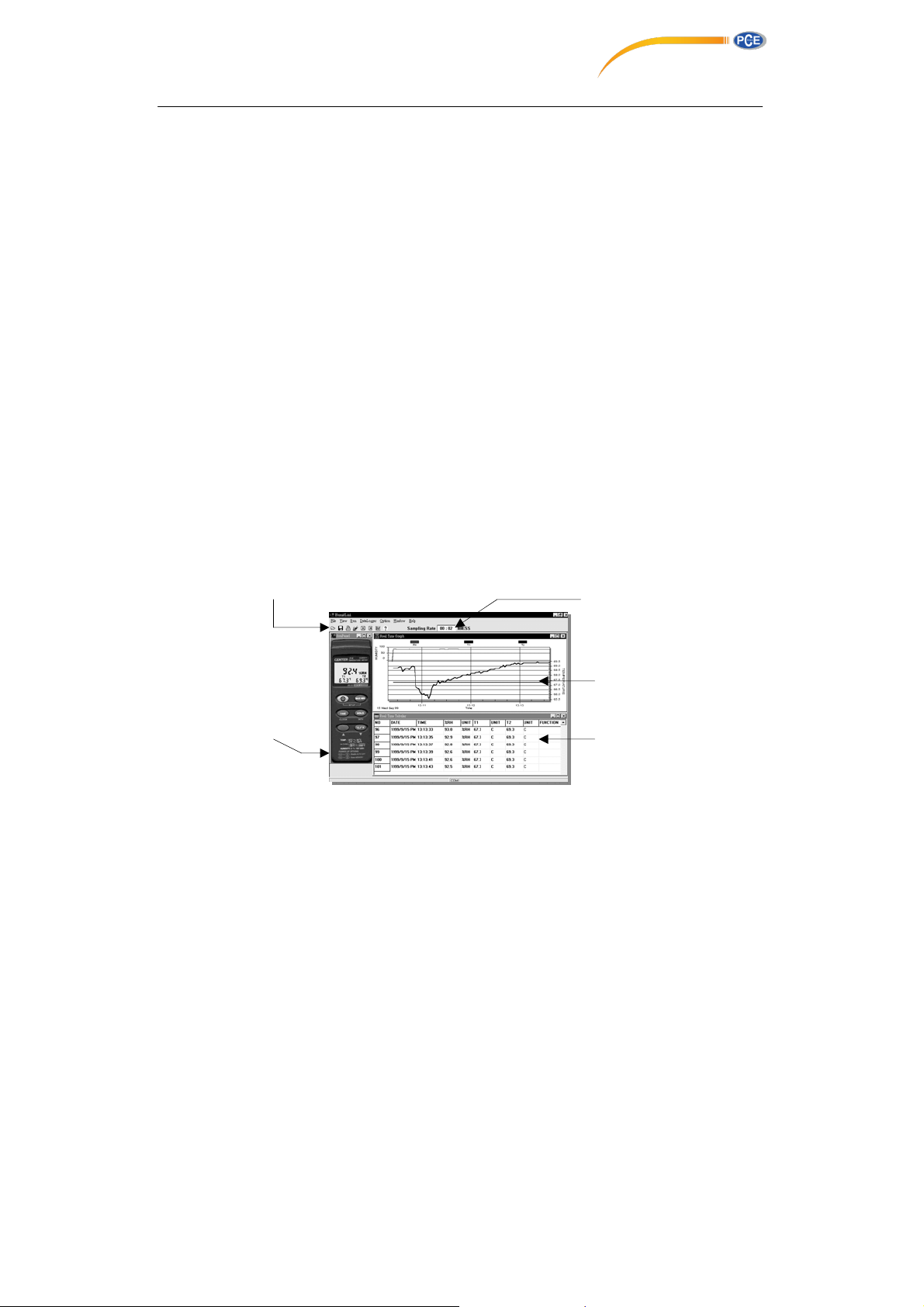
5-1. Run TestLink
Select TestLink form “START” of Windows, figure 5.1 will show
Menu and Tool Bar
Bi-dir
ection Control Panel
Figure 5.1
ontains:
Real Time Data Sa
Real Time Graph
Real Time T abular
mpling Rate
Page 8
Data Sets
Graph
Tabular
5-2. Real Time Tabular and Real
Select Run from menu or press from the tool bar to begin real time data collection from
humidity meter.
You can change the data interval by editing the sampling rate box on the right hand side of tool
bar (see figure 5.1).
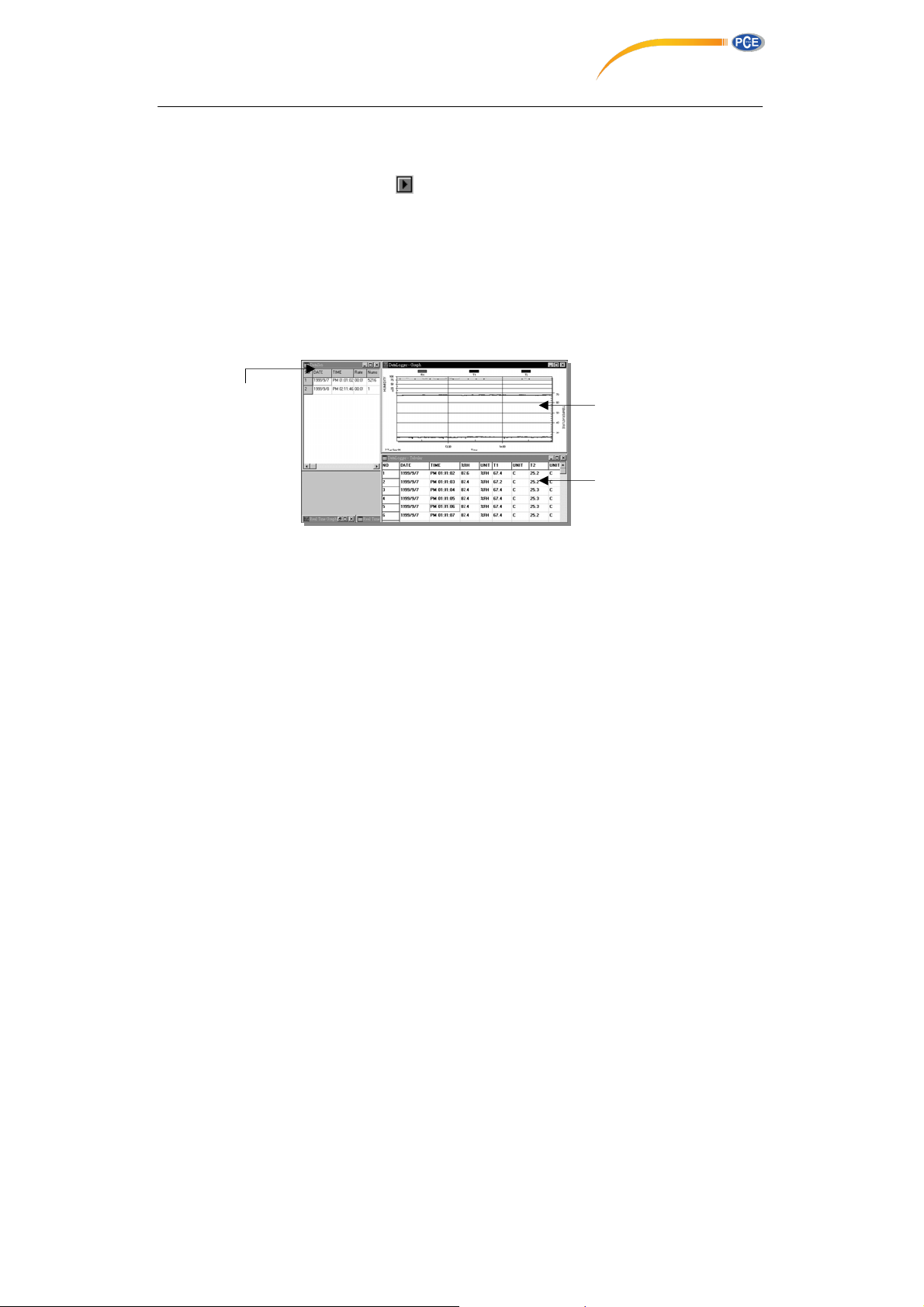
5-3. DataLogger
Select DataLogger from menu to load recorded data for humidity meter. There will be a progress
bar showing how many bytes should be loaded and how many bytes have been received. When
data is loaded successfully, there will be three new window show up. (see 5-2)
Time Graph.
Data Sets Window – Display how
data set (start date, start time, recording rate and data length), and you can click at any data set to
choose the set for graph and tabular Window.
5-4. For other operation instruction, please refer to the on-line help while executing TestLink.
many data sets were loaded and the detail information for each
NOTE: "This instrument doesn’t have ATEX protection
, so it should not be used in
potentially explosive atmospheres (powder, flammable gases)."
10
Graph
Tabular
 Loading...