

Page 1
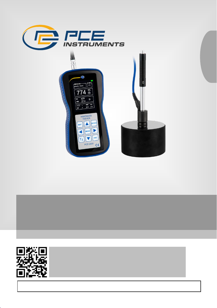
PCE-2900 Leeb Hardness Tester
User Manual
User manuals in various languages (français,
italiano, español, português, nederlands, türk, polski,
русский, 中文) can be found by using our
product search on: www.pce-instruments.com
Last change: 4 September 2024
v1.1
English
Page 2

© PCE Instruments
Contents
1 Safety notes ........................................................................................... 1
2 Introduction ........................................................................................... 2
3 Features ................................................................................................. 2
4 Technical specifications ...................................................................... 2
5 Measuring principle .............................................................................. 3
6 Standard package and optional accessories ..................................... 4
7 Device description ................................................................................ 4
8 Technical characteristics ..................................................................... 7
8.1 Characteristics of the test surface .................................................................................... 7
8.2 Specimen fixation ............................................................................................................. 7
9 Testing the accuracy ............................................................................ 8
10 Getting started ....................................................................................... 8
10.1 Assembly ......................................................................................................................... 8
10.2 Preparation ...................................................................................................................... 8
10.3 Load ................................................................................................................................. 8
11 Measurement ......................................................................................... 8
12 Test results representation .................................................................. 9
13 Menu navigation .................................................................................... 9
13.1 Impact direction ................................................................................................................ 9
13.2 Number of measurements to calculate average ...............................................................10
13.3 Material selection ............................................................................................................11
13.4 Probe type .......................................................................................................................12
13.5 Hardness scale selection.................................................................................................13
14 Instrument setup ................................................................................. 14
14.1 Display settings ...............................................................................................................14
14.2 Version ............................................................................................................................15
15 Data processing .................................................................................. 15
15.1 Data storage data via USB connection with an external USB data medium .....................16
15.2 Data storage and transfer via WiFi ..................................................................................17
Page 3

© PCE Instruments
16 Data/documents processing .............................................................. 18
17 Calibration ........................................................................................... 19
18 Maintenance and repair ...................................................................... 20
18.1 Battery replacement ........................................................................................................20
18.2 Troubleshooting ..............................................................................................................20
18.3 Environmental requirements ............................................................................................20
19 Charts ................................................................................................... 21
19.1 Chart 2 ................................ ................................................................ ............................21
19.2 Chart 3 ................................ ................................................................ ............................21
19.3 Chart 4 ................................ ................................................................ ............................22
20 Contact ................................................................................................. 23
21 Disposal ............................................................................................... 23
Page 4

© PCE Instruments
1
1 Safety notes
Please read this manual carefully and completely before you use the device for the first time. The
device may only be used by qualified personnel and repaired by PCE Instruments personnel.
Damage or injuries caused by non-observance of the manual are excluded from our liability and
not covered by our warranty.
• The device must only be used as described in this instruction manual. If used otherwise,
this can cause dangerous situations for the user and damage to the meter.
• The instrument may only be used if the environmental conditions (temperature, relative
humidity, …) are within the ranges stated in the technical specifications. Do not expose
the device to extreme temperatures, direct sunlight, extreme humidity or moisture.
• Do not expose the device to shocks or strong vibrations.
• The case should only be opened by qualified PCE Instruments personnel.
• Never use the instrument when your hands are wet.
• You must not make any technical changes to the device.
• The appliance should only be cleaned with a damp cloth. Use only pH-neutral cleaner,
no abrasives or solvents.
• The device must only be used with accessories from PCE Instruments or equivalent.
• Before each use, inspect the case for visible damage. If any damage is visible, do not
use the device.
• Do not use the instrument in explosive atmospheres.
• The measurement range as stated in the specifications must not be exceeded under
any circumstances.
• Non-observance of the safety notes can cause damage to the device and injuries to
the user.
We do not assume liability for printing errors or any other mistakes in this manual.
We expressly point to our general guarantee terms which can be found in our general terms of
business.
Page 5
© PCE Instruments
2
2 Introduction
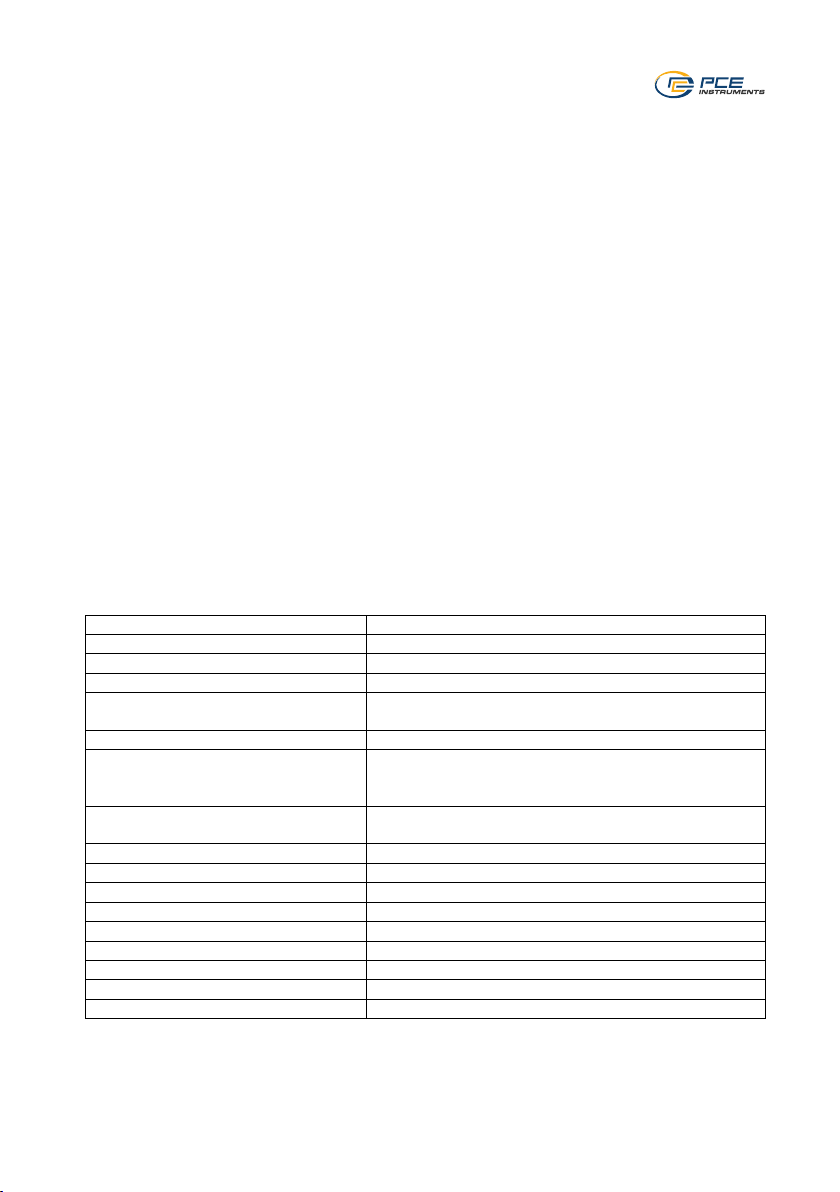
The PCE-2900 portable hardness tester enables quick and convenient on-site hardness testing
according to the Leeb principle.
The PCE-2900 is an advanced tester with a menu in English or German, with a high memory
capacity, a WiFi port (function will be available soon), a USB port, a long battery life (>50 h in
standby mode), etc.
The meter automatically shows the different hardness scales (HRC, HRB, HV, HB, HS) in the
display during the measurement.
The PCE-2900 has a low energy consumption, enabling the user to carry out continuous on-site
measurements.
The user manual should be read completely before first use.
3 Features
- Portable hand-held device, weight: 350 g
- Measurement possible in any position
- High accuracy of ±0.5 %
- Wide measurement range
- For metals
4 Technical specifications
Measuring range
170 ... 960 HLD
Reproducibility
± 6 HLD
Impactor
Type D
Measuring direction
360°
Adjustable scales
Leeb, Brinell, Rockwell A, Rockwell B, Rockwell C,
Vickers, Shore
Surface quality Ra of the workpiece
2 µm
Minimum weight of the workpiece
Direct measurement: 5 kg / 11 lbs
Tied measurement: 2 ... 5 kg / 4.4 ... 11 lbs
With coupling gel: 0.05 ... 2 kg / 0.1 ... 4.4 lbs
Minimum thickness of the workpiece
Direct measurement: > 5mm / > 0.19 in
With coupling gel: 0.8 ... 5 mm / 0.03 ... 0.19 in
Display
Colour LCD
Internal measured value memory
600 records in 6 files
Interface
USB, WiFi
Power supply
2 x 1.5V AA batteries
Operating time
ca. 50 hours
Operating conditions
10 ... 50°C / 50 ... 122°F max. 90% RH
Storage conditions
-30 ... 60°C / -22 ... 140°F max. 90% RH
Dimensions
160 x 80 x 35 mm / 6.3 x 3.1 x 1.3 in
Weight
350 g / < 1 lb
Page 6
© PCE Instruments
3
5 Measuring principle
Hardness measurement, rebound procedure (Leeb)
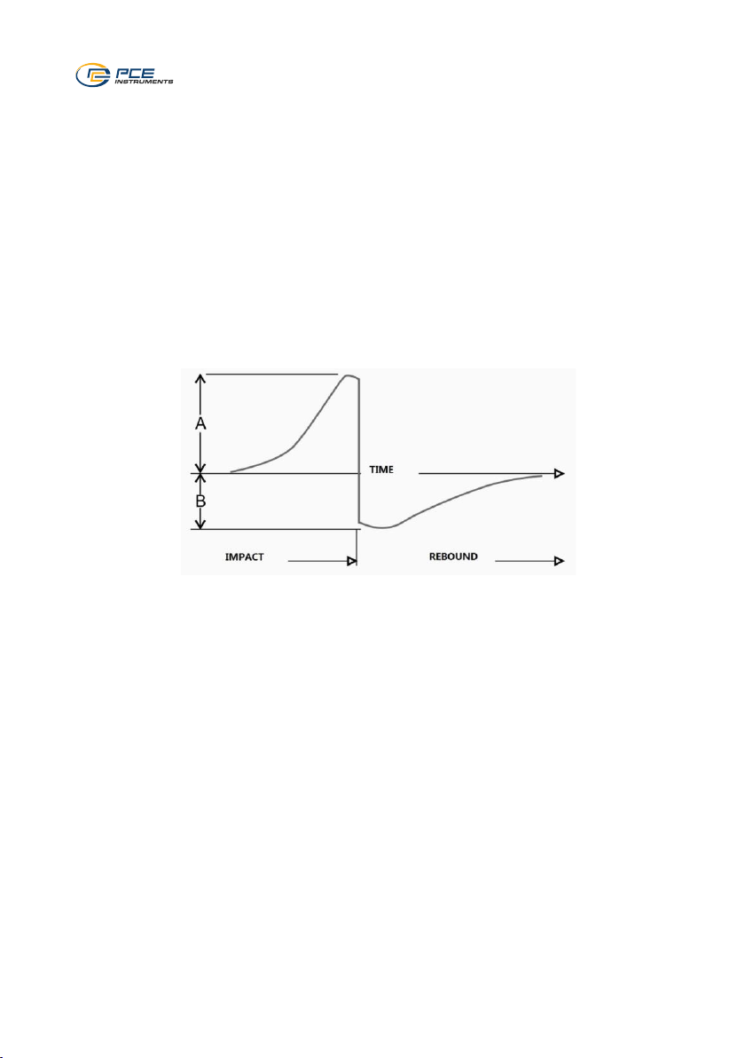
The rebound procedure is a dynamic hardness test procedure. Portable hardness testers such
as the PCE-2900 work according to this principle. A spring force propels an impact body (a carbide
ball) against the surface of the material to be tested.
The decrease in velocity between the impact and the rebound of the impact body serves as the
measuring parameter. After a calibration and in consideration of the influence of the mass and
the surface characteristics of the test material, the decrease in velocity is directly linked to the
hardness.
HL = 1000×VB/ VA
HL = Leeb hardness
VB = Rebound velocity
VA = Impact velocity of impact body
Diagram:
Page 7
© PCE Instruments
4
6 Standard package and optional accessories
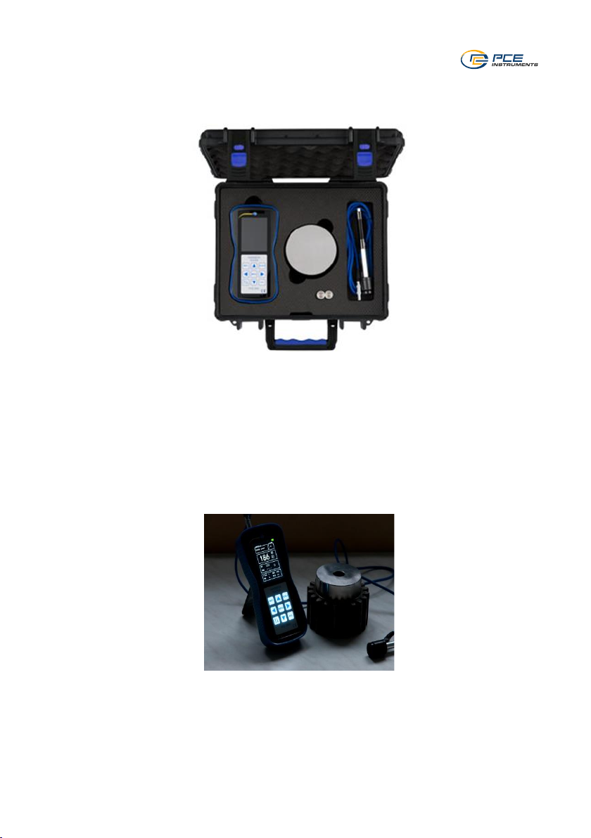
1 x hardness tester PCE-2900, 1 x Impact device type D with cable, 1 x test block, 2 x 1.5 V AA
batteries, 1 x user manual, 1 x carrying case
Optional: ISO calibration certificate
A certification according to DIN ISO includes a laboratory calibration incl. certificate with all
measured values. This can be purchased directly with your PCE-2900 hardness tester and as a
re-calibration every year.
7 Device description
7.1.1 Display with touch pad
Page 8
© PCE Instruments
5
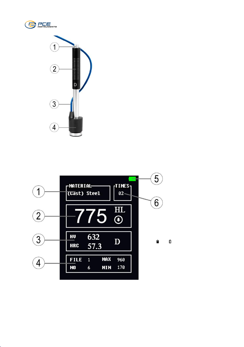
7.1.2 Probe
7.1.3 Display main menu
- 1. Trigger button
- 2. Test body
- 3. Test cable
- 4. Test tip
- 1. Material
- 2. Hardness scale
- 3. Reading information
- 4. File no., memory item
- 5. Battery level,
- ok, charging
6. No. of measurements to
calculate average
Page 9
© PCE Instruments
6
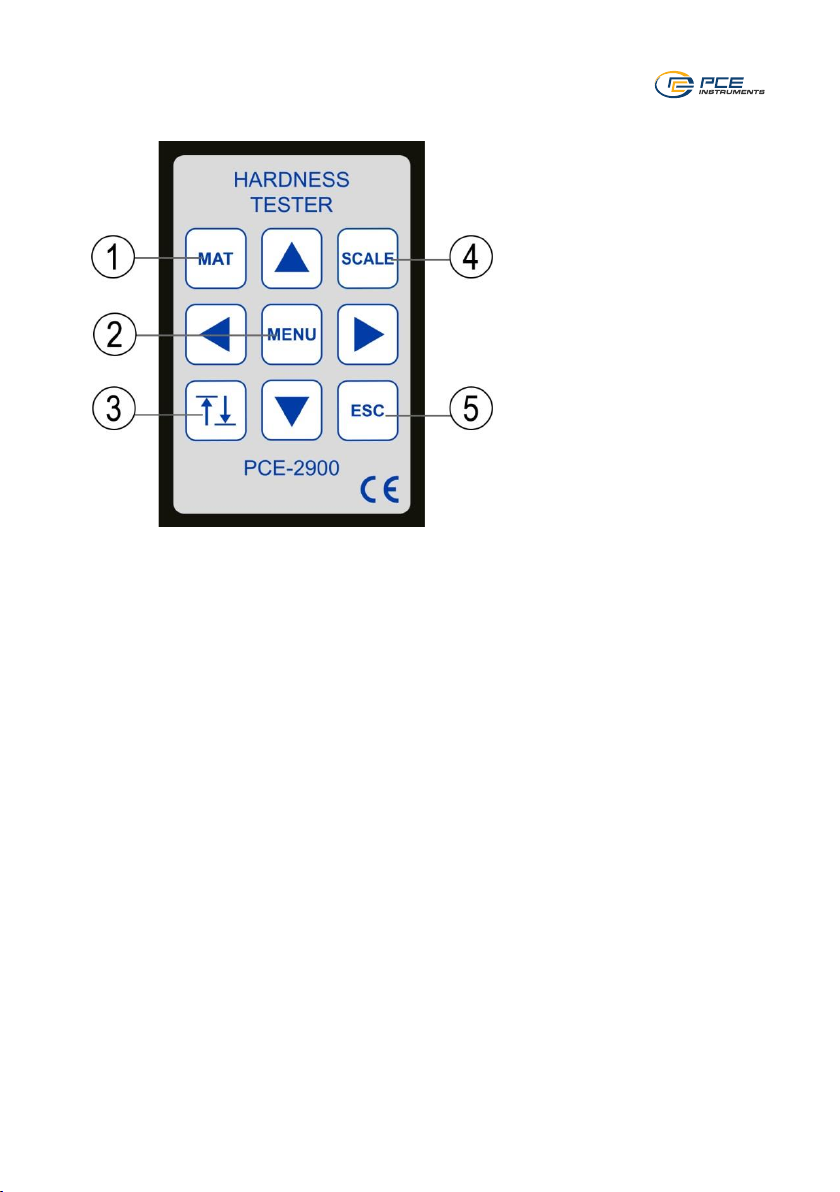
7.1.4 Keys
- 1. Material selection
- 2. Menu
- 3. Calibration
- 4. Hardness scale setting
- 5. ESC
© PCE Instruments
Page 10
7
8 Technical characteristics
8.1 Characteristics of the test surface
The specimen surface shall comply with the relevant requirements in chart 2.
Avoid excessive heat or cold treatments to the surface.
• The roughness of the specimen surface will affect the measurement accuracy.
Therefore, the test specimen surface must keep metallic luster and be smooth and
free from oil.
• A flat and even surface will bring the best results.
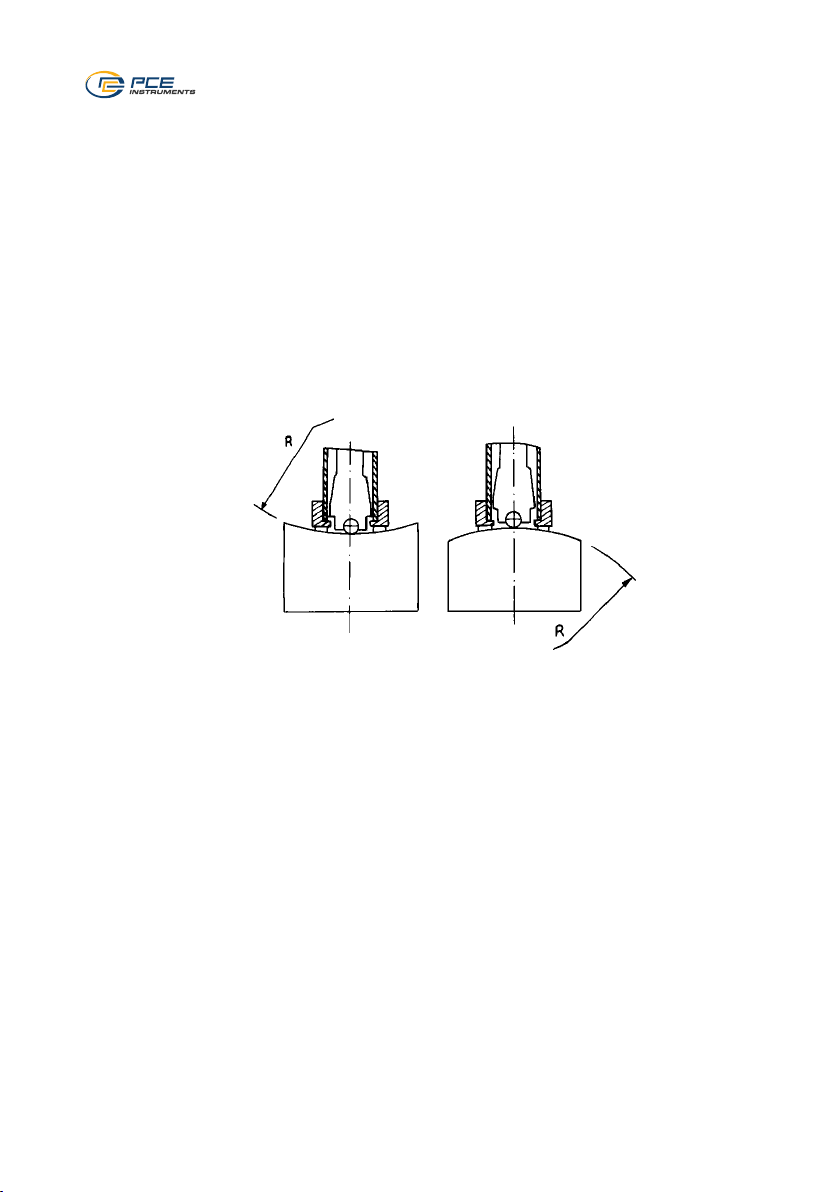
• When the curvature R of the measured surface is less than 30 mm, the standard
support ring should be replaced by a smaller support ring or by specially shaped
support rings.
8.2 Specimen fixation
For heavy samples, no fixation is needed.
Medium-sized specimen must be placed on a flat, hard and solid surface, in an absolutely stable
way without any room for movement. The sample should fulfil the minimum thickness of the
according to chart 2.
For samples with surface hardened layer, the hardening layer depth must be as specified in
chart 2.
Lightweight samples must be tightly coupled with a supporting body with some coupling agent.
The two coupling surfaces must be smooth.
The probe must be rectangular to the sample.
If the sample is a big plate, pole or bending part, it must be fixed accordingly. If this is not
observed, deformations, instability and decreased accuracy can occur.
The sample should be less than 30 gauss magnetic.
Page 11

© PCE Instruments
8
9 Testing the accuracy
Test the calibration of the hardness tester by using some hardness blocks with a known hardness.
The value of the test blocks and the repeatability should be within the range according to chart 2
and 3.
Note
The hardness blocks used should be standard Leeb hardness blocks. Each hardness block
should be tested 5 times.
If the mean value deviates too much from the hardness value (HLD, Leeb) specified on the test
block, you must calibrate the gauge by using the calibration function in the menu.
10 Getting started
10.1 Assembly
Attach the test cable to the test tip by inserting the 3-pole plug of the cable into the jack of the test
tip. Then insert the test cable into the jack at the front of the PCE-2900 hardness tester.
10.2 Preparation
On the front side of the meter, next to the probe jack, you can find the On/Off button. Push this
button briefly to turn on/off. The PCE-2900 will automatically power off after approx. 5 minutes of
inactivity.
10.3 Load
Push down the black plastic sleeve in the direction of the test tip until you hear a clicking sound,
meaning that it snaps in. The sleeve will then move back up. The test tip is now loaded.
Before starting a measurement, check if the trigger mechanism works by applying the trigger
button without placing the test tip on the test surface.
11 Measurement
Place the test tip on the test surface rectangularly. The support ring must lay evenly on the test
surface. Push the trigger button on the upper side of the impact device, in a similar way as you
would use a ball pen. You can then read the measured value on the display and load the test tip
again. Each sample must be tested 5 times. The deviation of the mean value should not exceed
15 HL.
The permissible distance between any two indentations or any indentation to the edge of the
can be found in chart 1.
For a specific material, to transfer Leeb hardness values accurately into other hardness scales,
you must carry out a contrast test to get the corresponding conversion relationship.
The contrast test must be carried out using an accredited Leeb hardness tester of the
corresponding hardness scale, tested on the same sample. Five points per scale must be tested
to set up the hardness diagram for comparison which must include at least three sets of data.
Chart 1
Distance between the two
indentation centers
Distance between Indentation center and the
sample edge ≥ ≥
3mm
5mm
Page 12
© PCE Instruments
9
12 Test results representation
Leeb hardness values are shown on the display. For example, 700HLD represents a D-type
impact device that has measured a Leeb hardness value of 700.
When Leeb hardness values are converted into other hardness scales, the abbreviation of the
hardness scale must be followed by the Leeb hardness abbreviation. For example, 400HV HLD
means that a measurement was made with a D-type impact device in line with the Leeb hardness
scale and the converted Vickers hardness value is 400.
13 Menu navigation
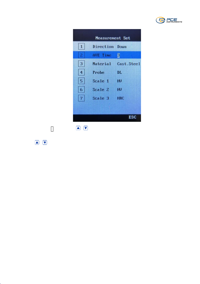
13.1 Impact direction
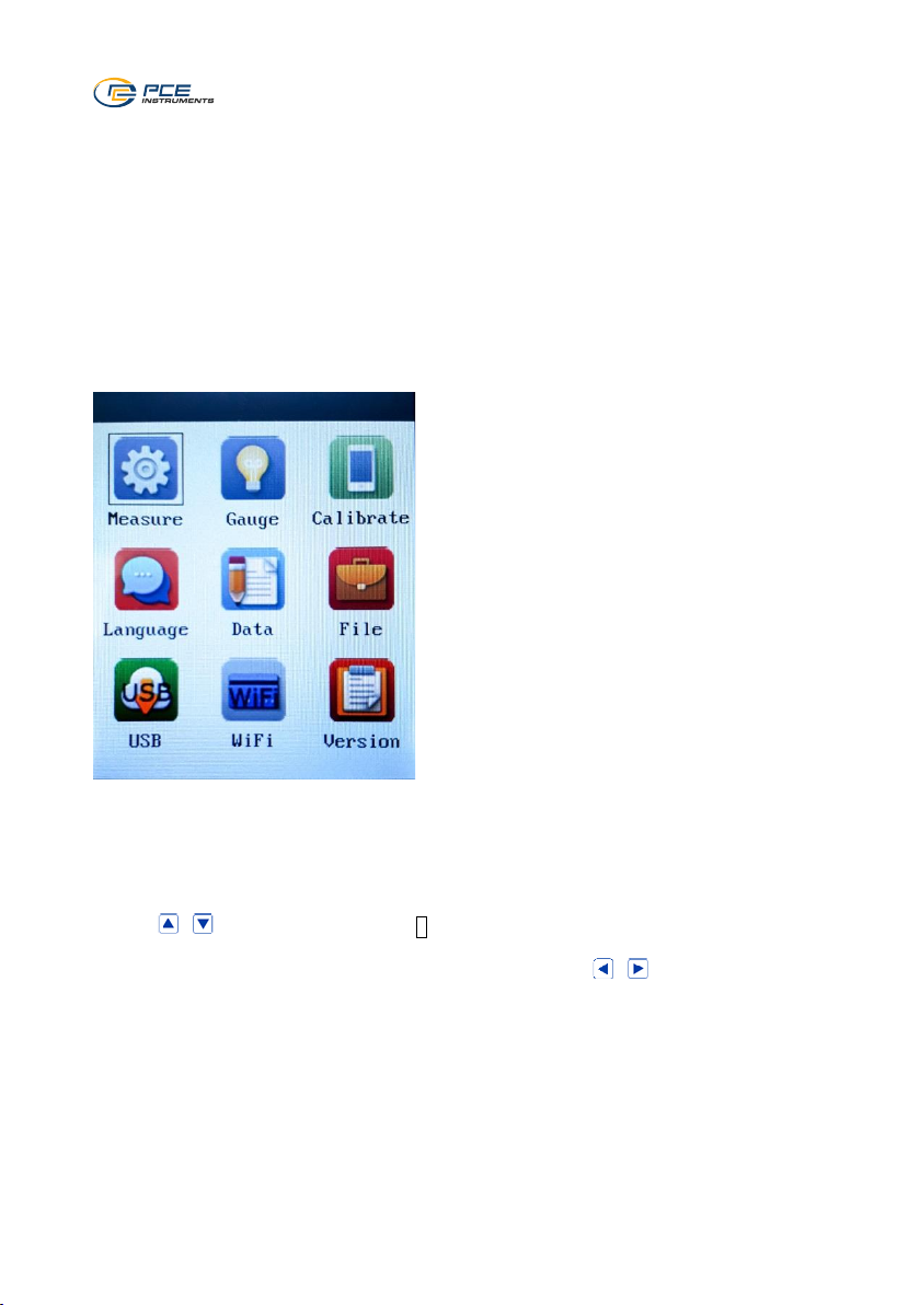
Press the Menu key.
Go to the menu item „Measure“.
Use the keys to select menu item 1.
Then select the impact direction for the measurement, using the keys.
You can choose from these options: +90°; -45°; 0°; +45°;-90°
Press the ESC key to leave the selection screen and go back to the last menu item.
- Press the Menu key.
- The virtual keypad will appear.
- Press the ESC key to return to the last
menu item.
Page 13
© PCE Instruments
10
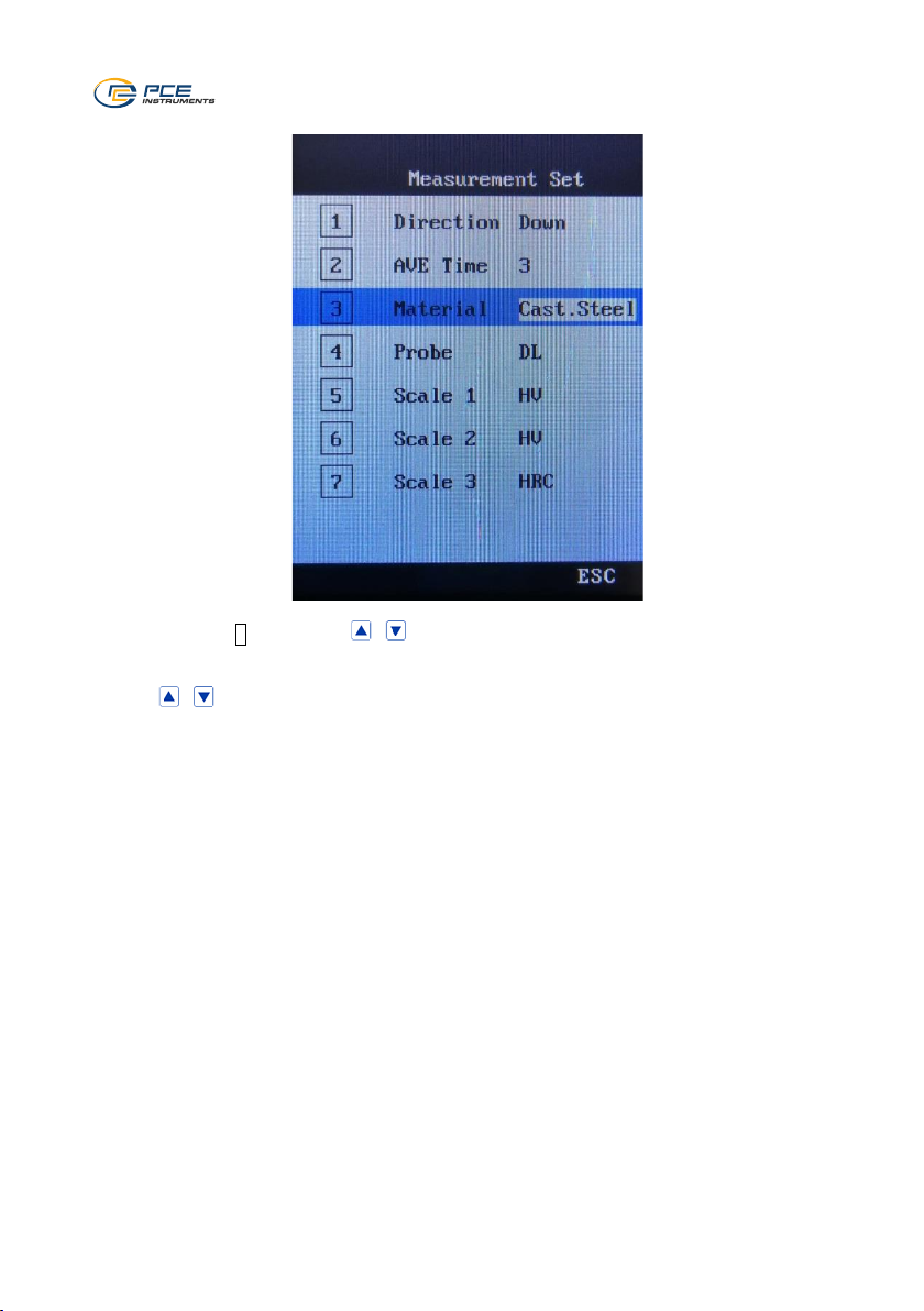
13.2 Number of measurements to calculate average
Select menu item 2 by using the keys.
Use the keys again to select the number of measurements to be used to calculate the
average value.
Leave the selection screen and go back to the previous menu item by pressing ESC.
Page 14
© PCE Instruments
11
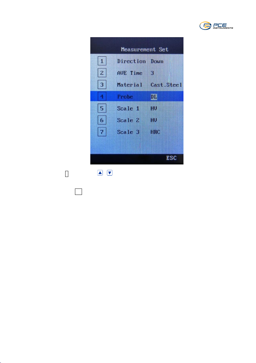
13.3 Material selection
Select menu item 3 by using the keys.
Use the keys again to select the material to be tested.
You can select one of these materials: CWT steel, stainless steel, grey cast iron, nodular cast
iron, cast aluminium, red brass, CU cast aluminium, copper
Leave the selection screen and go back to the previous menu item by pressing ESC.
Page 15
© PCE Instruments
12
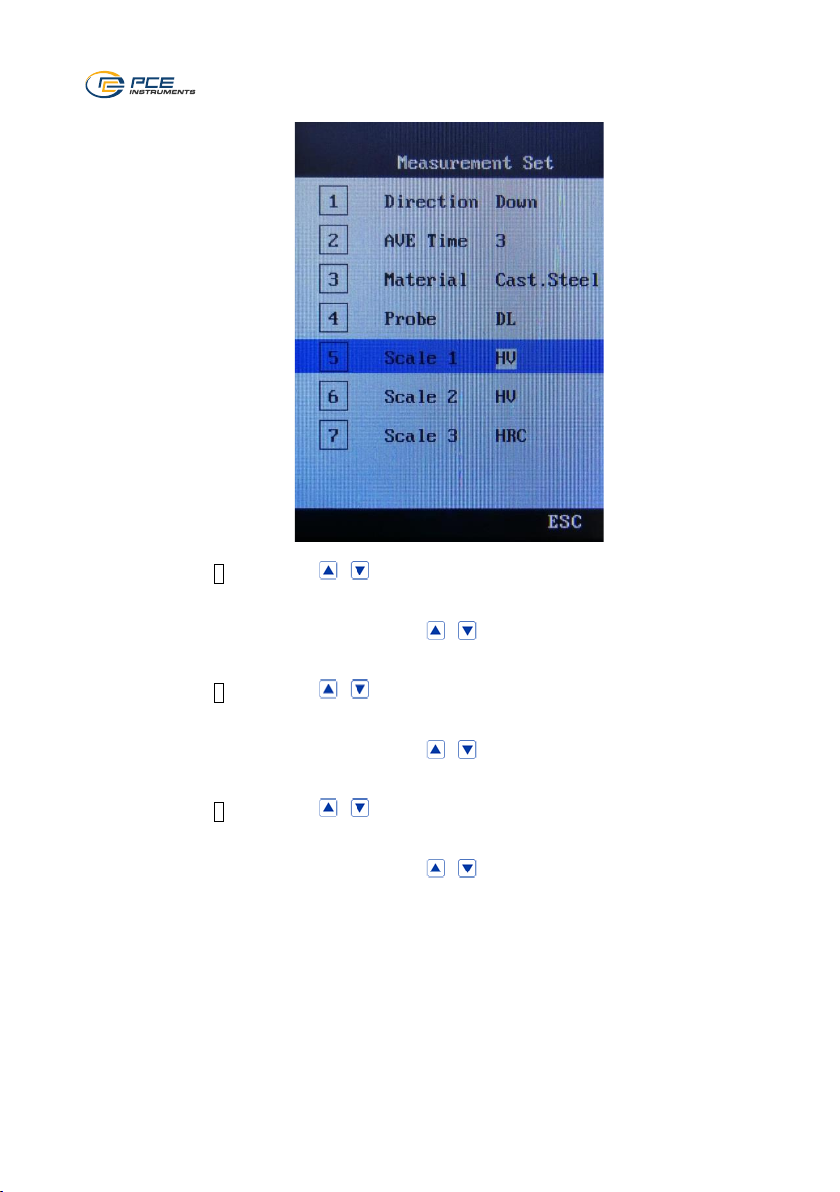
13.4 Probe type
Select menu item 4 by using the keys.
Select the probe type. DL is the standard value.
Leave the selection screen and go back to the previous menu item by pressing ESC.
Page 16
© PCE Instruments
13
13.5 Hardness scale selection
Select menu item 5 by using the keys.
Select the required hardness scale by using the keys.
Select menu item 6 by using the keys.
Select the required hardness scale by using the keys.
Select menu item 7 by using the keys.
Select the required hardness scale by using the keys.
In each menu item, you can select HL, HRA, HRB, HS, HRC, HB or HV.
Leave the selection screen and go back to the previous menu item by pressing ESC.
Page 17
© PCE Instruments
14
14 Instrument setup
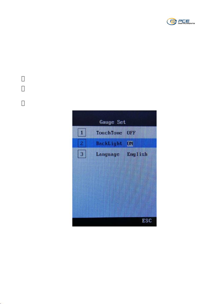
There are many display settings which the user can set according to their own demand.
14.1 Display settings
User the arrow keys to select the “Setup” menu and press the Menu key.
Use the arrow keys to make one of the following selections:
1 Touch tone on / off, confirm with the Menu key or go back with the ESC key.
2 Backlight on / off, confirm with the Menu key or go back with the ESC key.
Note: Use only in dark environments to keep energy consumption low.
3 Language: Chinese / English / German, confirm with the Menu key or go back with the ESC
key.
Page 18
© PCE Instruments
15
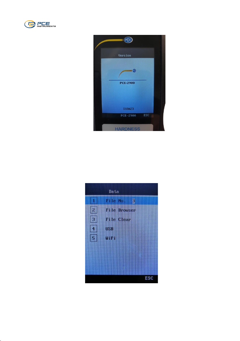
14.2 Version
This cannot be changed. Current version is shown here.
15 Data processing
The PCE-2900 has several functions like data saving, data browsing, data deletion, etc. The
data can be read out in two different ways as described below.
Page 19
© PCE Instruments
16
1. First possibility:
Data readout and storage on an external memory unit with a USB port (USB pen
drive).
The data can be transferred to a computer where they can be saved and
processed.
2. Second possibility (available soon):
Data can soon be read out and saved to a portable data management device via
WiFi. (The software must be properly installed)
15.1 Data storage data via USB connection with an external USB data medium
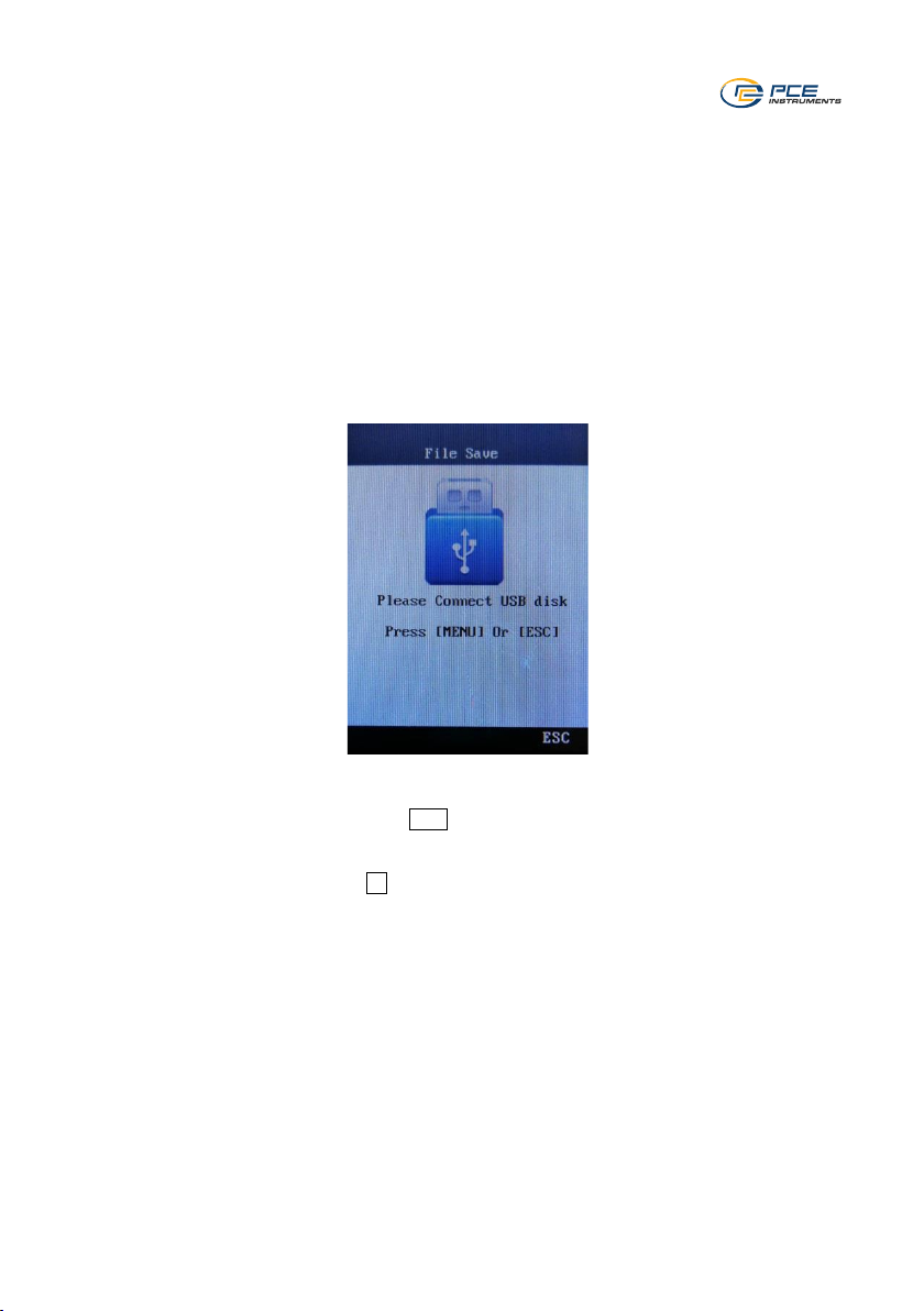
PCE-2900 can save date via U disk while please note the USB connection merely for U disk not
for PC connection.
• After turn on the tester, select USB by using the arrow keys.
• Connect the external USB data medium with your PCE-2900 and press the Menu key
to save the data to the USB data medium (USB pen drive).
• When the screen shows ok, you can disconnect the pen drive.
• Plug in the USB data medium into your PC or into any other data input and output
device to save and read out the data.
Page 20

© PCE Instruments
17
15.2 Data storage and transfer via WiFi
The PCE-2900 will soon be able to transmit data via WiFi. These data can be saved and read out
via portable data input and output devices.
1) Download the software to your Android device.
2) Switch on the PCE-2900 and navigate to the WIFI item in the menu.
3) Under WIFI, confirm that a connection is to be established.
4) In the settings now displayed, navigate to the Real Time item and turn it ON using the arrow
keys.
5) Then start the downloaded app on your Android device and click on "Connect" and "Wi-Fi
connection". You will be redirected to the Wi-Fi settings of your device.
6) Connect to the "cloud_Link" Wi-Fi.
7) As soon as the connection to the Wi-Fi has been established, open the app again and navigate
to the "Measure" item in the app.
8) The IP address and port of the device should now be displayed. You can now start your
measurements on your PCE-2900 and the measured values will be forwarded to your Android
device and displayed in real time.
Page 21
© PCE Instruments
18
16 Data/documents processing
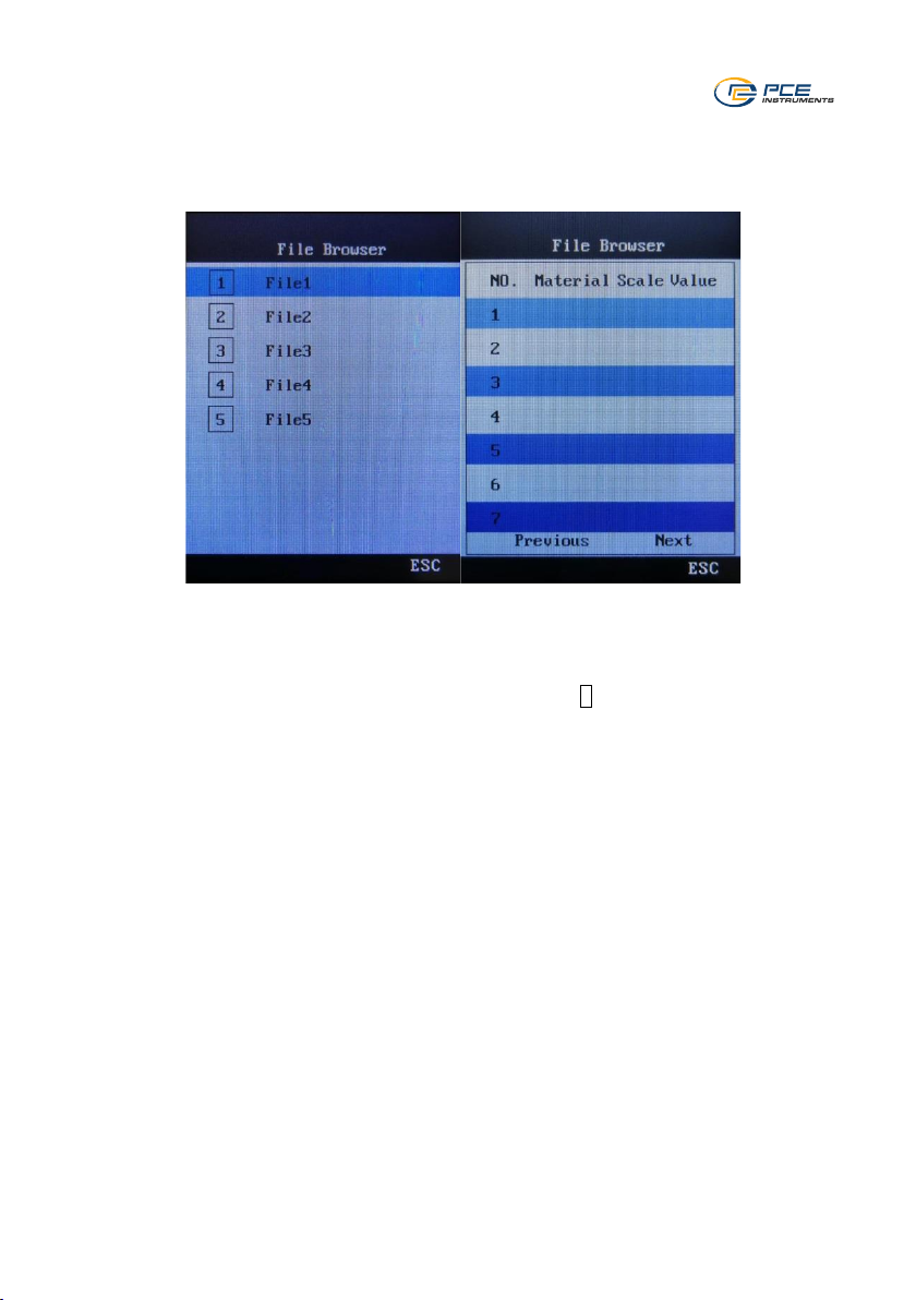
Use the arrow keys to select the menu “file”. Press the Menu key to confirm. Select the right file
(1-5) with the arrow keys.
• Select the file no. by using the arrow keys.
The max. possible file number is 5.
Confirm with the Menu key.
• Use the arrow keys to select the menu sub-item 2
Select “Browse file”. Confirm with the Menu key. Select one out of 28 memory
items using the arrow keys.
• Press the Menu key to delete memory items. The menu item “Delete file” will
appear. Select the files by means of the arrow keys and delete them with the
Menu key.
Page 22
© PCE Instruments
19
17 Calibration
When users operate the PCE-2900 for the first time or after a longer break, the meter must be
calibrated by using Leeb hardness block which comes with it.
There are several kinds of impact devices. When an impact device is calibrated, there is no
need to calibrate it again for the next use.
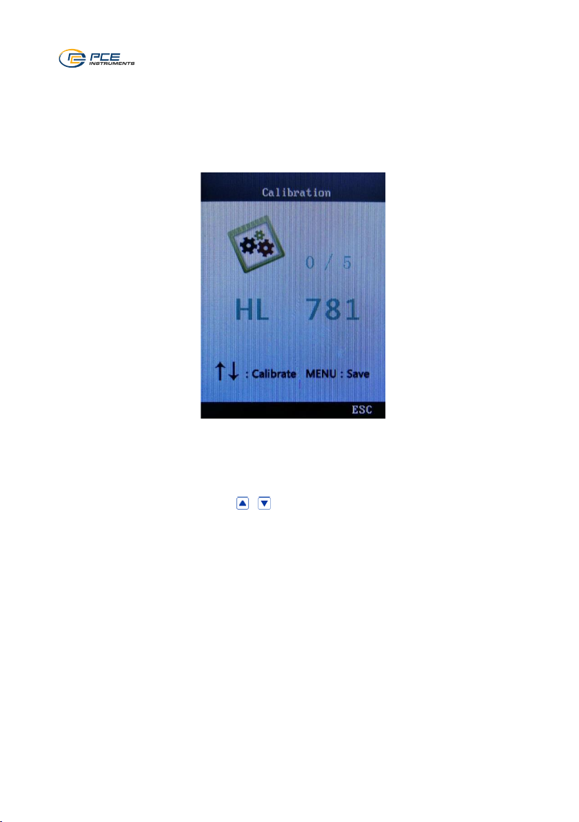
• Press the Menu key and select “Calibration” with the arrow keys.
• Press the Menu key to enter calibration mode.
• As described above, you must make 5 measurements on the test block to get the
average value which will be shown on the display.
• Press the arrow keys to compare the measured average value to the
hardness value on the test block. With the Menu key, you can complete and save
the calibration. The calibration tolerance is ±150HL.
Page 23

© PCE Instruments
20
18 Maintenance and repair
18.1 Battery replacement
The battery life is normally 3 years. If required, the battery can be replaced as follows:
• Switch off the device.
• Loosen the Philips-head screw at the bottom of the device near the stand.
Remove the battery compartment cover.
• Remove both batteries and insert two new AAA batteries, size M. Observe
correct polarity.
• Put the battery compartment cover back on and tighten the Philips-head screw.
• After the battery replacement, turn on the instrument to check whether it works
properly.
18.2 Troubleshooting
If any malfunctions occur, remove the batteries and put them back in to re-start the device. If the
problem persists, contact PCE Instruments, see contact details on the last page of this manual.
18.3 Environmental requirements
Avoid mechanical damage, heavy dust, humidity, strong magnetic fields, oil and grease pollution,
etc.
Page 24
© PCE Instruments
21
19 Charts
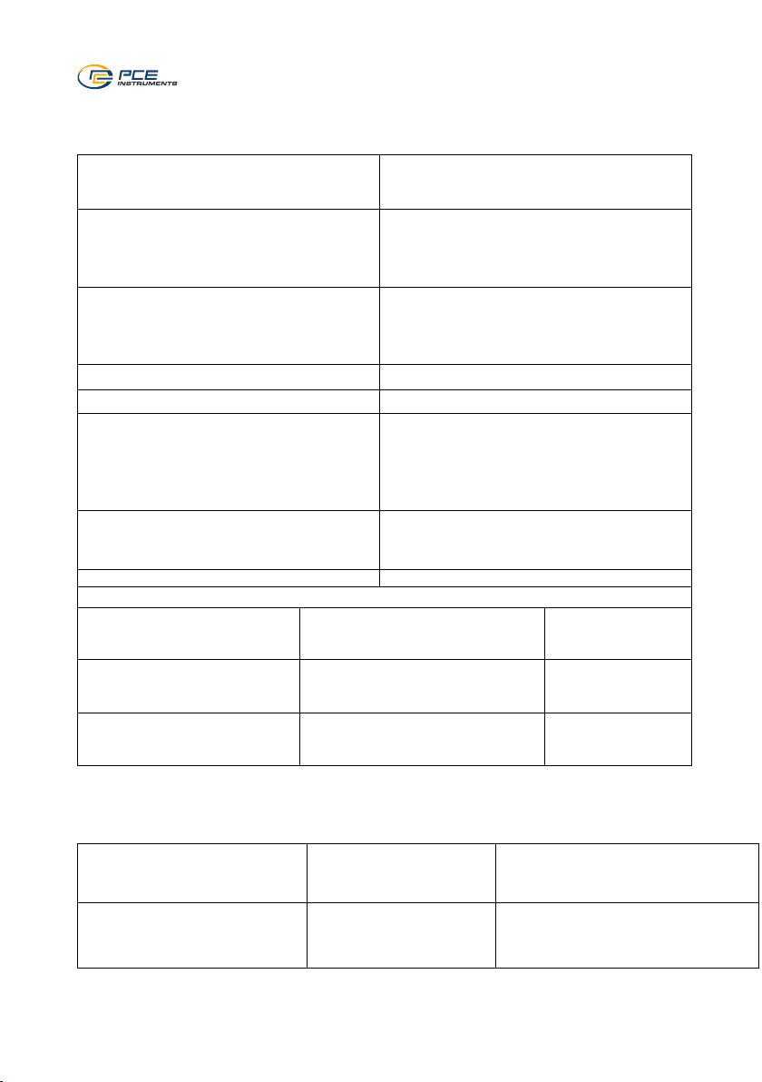
19.1 Chart 2
Impact energy
Impact weight
11 mJ
5.5 g
Ball hardness
Ball diameter
Ball material
1600 HV
3 mm
Tungsten carbide
Impact device diameter
Impact device length
Impact device weight
20 mm
147 mm
50 g
Hardness of test block
approx. 770 … 795 HLD
Roughness of block Ra
1.6 μm
Min. weight of block
Direct measurement
Measurement with support
Measurement with coupling
>5 kg
2~5 kg
0.05~2 kg
Min. hardness of block
Direct measurement
Measurement with coupling
>5 mm
≤5 mm
Min. depth
0.8 mm
Impact size of test tip
Hardness 300 HV
Impact diameter
Impact depth
0.54 mm
24 μm
Hardness 600 HV
Impact diameter
Impact depth
0.54 mm
17 μm
Hardness 800 HV
Impact diameter
Impact depth
0.35 mm
10 μm
Characteristics of the meter and of the measuring procedure
19.2 Chart 3
Standard hardness
Error value
Value repeatabliltity
760±30 HLD
530±40 HLD
±6 HLD
±10 HLD
6 HLD
10 HLD
Error values
Page 25
© PCE Instruments
22
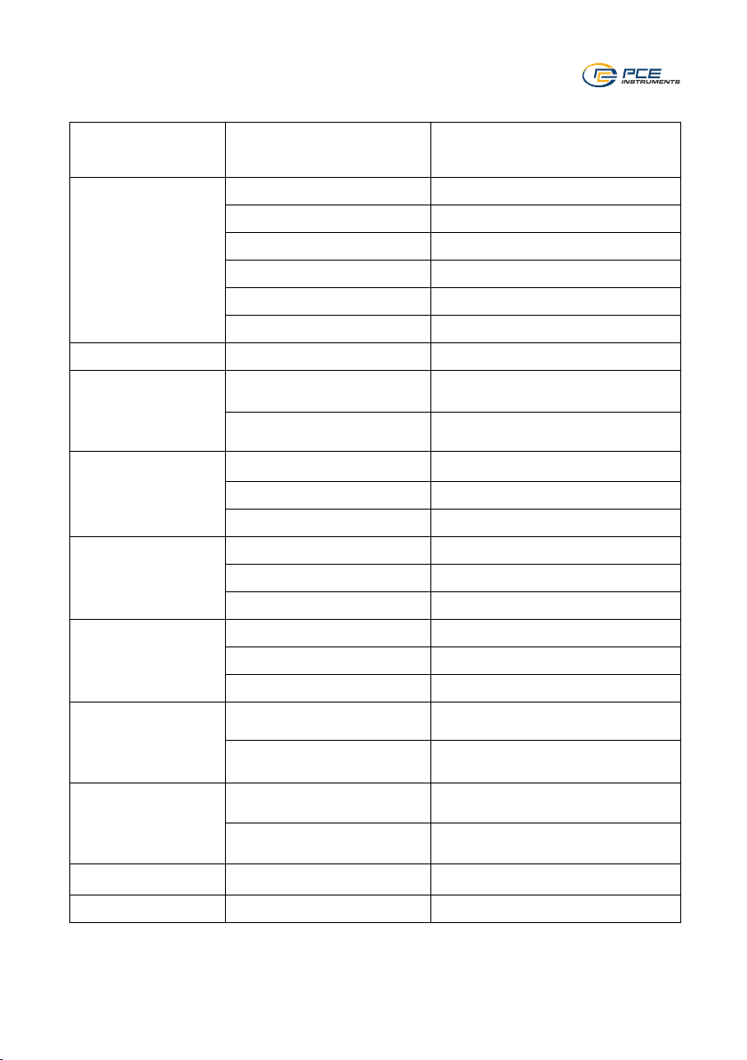
19.3 Chart 4
Material
Hardness Scale
D/DC
Steel and cast steel
HRC
17.9~68.5
HRB
59.6~99.6
HRA
59.1~85.8
HB
127~651
HV
83~976
HS
32.2~99.5
Steel
HB
143~650
CWT、ST
HRC
20.4~67.1
HV
80~898
Stainless steel
HRB
46.5~101.7
HB
85~655
HV
85~802
GC. IRON
HRC
HB
93~334
HV
NC、IRON
HRC HB
131~387
HV
C.ALUM
HB
19~164
HRB
23.8~84.6
BRASS
HB
40~173
HRB
13.5~95.3
BRONZE
HB
60~290
COPPER
HB
45~315
Page 26
© PCE Instruments
23
20 Contact
If you have any questions, suggestions or technical problems, please do not hesitate to contact
us. You will find the relevant contact information at the end of this user manual.
21 Disposal
For the disposal of batteries in the EU, the 2006/66/EC directive of the European Parliament
applies. Due to the contained pollutants, batteries must not be disposed of as household waste.
They must be given to collection points designed for that purpose.
In order to comply with the EU directive 2012/19/EU we take our devices back. We either re-use
them or give them to a recycling company which disposes of the devices in line with law.
For countries outside the EU, batteries and devices should be disposed of in accordance with
your local waste regulations.
If you have any questions, please contact PCE Instruments.
Page 27

© PCE Instruments
24
PCE Instruments contact information
Germany France Spain
PCE Deutschland GmbH PCE Instruments France EURL PCE Ibérica S.L.
Im Langel 26 23, rue de Strasbourg Calle Mula, 8
D-59872 Meschede 67250 Soultz-Sous-Forets 02500 Tobarra (Albacete)
Deutschland France España
Tel.: +49 (0) 2903 976 99 0 Téléphone: +33 (0) 972 3537 17 Tel. : +34 967 543 548
Fax: +49 (0) 2903 976 99 29 Numéro de fax: +33 (0) 972 3537 18 Fax: +34 967 543 542
[email protected] [email protected] [email protected]
www.pce-instruments.com/deutsch www.pce-instruments.com/french www.pce-instruments.com/espanol
United Kingdom Italy Turkey
PCE Instruments UK Ltd PCE Italia s.r.l. PCE Teknik Cihazları Ltd.Şti.
Trafford House Via Pesciatina 878 / B-Interno 6 Halkalı Merkez Mah.
Chester Rd, Old Trafford 55010 Loc. Gragnano Pehlivan Sok. No.6/C
Manchester M32 0RS Capannori (Lucca) 34303 Küçükçekmece - İstanbul
United Kingdom Italia Türkiye
Tel: +44 (0) 161 464902 0 Telefono: +39 0583 975 114 Tel: 0212 471 11 47
Fax: +44 (0) 161 464902 9 Fax: +39 0583 974 824 Faks: 0212 705 53 93
[email protected] [email protected] [email protected]
www.pce-instruments.com/english www.pce-instruments.com/italiano www.pce-instruments.com/turkish
The Netherlands United States of America Denmark
PCE Brookhuis B.V. PCE Americas Inc. PCE Instruments Denmark ApS
Institutenweg 15 1201 Jupiter Park Drive, Suite 8 Birk Centerpark 40
7521 PH Enschede Jupiter / Palm Beach 7400 Herning
Nederland 33458 FL Denmark
Telefoon: +31 (0)53 737 01 92 USA Tel.: +45 70 30 53 08
[email protected] Tel: +1 (561) 320-9162 [email protected]
www.pce-instruments.com/dutch Fax: +1 (561) 320-9176 www.pce-instruments.com/dansk
[email protected]
www.pce-instruments.com/us
 Loading...