

Page 1

PCE Americas Inc.
711 Commerce Way
Suite 8
Jupiter
FL-33458
USA
From outside US: +1
Tel: (561) 320-9162
Fax: (561) 320-9176
[email protected]
www.pce-instruments.com/english
www.pce-instruments.com
PCE Instruments UK Ltd.
Units 12/13
Southpoint Business Park
Ensign way
Hampshire / Southampton
United Kingdom, SO31 4RF
From outside UK: +44
Tel: (0) 2380 98703 0
Fax: (0) 2380 98703 9
Page 2

1
1 Overview 3
1.1 Advantages 3
1.2 Main Application &Testing Range 3
1.2.1 Main Application 3
1.2.2 Testing Range 3
1.3 Technical Specifications 4
1.4 Configuration 5
1.5 Working Conditions 5
1.6 Safety Instructions 5
2 Structure Feature &Testing Principle 6
2.1 Structure Feature 6
2.1.1 The Hardness Tester Appearance 6
2.1.2 Parts of the Main body 6
2.1.3 D Type Impact Device 7
2.1.4 Different Types of Impact Device 7
2.2 Main Screen 7
2.3 Keypad Definitions 8
2.4 Leeb Hardness Testing Principle 9
3 Preparation 9
3.1 Instrument Preparation and Inspection 9
3.2 Impact Device Selection 9
3.3 Preparation of the Sample Surface 10
4 Testing Program 11
4.1 Start-Up 11
4.2 Loading 11
4.3 Localization 11
4.4 Testing 11
4.5 Read Measured Value 12
4.6 Notification 12
5 Operation Detail 13
5.1 Power On/Off 13
5.2 Material Setting 13
5.3 Hardness/Strength testing 14
5.4 Impact Direction Setting 14
5.5 Average Times Setting 14
5.6 Data logging 15
5.6.1 Viewing stored file/Group 15
5.6.2 Deleting selected file/Group 15
5.7 Print Function 15
5.8 System Reset 16
5.9 EL Backlight 16
5.10 Auto Power Off 16
5.11 Paper Installation 16
5.12 Battery Charge 16
Page 3

2
5.13 Battery Replacement 17
5.14 Connecting to a Computer 17
5.15 Error Code Reference 17
6 Maintenance & Servicing 17
6.1 Impact Device Maintenance 17
6.2 Instrument Maintenance Program 18
6.3 Fault Analysis & Evacuation 18
6.4 Notice of Transport and Storage Conditions 18
APPENDIX 19
Table 1 19
Table 2 20
Table 3 21
Table 4 22
Page 4

1 Overview
1.1 Advantages
z Wide measuring range. Based on the principle of Leeb hardness testing theory. It can measure the
Leeb hardness of all metallic materials.
z Large screen LCD, showing all functions and parameters. With EL background light.
z Seven impact devices are available for special application. Automatically identify the type of
impact devices.
z Test at any angle, even upside down.
z Direct display of hardness scales HRB, HRC, HV, HB, HS, HL.
z Large memory could store 100 groups (Relative to average times 32~1 ) information including
single measured value, mean value, impact direction, impact times, material and hardness scale
etc.
z Battery information showing the rest capacity of the battery and the charge status.
z User calibration function.
z Software to connect to PC via USB port.
z Thermal printer integrated, convenient for in field printing.
z NI-MH rechargeable battery as the power source. Charge circuit integrated inside the instrument.
Continuous working period of no less than 150 hours (EL off and no printing).
z Auto power off to save energy.
z Outline dimensions:212mm×80mm×32mm
1.2 Main Application &Testing Range
1.2.1 Main Application
z Die cavity of molds
z Bearings and other parts
z Failure analysis of pressure vessel, steam generator and other equipment
z Heavy work piece
z The installed machinery and permanently assembled parts
z Testing surface of a small hollow space
z Material identification in the warehouse of metallic materials
z Rapid testing in large range and multi-measuring areas for large-scale work piece
1.2.2 Testing Range
Testing range refer to Table 1 and Table 2 in the Appendix.
Page 5

1.3 Technical Specifications
z Error and repeatability of displayed value see Table1-1 below.
Table 1-1
No.
Type of impact
device
Hardness value of Leeb
standard hardness block
Error of displayed
value
Repeatability
1 D
760±30HLD
530±40HLD
±6 HLD
±10 HLD
6 HLD
10 HLD
2 DC
760±30HLDC
530±40HLDC
±6 HLDC
±10 HLDC
6 HLD
10 HLD
3 DL
878±30HLDL
736±40HLDL
±12 HLDL 12 HLDL
4 D+15
766±30HLD+15
544±40HLD+15
±12 HLD+15 12 HLD+15
5 G
590±40HLG
500±40HLG
±12 HLG 12 HLG
6 E
725±30HLE
508±40HLE
±12 HLE 12 HLE
7 C
822±30HLC
590±40HLC
±12 HLC 12 HLC
z Measuring range:HLD(170~960)HLD
z Measuring direction:0°~360°
z Hardness Scale:HL、HB、HRB、HRC、HRA、HV、HS
z Display:segment LCD
z Data memory:100 groups max.(relative to impact times 32~1)
z Printing paper: width is 57.5±0.5mm, diameter is 30mm.
z Battery pack: 6V NI-MH
z Battery charger: 9V/500mA
z Continuous working periodabout 150 hoursWith backlight off, no printing
z Communication interfaceUSB1.1
Page 6

1.4 Configuration
Table 1-2
No. Item Quantity Remarks
Standard
Configuration
1 Main unit 1
2 D type impact device 1 With cable
3 Standard test block 1
4 Cleaning brush (I) 1
5 Small support ring 1
6 Battery Charger 1 9V 500mA
7 Paper for printing 1
8 Manual 1
9 Instrument package case 1
Optional
Configuration
11 Cleaning brush (II) 1 For use with G
type impact device
12 Other type of impact
devices and support
rings
Refer to Table 3
and Table 4 in the
appendix.
13 DataPro software 1
14 Communication cable 1
15
16
1.5 Working Conditions
Working temperature: -10~+50;
Storage temperature:-30~+60;
Relative humidity: ≤90%;
The surrounding environment should avoid of vibration, strong magnetic field, corrosive medium and
heavy dust.
1.6 Safety Instructions
z The instrument can only work with the specially designed battery pack and power adapter
(charger) supplied by Mitech Co. LTD. Working with others may result in damage of the
instrument, battery leakage, fire or even explosion.
z Do not cast the battery pack into fire and do not short circuit, disassemble or heat the battery pack,
otherwise battery leakage, fire or even explosion may occur.
Do not open the cover of the paper compartment or come into contact with the heating head of the
printer by hand or any part of your body to avoid burns due to high temperature when the printer is
printing.
Page 7
6
2 Structure Feature &Testing Principle
2.1 Structure Feature
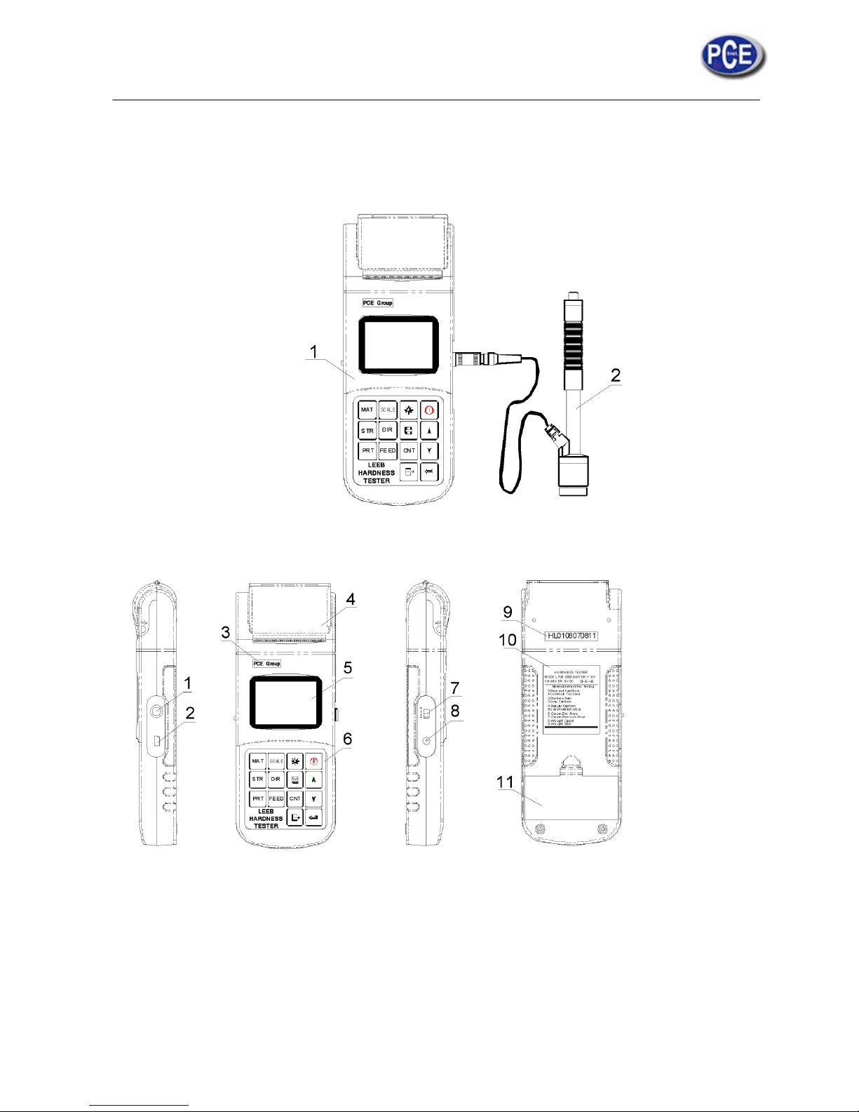
2.1.1 The Hardness Tester Appearance
1. Main unit
2. Impact device
2.1.2 Parts of the Main body
1 Socket of impact device 2 Socket of USB 3 LOGO 4 Paper compartment cover 5 LCD display 6
Keypad 7 Battery switch 8 Power jack 9 Serial Number 10 Product label 11 Battery compartment
cover
Page 8

2.1.3 D Type Impact Device
1 2 3 4 5 6 7
1 Release button 2 Loading tube 3 Guide tube 4 Coil unit
5 Connection cable 6 Impact body 7 Support ring
2.1.4 Different Types of Impact Device
DC DL C D+15 E G
2.2 Main Screen
Below is the main display screen:
Instruction of the Main Display Screen:
Hardness Scale
Average Icon
Direction
Battery Info
Impact Times
Measured Value
Material No
Memory Icon
Page 9
8
Material
:
The present presetting material.
Impact direction
:
The present impact direction.
Hardness scale
:
Hardness scale of the present measured value.
Battery information
:
Showing the rest capacity of the battery and the charging status.
Measured value
:
Display present single time measured value(without showing average icon), or
display the present mean value (with average icon prompting). “-HI-” means over conversion value or
measure range. “-LO-” means lower than conversion value or measure range.
Impact times: Times that have been impacted.
Average Icon
:
It will appear when showing the mean value of the measured values after reaching the
presetting impact times.
Memory Icon: It appears when operating the instrument memory.
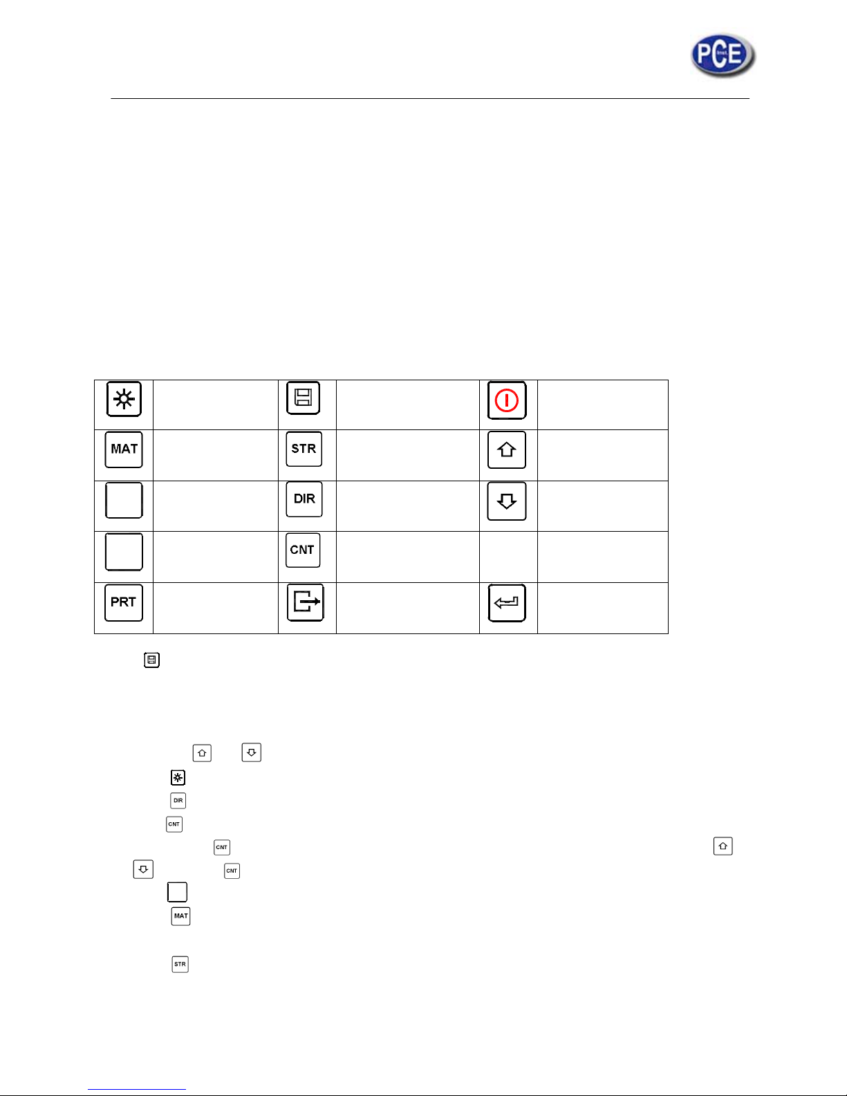
2.3 Keypad Definitions
Table 2-1
Turn on/off the
EL backlight
Data Save or Data
Delete
Turn the
instrument on/off
Material
Selection
Hardness/Strength
switch
Plus or Up
SCALE
Hardness Scale
Selection
Direction change
Minus or Down
FEED
Manual Paper
Feed
Impact Times set
Print data
Cancel or Exit
Data logging or
Enter
Press key to store present group of measured value into memory. This operation is only valid after
displaying the mean value.
z Press key and could display single measured value.
z Press key could switch on of off the background light of LCD.
z Press key to set the impact direction.
z Press key to change the impact times in one group. The impact times item will flash when first
pressing the key, and then the impact times value will plus or minus when pressing the or
key. Press key finally to exit from changing the impact times process.
z Press
SCALE
key to change the hardness scale.
z Press key to change the material. Presetting hardness scale recovers to HL automatically after
material presetting changed.
z Press key to switch between hardness test and strength test. Only D and DC type of impact
device has the function of strength testing. So hardness testing is the only selection if the impact
device is not D or DC type.
Page 10

z Press key to print out the measured values after measurement.
z Press
FEED
key to manually feed the paper.
2.4 Leeb Hardness Testing Principle
The basic principle is to use an impact body of certain weight impacts against the testing surface
under certain test force, then measure the impacting velocity and the rebounding velocity of the impact
body respectively when the spherically test tip is located 1mm above the testing surface.
The calculation formula is as follows:
HL=1000×VB/ VA
Where, HL—— Leeb hardness value
VB—— Rebounding velocity of the impact body
VA—— Impacting velocity of the impact body
3 Preparation
3.1 Instrument Preparation and Inspection
Verification of the instrument is by using standard test block. The error and repeatability of
displayed value should be within the regulation of Appendix table 2. The instrument and impact device
must be calibrated using a standard hardness block before use as the first time, or having not been used
for a long time, or having reset the instrument system.
Press key, meanwhile pressing down the key to power on the system. Then the user
calibration screen shows as left below.
Test for 5 points on the standard hardness block.
It would display the average measured value
after measuring 5 times. Press key to
change to its nominal value.
Press key to confirm the calibration finally. Or
press the key to cancel the calibration.
Range of adjustment: ±30HL.
The measurement parameters, including the material setting, the hardness scale and the impact
direction can’t be changed during calibration.
3.2 Impact
Device
Selection
Refer
to Appendix
Table 1 and Table 3 for selection of impact device.
Note:Use a calibrated hardness tester, test the standard test block
downward vertically for 5 times, the arithmetical average value compare with
the value of standard test block. If this value exceeds the standard value, could
use the function of user calibration to adjust.
Page 11

3.3 Prepar
a
Prepar
a
z In the
proces
s
z
Too bi
g
to be
m
z
Suppo
r
set on
t
wobbl
e
z Curve
d
surfac
e
smalle
r
should
z The sa
m
3.
z For th
e
Table
3
z Coupli
surfac
e
directi
o
b
endi
n
b
ig e
n
reinfo
r
z Magn
e
tion of the
tion for sa
m
preparatio
n
ing on the
roughnes
s
easured m
u
t of test sa
m
t
he smooth
i
.
surface:
T
to be test
e
than 50m
m
be chosen.
ple shoul
d
sample
w
.
ng. Light-
w
must be
f
n must b
e
g piece, it
c
ough, and
ced or sup
p
tism of the
Sample Su
r
ple surfa
c
processi
n
surface of
s
of the bei
n
st appear
m
m
ple. Sup
p
ng and sta
b
he best te
s
d is smalle
(G type
o
have eno
u
ith harden
e
eight sam
p
lat and sm
o
vertical t
o
an be def
o
accordingl
y
orted at its
sample its
e
face
e should c
o
g for sam
p
ample sho
u
n
g measur
e
etallic lus
t
ort is no n
e
le plane.
T
ting surfa
c
r than 30m
m
f impact
d
gh thickne
s
d layer o
n
le must b
e
oth, and t
h
the coupl
e
rmed and
b
y
, the test
back.
lf should b
e
nform to t
h
le surface
,
ld be avoi
d
d surface
c
er, smooth
i
cessary fo
r
he sample
e of samp
l
(D, DC,
evice), the
s, minimu
m
surface, t
h
firmly c
o
ere is no
r
d surface.
ecome un
s
value ma
y
avoided.
e relative
r
the hardn
ed.
ould cause
ng and pol
i
heavy sa
m
must set a
b
e is flat.
W
D+15,C, E
small supp
thicknes
s
e depth of
upled wit
h
edundant
c
When the
table, eve
n
not be
a
equiremen
t
ess effect
o
error. So,
t
sh, withou
t
ple. Medi
u
solutely e
q
hen the c
u
and DL ty
p
ort ring or
of sample
hardened
l
a heavy
b
oupling ag
e
sample is
though it
s
ccurate. S
o
in Append
f being h
e
he surface
o
oil stain.
-weight
p
uability an
d
rvature ra
d
e of impa
c
the shaped
should con
f
ayer shou
l
ase plate.
B
nt existin
g
a big plat
e
weight an
d
the sam
p
ix Table 3.
ated or c
o
o
f the sam
p
p
arts must
without a
n
ius R of
t
t device) a
n
support ri
n
orm to Ta
b
d conform
oth coup
l
. The imp
a
, long rod
thickness
le should
ld
le
be
n
y
he
n
d
gs
le
to
ed
ct
or
is
be
Page 12
4 Testin
g
4.1 Start-U
p
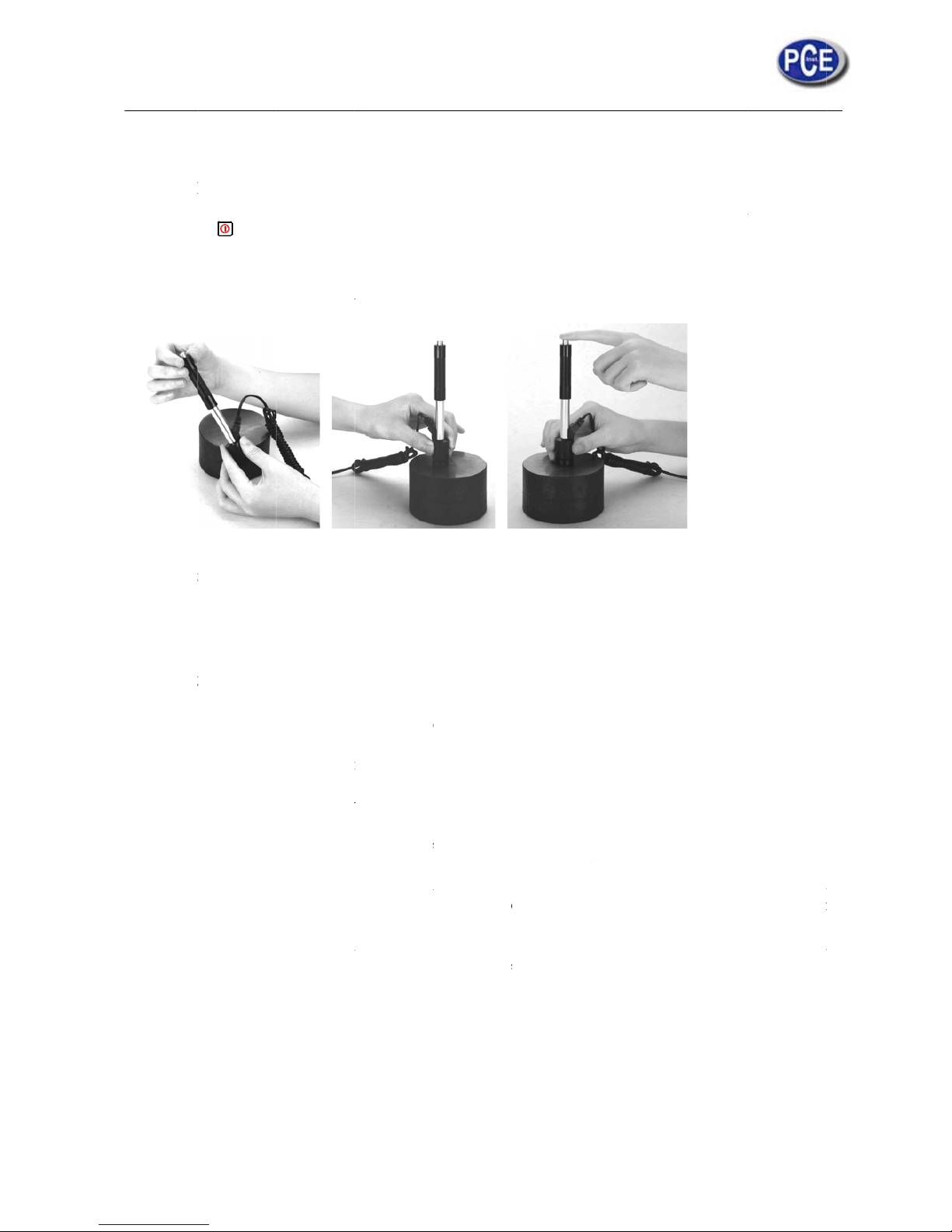
z Insert
t
z Press t
h
4.2 Loadin
g
Pushing
starting po
s
4.3 Locali
z
Press th
e
should be
v
4.4 Testin
g
z Press
t
device
the axi
z Each
m
disper
s
z The di
s
testing
z If wan
t
is nee
d
hardne
hardne
of mo
r
averag
e
indivi
d
correl
a
Progra
m
p
he plug of
t
e key,
the loading
ition or us
i
ation
impact de
v
ertical to t
h
he release
as well as
s of the im
p
easure ar
e
ion should
tance bet
w
sample sh
o
accurate c
ed to get
ss tester an
d
ss value, e
a
e than thre
e
value an
d
ual hardne
tive data.
he impact
d
now powe
r
-tube dow
n
ng other m
e
ice suppor
t
e testing s
u
button on
t
the operat
o
act device.
a of the sa
m
not more t
h
een any t
w
uld confor
m
onversion
f
conversio
n
correspo
n
ch measur
e
indentati
o
correspo
n
ss contrast
i
evice into
is on. The
wards unti
l
thod locki
n
t
ing ring fi
r
rface.
he upside
r are all re
q
m
ple usual
l
an mean v
a
o impact p
o
to the re
g
rom the L
e
relations
ding hard
n
homogen
e
ns which
n
ding hardn
e
ve curve.
C
the socket
o
instrument
contact is
f
g the imp
a
mly on the
of the imp
a
q
uired to b
e
y need 3 t
o
lue±15HL
.
ints or fro
m
ulation of
T
eb hardnes
s
for the sp
e
ess tester t
o
ously 5 p
o
eed conve
r
ss averag
e
ontrastiv
e
f impact d
e
is in work
i
elt. Then a
l
ct body.
surface of
t
ct device
t
stable no
w
5 times
o
the cent
e
able 4-1.
value to
o
cial mate
r
test at the
ints of Lee
b
sion hardn
e
value as
c
curve at l
vice on th
e
ng mode.
l
low it to sl
he sample,
o test. Th
e
. The acti
f testing o
p
r of any i
m
ther hardn
e
ial. Use i
n
same sam
p
hardness
ss, using
L
orrelative
v
east shoul
d
instrume
n
owly retur
n
the impact
sample a
n
on directio
n
eration. T
h
pact point
t
ss value, c
o
spection q
u
le respecti
v
value in th
e
eeb hardn
e
alue respe
include t
h
t.
to the
direction
d the imp
a
should p
a
e result d
a
o the edge
ntrastive t
e
alified Le
ely. For e
a
surroundi
n
ss arithme
t
c
tively, m
a
ct
ss
ta
of
st
eb
ch
ng t
ic
ke
of
Page 13
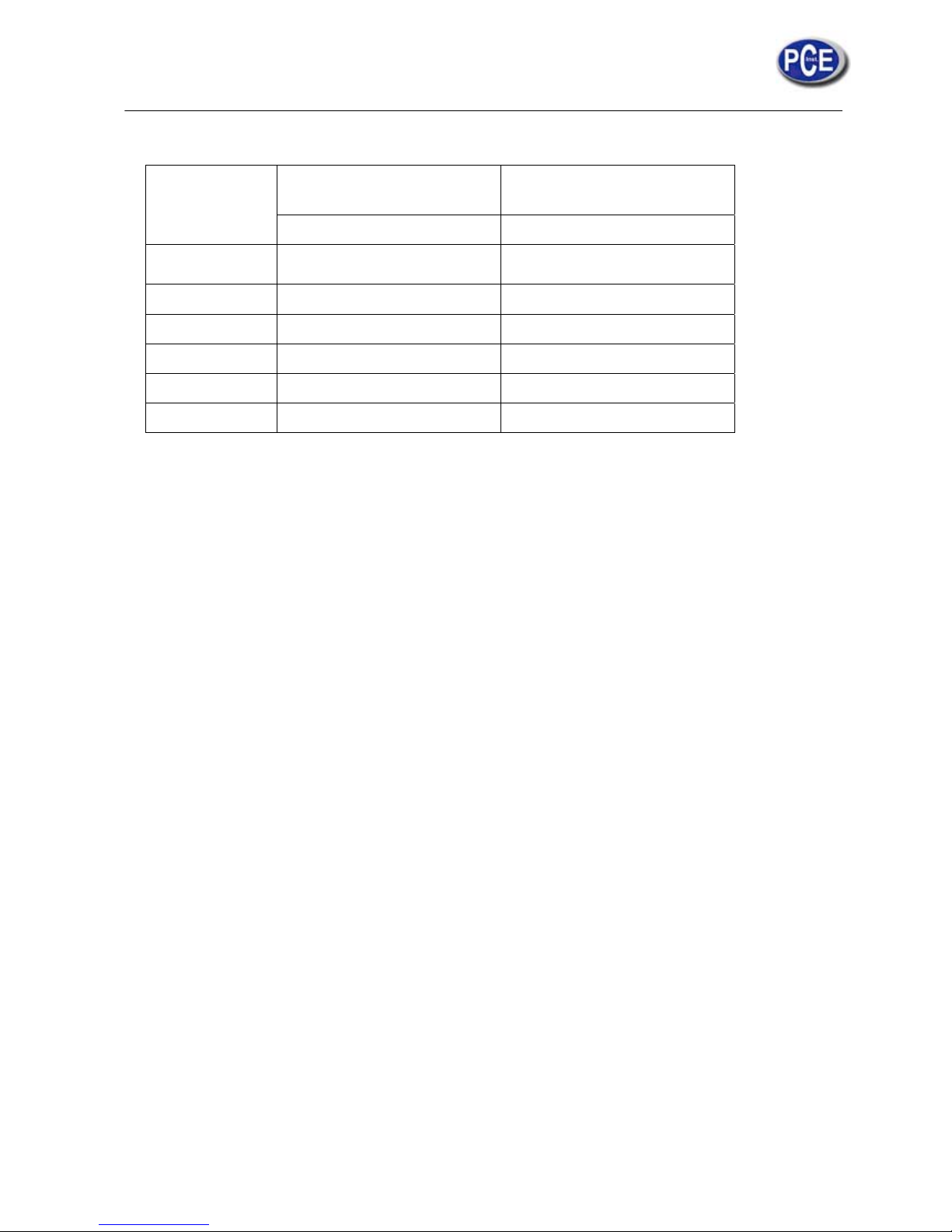
Table 4-1
Type of Impact
Device
Distance of center of the two
indentations
Distance of center of the
indentation to sample edge
Not less than (mm) Not less than (mm)
D、DC
3 5
DL 3 5
D+15 3 5
G 4 8
E 3 5
C 2 4
4.5 Read Measured Value
After each impact operation, the LCD will display the current measured value, impact times plus
one, the buzzer would alert a long howl if the measured value is not within the valid range. When
reaching the presetting impact times, the buzzer will alert a long howl. After 2 seconds, the buzzer will
alert a short howl, and display the mean measured value.
4.6 Notification
z Replacing the impact device must be done during Power off. Otherwise the main body could not
identify the type of the impact device, and it may damage the circuit board of the main body.
z You could not save the current test value if the impact time is less than the presetting times value.
z Only type D and type DC of impact device have the function of strength test option. You can not
change the setting to strength testing when using other types of impact device. The setting would
be set to hardness testing automatically after replacing the impact device whether the setting is
hardness testing or not before.
Not all materials could convert to all hardness scale value. The hardness scale is reset to HL
automatically after changing the material. So select material firstly before changing the hardness scale.
Page 14

5 Operation Detail
5.1 Power On/Off
Press to power on the instrument. Be sure to plug in the impact device before powering on. The
system would automatically detect the type of the impact device during power up, and would display
this information on the screen. Users should pay attention to the probe type displayed on the screen.
After pausing for several second, the screen will exit and enter the main display screen as following:
The instrument can be turned off by pressing the key while it is working. The tool has a special
memory that retains all of its settings even when the power is off.
Note: If the instrument is in power off condition, it will turns on automatically after the charge
power is connected.
5.2 Material Setting
Press key to change the material to the one you want to preset. Hardness scale recovers to HL
automatically after material presetting changed. Please select material firstly, then select hardness
scale.
In hardness testing, you can select the material among the following materials: Steel and Cast
Steel、Cold Work Tool Steel、Stainless Steel、Gray Cast Iron、Nodular Cast Iron、Cast Aluminum
Alloys、Copper-Zinc Alloys、Copper-Aluminum Alloys、Wrought Copper and Wrought Steel. The
relationship between the material number displayed on the instrument screen and the material is as
follows:
Table 5-1
Material No. Material Material No. Material
0 Steel and cast steel 5 Cast aluminum alloys
1 Cold work tool steel 6 Copper-Zinc alloys
2 Stainless steel 7 Copper –Aluminum alloys
3 Gray cast iron 8 Wrought copper
4 Nodular cast iron 9 Wrought steel
Page 15
In strength testing, the following materials are selectable: Mild Steel、High-Carbon Steel、Cr
Steel、Cr-V Steel、Cr-Ni Steel、Cr-Mo Steel、Cr-Ni-Mo Steel、Cr-Mn-Si Steel、Super Strength
Steel and Stainless Steel. The relationship between the material number displayed on the instrument
screen and the material is as follows:
Table 5-2
Material No Material Material No Material
0 Mild steel 5 Cr-Mo steel
1 High carbon steel 6 Cr-Ni-Mo steel
2 Cr steel 7 Cr-Mn-Si steel
3 Cr-V steel 8 Super strength steel
4 Cr-Ni steel 9 Stainless steel
5.3 Hardness/Strength testing
Press key to switch between hardness testing and strength testing (бb) .
Note: Only D and DC type of impact device has the function of strength testing. So hardness testing
is the only selection if the impact device is not D or DC type.
In hardness testing, Press
SCALE
key to change the hardness scale. The supported hardness scale
includes: HL, HV, HB, HRC, HS, HRB and HRA.
Note:
z Here only displays the valid hardness scale for the present selected impact device and material.
It would not display the hardness scale which is not valid.
z Please select material firstly, then select hardness scale.
z Presetting hardness scale recovers to HL automatically after presetting material is changed.
5.4 Impact Direction Setting
Press the key to move to the impact direction that you will preset.
5.5 Average Times Setting
You could modify average times within the range of 1 to 32 as following:
1) Press key in testing state. The impact times item will begin to flash.
2) Press or key to set the average times to the number you want.
Press key finally to exit from the operation.
Page 16

15
5.6 Data logging
At most one hundred files (F00-F99, one group as one file) can be stored inside the gauge. By
simply pressing the key after a new measurement finishes-the screen showing the “AVE” icon, the
measured hardness/strength group values will be saved to memory. The new saved file is appended as
the last file of the memory. This function provides the user with the ability to view/delete a file/group
previously saved in memory.
5.6.1 Viewing stored file/Group
To view the memory data, follow the steps:
1) Press the key to activate the data logging function. The memory icon will appear. It will display
the current file name, the test parameter of the group data and the mean value of the group. If there
is no data in the memory, it will display: <E04>, which means no memory data, and then return
back.
2) Use the key and the key to select the desired file to view.
3) Press the key to see details of that group data.
4) Use the key and the key to view each single measured data in that group while viewing
details.
5) Press the key to return to previous screen at any time during data logging.
5.6.2 Deleting selected file/Group
The user may require deleting a file from the instrument memory. The procedure is outlined in
the following steps.
1) Press the key to activate the data logging function. The memory icon will appear. It will display
the current file name, the test parameter of the group data and the mean value of the group. If there
is no data in the memory, it will display: <E04>, which means no memory data, and then return
back.
2) Use the key and the key to scroll to the file that will be deleted.
3) Press the key on the desired file. It will automatically delete the file, and display “-DEL”.
4) Press the key, at any time, to exit the data logging function and return to measurement mode.
Note
:
Do not shut down the instrument while deleting data. It could lead to unpredicted
consequence if shutting down while deleting.
5.7 Print Function
At the end of the inspection process, or end of the day, the user may require the readings be
printed. You can print out the measurement result immediately after each testing process, by easily
pressing the
key. If you want to print the data stored in the instrument memory, then following is
the steps:
1. Press the key to activate the data logging function. The memory icon will appear.
2. Use the key and the key to select the desired file.
3. Press the key to print the selected file. This operation will print out all the data in current file.
4. Press the key to exit the data logging functions and return to measurement mode.
Note:
z Printing function is unavailable while charging.
z Printing can be stopped by pressing the key.
z Do not open the cover of the paper compartment during printing. Otherwise the instrument may
not print normally.
z Over high ambient humidity (above 85% of relative humidity) or over low ambient humidity
(below 20% of relative humidity) may reduce the print quality.
z Printing with paper that has been stored for over long period of time or of poor quality may
Page 17

reduce the print quality or even damage the printer.
When the printer is powered on and ready for printing, press
FEED
key then the instrument will start
manual paper feeding. Press and keep holding the
FEED
key to start paper feeding, while releasing the
key to stop paper feeding.
Note: Manual paper feeding is unavailable while charging.
5.8 System Reset
Press down the
SCALE
key while powering on the instrument will restore factory defaults. The
only time this might possibly helpful is if the parameter in the instrument was somehow corrupted.
5.9 EL Backlight
With the EL background light, it is convenient to work in the dark condition. Press key to
switch on or switch off the background light at any moment as you need after power on. Since the EL
light will consume much power, turn on it only when necessary.
5.10 Auto Power Off
The instrument features an auto power off function designed to conserve battery life. If the tool is
idle (neither measuring nor any key operation) for 5 minutes, it will turn itself off. Before powering
off, the LCD display of the instrument will continue flashing for 20 seconds. Except key , press any
key could stop the twinkle of LCD screen and stop the operation of power off at the moment.
While the voltage of the battery is too low, the display will show <E00>, then power off
automatically.
When the instrument is being charged, the Auto Power Off will not function.
5.11 Paper Installation
z Hold Both ends of the paper
compartment with fingers and open
the compartment cover with
moderate strength.
z According to the illustration, put the
paper into the paper compartment
with attention to the paper direction.
If the paper is misplaced, the
instrument will fail to print.
z Pull a trip of paper out of the
compartment.
z Make sure that the paper is well in
place and close the paper
compartment cover.
5.12 Battery Charge
The instrument uses a NI-MH battery pack as its power source. When the battery pack almost
runs out, the battery symbol on the display will glint . It needs charging as soon as possible. Try
to drain your battery pack as fully as possible before it is charged for longest battery service.
Page 18

z The battery switch should be at ‘ON’ condition before charging.
z Plug the power adapter into the mains supply power socket and then plug the charger connector
into the power jack of the instrument. If the instrument is in power off condition, it will turns on
automatically after the charger plug is inserted into the power jack. The battery symbol will
alternately shows between and when charging. The more of the dark part indicates
the more close to full capacity.
z When the battery is fully charged, the battery symbol on the display will glint .
z Please use the configured AC-DC adapter to charge the battery pack.
Warning: When the battery pack is being charged, printing or paper feeding is unavailable.
5.13 Battery Replacement
When the battery pack fails to be charged, the user should replace the batteries following the program
below:
z Power down the instrument.
z Take off the battery compartment cover and take out the battery pack.
z Insert the connection plug of the new battery pack into the socket on the circuit board.
z Reset the battery cover.
z Turn on the instrument to check.
Warning: Please pay much attention to the polarity of the battery during battery replacement.
5.14 Connecting to a Computer
Insert one connection plug of the transmission cable into the USB socket on the right side of main
body, and insert the another plug into the USB port on the back of computer box. Refer to the manual
of the DataPro software for detailed information.
5.15 Error Code Reference
Error Code Explanation Error Code Explanation
E00 Battery exhausted E05 Can not print
E01 Value out of range E06 Battery Charging
E02 Measurement not finished E07 No paper for printing
E03 Data already saved E08 Over Temperature
E04 No memory data E09
6 Maintenance & Servicing
6.1 Impact Device Maintenance
z After the impact device has been used for 1000--2000 times, please use the nylon brush provided
to clean the guide tube and impact body. When cleaning the guide tube, unscrew the support ring
first, then take out the impact body, spiral the nylon brush in counter-clock direction into the
bottom of guide tube and take it out for 5 times, and then install the impact body and support ring
again.
z Release the impact body after use.
z Any lubricant is absolutely prohibited inside the impact device.
Page 19

6.2 Instrument Maintenance Program
z When using standard Rockwell hardness block to testing, if all the error is bigger than 2 HRC, it
may be the invalidation of impacted ball top caused by abrasion. Changing the spherical test tip or
impact object should be considered.
z When the hardness tester appears some other abnormal phenomena, please do not dismantle or
adjust any fixedly assembled parts. Fill in and present the warranty card to us. The warranty
service can be carried on.
6.3 Fault Analysis & Evacuation
Fault Appearance Fault Analysis Handling method
Charge failure
Battery failure Replace the battery with
a new pack
The battery is switched off Switch on the battery
No measured value Impact device cable failure Replace the cable
Failure power on
Battery exhaustion Charge the battery
The battery is switched off Switch on the battery
6.4 Notice of Transport and Storage Conditions
z Keep it away from vibration, strong magnetic field, corrosive medium, dumpiness and dust.
Storage in ordinary temperature.
z With original packing, transport is allowed on the third grade highway.
Page 20

APPENDIX
Table 1
Material Method
Impact device
D/DC D+15 C G E DL
Steel and cast
steel
HRC 2068.5
19.367
.9
20.069
.5
22.470.7
20.668
.2
HRB
38.499
.6
47.799.
9
37.099
.9
HRA
59.185
.8
61.788.0
HB
12765
1
80638 80683 90646 83663 81646
HV 83976 80937 80996 841042 80950
HS
32.299
.5
33.399
.3
31.810
2.1
35.8102.6 30.696
.8
Cold work
tool steel
HRC
20.467
.1
19.868
.2
20.768
.2
22.670.2
HV 80898 80935
10094
1
821009
Stainless steel
HRB
46.510
1.7
HB 85655
HV 85802
Grey cast iron
HRC
HB 93334 92326
HV
Nodular cast
iron
HRC
HB
13138
7
127364
HV
Cast aluminum
alloys
HB 19164 23210 32168
HRB
23.884
.6
22.785
.0
23.885.
5
BRASS(copper-
zinc alloys)
HB 40173
HRB
13.595
.3
BRONZE(copp
er-aluminum/tin
alloys)
HB 60290
Wrought copper
alloys
HB 45315
Page 21

Table 2
No. Material HLD Strength σb(MPa)
1 Mild steel 350522 374780
2 High-Carbon steel 500710 7371670
3 Cr steel 500730 7071829
4 Cr-V steel 500750 7041980
5 Cr-Ni steel 500750 7632007
6 Cr-Mo steel 500738 7211875
7 Cr-Ni-Mo steel 540738 8441933
8 Cr-Mn-Si steel 500750 7551993
9 Super strength steel 630800 11802652
10 Stainless steel 500710 7031676
Page 22

Table 3
Type of impact device DC(D)/D
L
D+15 C G E
Impacting energy
Mass of impact body
11mJ
5.5g/7.2g
11mJ
7.8g
2.7mJ
3.0g
90mJ
20.0g
11mJ
5.5g
Test tip hardness:
Dia. Test tip:
Material of test tip:
1600HV
3mm
Tungsten
carbide
1600HV
3mm
Tungsten
carbide
1600HV
3mm
Tungsten
carbide
1600HV
5mm
Tungsten
carbide
5000HV
3mm
synthetic
diamond
Impact device diameter:
Impact device length:
Impact device weight:
20mm
86(147)/
75mm
50g
20mm
162mm
80g
20mm
141mm
75g
30mm
254mm
250g
20mm
155mm
80g
Max. hardness of sample 940HV 940HV 1000HV 650HB 1200HV
Mean roughness value
of sample surface Ra:
1.6μm 1.6μm 0.4μm 6.3μm 1.6μm
Min. weight of sample:
Measure directly
Need support firmly
Need coupling tightly
>5kg
25kg
0.052kg
>5kg
25kg
0.052kg
>1.5kg
0.51.5kg
0.020.5kg
>15kg
515kg
0.55kg
>5kg
25kg
0.052kg
Min. thickness of
sample Coupling tightly
Min. layer thickness for
surface hardening
5mm
≥0.8mm
5mm
≥0.8mm
1mm
≥0.2mm
10mm
≥1.2mm
5mm
≥0.8mm
Size of tip indentation
Hardness
300HV
Indentation
diameter
Depth of
indentation
0.54mm
24μm
0.54mm
24μm
0.38mm
12μm
1.03mm
53μm
0.54mm
24μm
Hardness
600HV
Indentation
diameter
Depth of
indentation
0.54mm
17μm
0.54mm
17μm
0.32mm
8μm
0.90mm
41μm
0.54mm
17μm
Hardness
800HV
Indentation
diameter
Depth of
indentation
0.35mm
10μm
0.35mm
10μm
0.35mm
7μm
--
--
0.35mm
10μm
Available type of impact
device
DC: Test
hole or
hollow
cylindrical;
DL:Testslen
der narrow
groove or
hole
D+15:
Test
groove
or
reentra
nt
surfac
e
C
: Test
small,light,
thin parts
and
surface of
hardened
layer
G
: Test
large,
thick,heav
y and
rough
surface
steel
E: Test
super high
hardness
material
Page 23

Table 4
N11
1
o. T
y
1 Z1
2 Z1
4
3 Z2
4 HZ
1
5 HZ1
6 HZ1
7
K1
8 K1
4
9 HK
0 HK1
1 HK1
2
U
y
pe
0-15
.5-30
5-50
1-13
2.5-17
6.5-30
0-15
.5-30
11-13
2.5-17
6.5-30
N
Sketch
conve
n
Suppor
t
of non-
tional
ing ring
For t
e
For t
e
s
For t
e
For
t
For
t
s
For
t
s
For
t
s
For
t
s
u
For
s
For
s
u
For
s
u
For t
e
surfac
e
Rema
r
sting cylin
surface R1
sting cylin
urface R1
4
sting cylin
surface R
2
esting cyli
n
surface R1
esting cyli
n
urface R1
2
esting cyli
n
urface R1
6
esting sph
e
urface SR1
esting sph
e
rface SR1
4
testing sph
e
urface SR1
testing sph
e
rface SR1
2
testing sph
e
rface SR1
6
sting cylin
,radius adj
u
r
ks
drical outsi
0R15
drical outsi
.5R30
drical outsi
5R50
drical insi
d
1R13
drical insi
d
.5R17
drical insi
d
.5R30
rical outsi
d
0SR15
rical outsi
d
.5SR30
rical insid
e
1SR13
rical insid
e
.5SR17
rical insid
e
.5SR30
drical outsi
stable R1
0
2
de d
e
d
e
e
e
e
e
e
d
e
∞
2
 Loading...