

Page 1
© PCE Instruments
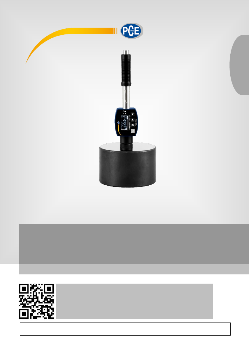
PCE-2550 Hardness Tester
User Manual
User manuals in various languages (français,
italiano, español, português, nederlands, türk, polski,
русский, 中文) can be found by using our
product search on: www.pce-instruments.com
Last change: 28 December 2021
v1.0
English
Page 2

Contents
1 Safety notes ........................................................................................... 1
2 Measuring principle .............................................................................. 2
3 Specifications ........................................................................................ 2
3.1 Technical specifications ................................................................................................... 2
3.2 Delivery scope.................................................................................................................. 5
3.3 Optional accessories ........................................................................................................ 5
4 Device description ................................................................................ 6
5 Operation ............................................................................................... 8
5.1 Getting started.................................................................................................................. 8
5.2 Switching on the meter ..................................................................................................... 9
5.3 Check before measurement ............................................................................................. 9
5.4 Calibration .......................................................................................................................10
5.5 Measurement ..................................................................................................................10
5.6 Save and delete ..............................................................................................................11
5.7 Menu structure ................................................................................................ ................12
6 Maintenance and cleaning ................................................................. 14
6.1 Batteries (no rechargeable batteries)...............................................................................14
6.2 Troubleshooting ..............................................................................................................14
6.3 Maintenance of the impact body ......................................................................................14
7 Contact ............................................................................................... 15
8 Disposal ............................................................................................... 15
© PCE Instruments
Page 3

© PCE Instruments
1
1 Safety notes
Please read this manual carefully and completely before you use the device for the first time. The
device may only be used by qualified personnel and repaired by PCE Instruments personnel.
Damage or injuries caused by non-observance of the manual are excluded from our liability and
not covered by our warranty.
• The device must only be used as described in this instruction manual. If used otherwise,
this can cause dangerous situations for the user and damage to the meter.
• The instrument may only be used if the environmental conditions (temperature, relative
humidity, …) are within the ranges stated in the technical specifications. Do not expose
the device to extreme temperatures, direct sunlight, extreme humidity or moisture.
• Do not expose the device to shocks or strong vibrations.
• The case should only be opened by qualified PCE Instruments personnel.
• Never use the instrument when your hands are wet.
• You must not make any technical changes to the device.
• The appliance should only be cleaned with a damp cloth. Use only pH-neutral cleaner,
no abrasives or solvents.
• The device must only be used with accessories from PCE Instruments or equivalent.
• Before each use, inspect the case for visible damage. If any damage is visible, do not
use the device.
• Do not use the instrument in explosive atmospheres.
• The measurement range as stated in the specifications must not be exceeded under
any circumstances.
• Non-observance of the safety notes can cause damage to the device and injuries to
the user.
We do not assume liability for printing errors or any other mistakes in this manual.
We expressly point to our general guarantee terms which can be found in our general terms of
business.
If you have any questions please contact PCE Instruments. The contact details can be found at
the end of this manual.
Page 4
© PCE Instruments
2
2 Measuring principle
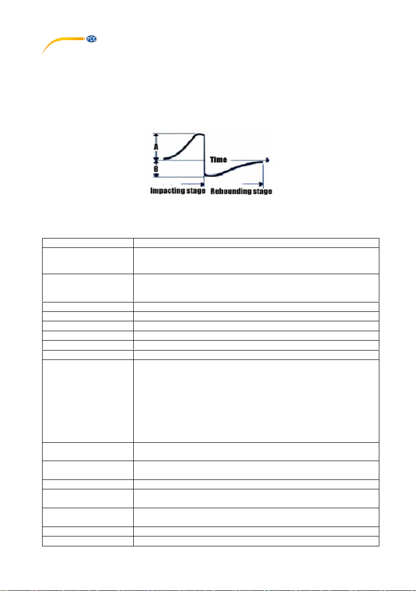
An impact body of known weight is propelled against the measuring surface. The hardness value
is calculated from the rebound velocity and the impact velocity at 1 mm distance from the
measuring surface using the following formula:
HL = 1000×VB/VA
HL-- Hardness according to Leeb
VB-- Rebound velocity
VA-- Impact velocity
3 Specifications
3.1 Technical specifications
Measurement ranges
170 ... 960 HLD
Accuracy
on 760±30HLD test block = ±6 HLD
on 530±40HLD test block = ±10 HLD
Repeatability
on 760±30HLD test block = 6 HLD
on 530±40HLD test block = 10 HLD
Measuring direction
360°
Impact device
D-type
Measuring units
HL, HB, HRB, HRC, HRA, HV, HS
Selectable materials
10
Calibration
Possible on included hardness test block
Display
OLED display 128 x 64 pixels
Internal memory
1 ...373 measurement series (with averaging from 31
measurements)
1 ... 2688 measurement series (with averaging from 1
measurement)
approx. 2000 measurement series with AVG after 3 measurements
Measurement series consists of mean value / direction of
measurement / material / number of measurements for averaging /
measured values of each individual measurement
Automatic power-off
function
yes
Power supply
2 x CR2016 button cells
(not rechargeable)
Operating time
approx. 8 h continuous operation
Interface
Micro USB
Note: For software use only
Environmental
conditions
0 ... +40 °C / 32 ...104 °F, ≤90 % RH
Dimensions
145.5 x 32 x 26 mm / 5.73 x 1.26 x 1.02“
Weight
160 g / <1 lb
Page 5
© PCE Instruments
3
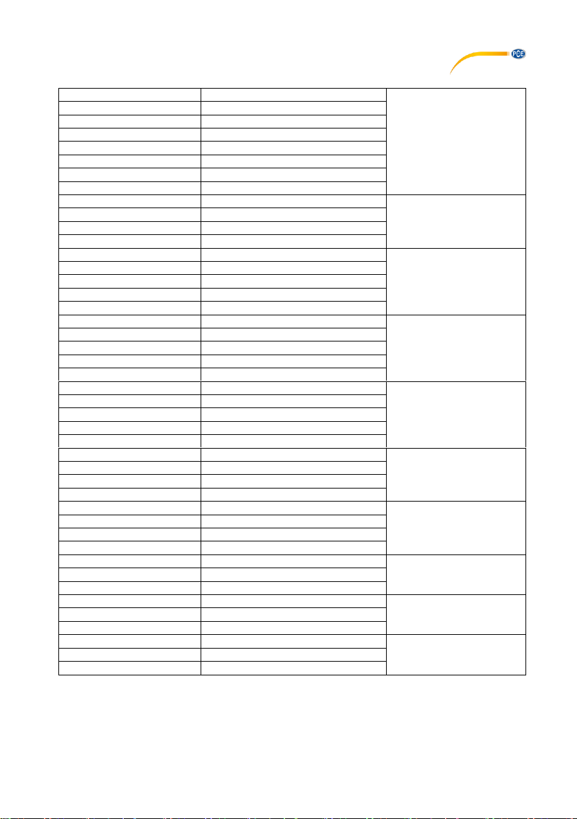
Measurement ranges according to material and hardness scale
Material
Steel and cast steel
Cast Steel
HL / HV / HB / HRC / HS
/ HRB / HRA
Scale
Rockwell, Brinell, Vickers, Shore
Measurement range
HRC: 17.9 ... 68,5
HRB: 59.6 ... 99,6
HRA: 59.1 ... 85,8
HB: 127 ... 651
HV: 83 ... 976
HS: 32.2 ... 99,5
Material
Cold rolled steel
CWT Steel
HL / HV / HRC
Scale
Rockwell, Vickers
Measurement range
HRC: 20.4 ... 67,1
HV: 80 ... 898
Material
Stainless steel
STAIN. Steel /
Stainless Steel
HL / HV / HB / HRB
Scale
Rockwell, Brinell, Vickers
Measurement range
HRB: 46.5 ... 101,7
HB: 85 ... 655
HV: 85 ... 802
Material
Grey cast iron
GC Iron
Gray Cast Iron
HL / HB
Scale
Rockwell, Brinell, Vickers
Measurement range
HRC: ---
HB: 93 ... 334
HV: ---
Material
Ductile iron
NC Iron
HL / HB
Scale
Rockwell, Brinell, Vickers
Measurement range
HRC: ---
HB: 131 ... 387
HV: ---
Material
Cast aluminium alloy
Cast Alumin
HL / HB / HRB
Scale
Rockwell, Brinell
Measurement range
HRB: 23.8 ... 84,6
HB: 19 ... 164
Material
Brass
Cooper-Zinc
HL / HB / HRB
Scale
Rockwell, Brinell
Measurement range
HRB: 13.5 ... 95,3
HB: 40 ... 173
Material
Bronze
Cooper-Alumin
HL / HB
Scale
Brinell
Measurement range
HB: 60 ... 290
Material
Wrought copper alloy
Wrought Cooper
HL / HB
Scale
Brinell
Measurement range
HB: 45 ... 315
Material
Wrought steel alloy
Wrought Steel
HL / HB
Scale
Brinell
Measurement range
HB: 143 ... 650
Chart 2
Page 6
© PCE Instruments
4
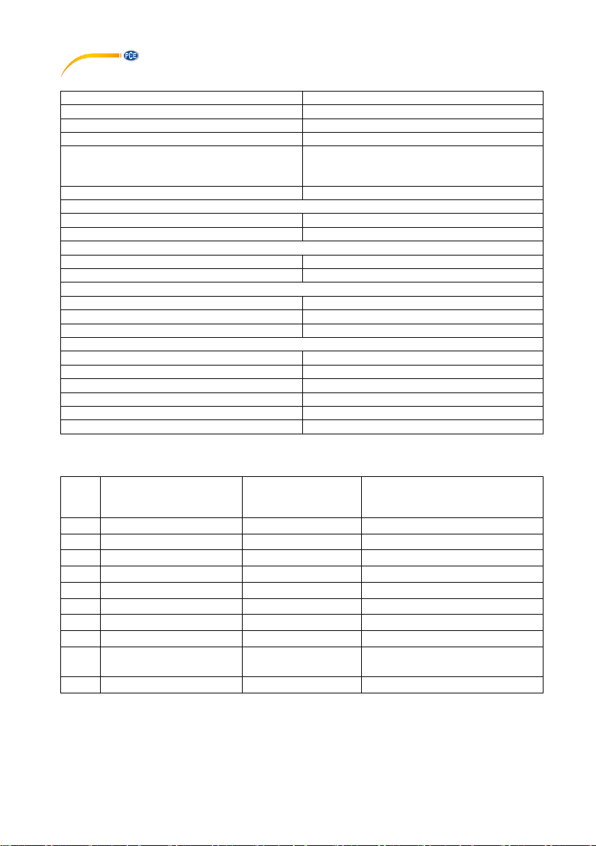
Specifications D-type impact device
Impact energy
11 Nmm / mJ
Impact body mass
5.5 g
Impact body
Tungsten carbide 3 mm
Application
Suitable for most applications
Test blocks
<500 HLD
~600 HLD
~775 HLD
Measurement range steel
81...654 HB
Max. roughness of the measuring surface
Peak-to-valley height Rt
10.0 µm
Mean roughness Ra / AA
2.0 µm = N7
Minimum sample mass
Compact design
5 kg
Coupled
2 kg
Minimum thickness of the sample
Compact design
25 mm
Coupled
3 mm
Surface layer thickness
≥0.8 mm
Test indentation diameter / depth
300 HV / 30 HRC
0.54 mm / 24 µm
600 HV / 55 HRC
0.45 mm / 17 µm
800 HV / 63 HRC
0.35 mm / 10 µm
Min. Radius of curvature
30 mm
Min. distance of impact points
3 mm
Min. distance to edge
5 mm
Chart 3
Conversion table HLD - Mpa
No.
Material
Hardness (HLD)
Tensile strength σ b (MPa)
1
Mild Steel
350 ... 522
374 ... 780
2
High-Carbon Steel
500 ... 710
737 ... 1670
3
Cr Steel
500 ... 730
707 ... 1829
4
Cr-V Steel
500 ... 750
704 ... 1980
5
Cr-Ni Steel
500 ... 750
763 ... 2007
6
Cr-Mo Steel
500 ... 738
721 ... 1875
7
Cr-Ni-Mo Steel
540 ... 738
844 ... 1933
8
Cr-Mn-Si Steel
500 ... 750
755 ... 1993
9
Super Strength Steel
630 ... 800
1180 ... 2652
10
Stainless Steel
500 ... 710
703 ... 1676
Chart 4
Note: The chart is for orientation purposes only!
Page 7

© PCE Instruments
5
3.2 Delivery scope
1 x hardness tester PCE-2550
1 x USB connection cable
1 x hardness test block
1 x cleaning brush
1 x support ring Ø14 mm
1 x carrying case
1 x user manual
3.3 Optional accessories
PCE-HAK, adaptor set, consisting of:
HZ12.5-17 Concave adaptor, 12.5...17 mm (inside)
HZ11-13 Concave adaptor, 11...13 mm (inside)
HZ16.5-30 Concave adaptor, 16.5...30 mm (inside)
Z10-15 Convex adaptor, 10...15 mm (outside)
Z14.5-30 Convex adaptor, 14.5...30 mm (outside)
Z25-50 Convex adaptor, 25...50 mm (outside)
HK11-13 Ball adaptor, 11...13 mm (inside)
HK12.5-17Sphere Ball adaptor, 12.5...17 mm (inside)
HK16.5-30Sphere Ball adaptor, 16.5...30 mm (inside)
K14.5-30 Ball adaptor, 14.5...30 mm (external)
K10-15 Ball adaptor, 10...15 mm (external)
UN Universal holder
Page 8
© PCE Instruments
6
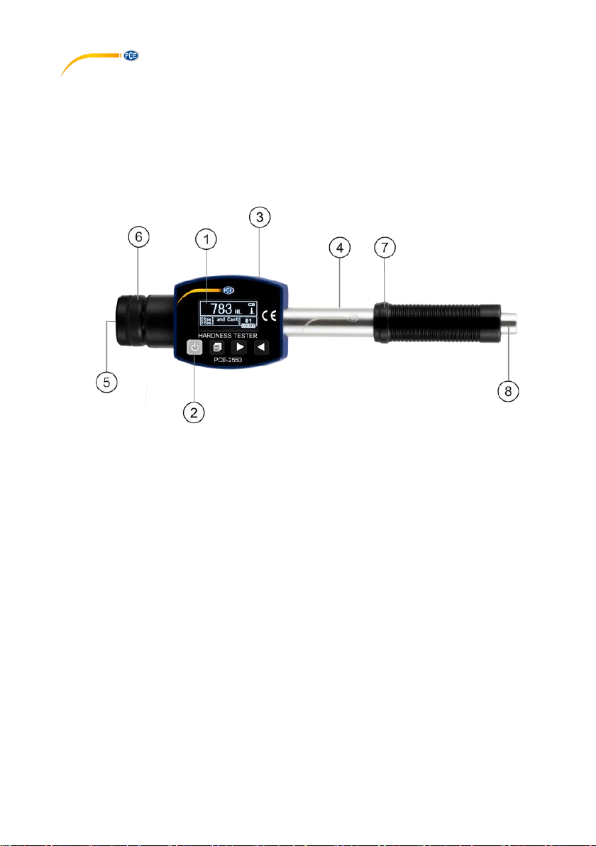
4 Device description
1. OLED display
2. Function keys
3. Micro USB interface
4. Impact device
5. Impact body
6. Support ring
7. Clamping slide
8. Trigger button
Page 9
© PCE Instruments
7
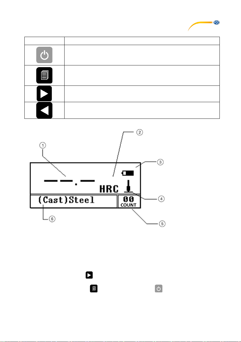
Function keys
Key
Function
-On/off
-In the menu: back
-In measurement mode: save AVG measurement
-Open menu
-In the menu: Select, confirm, scroll through options
-Cursor right/forward/down
-Decrease numbers
-Cursor left/back/up
-increase numbers
-In measurement mode: delete measurement
Display (in measuring mode)
1. Measured value / average value (AVG)
2. Hardness scale
3. Battery level indicator (no battery / charging via USB not possible)
4. Direction of impact / direction of measurement
5. Number of measurements carried out for averaging
6. Material
Hint: In measuring mode, the key can be used to switch directly between the hardness
scale / measuring direction / material and number of measurements to be used for averaging.
The changes are made with the key and confirmed with the key.
Page 10
© PCE Instruments
8
5 Operation
5.1 Getting started
General requirements for the material sample
- The surface temperature of the sample must be below 120 °C.
- The sample must meet the minimum thickness specified in the specifications.
- The surface to be tested should not be too uneven or rough. This could cause errors.
The sample being measured should be metallic, smooth and free of grease.
- The surface should not be magnetic.
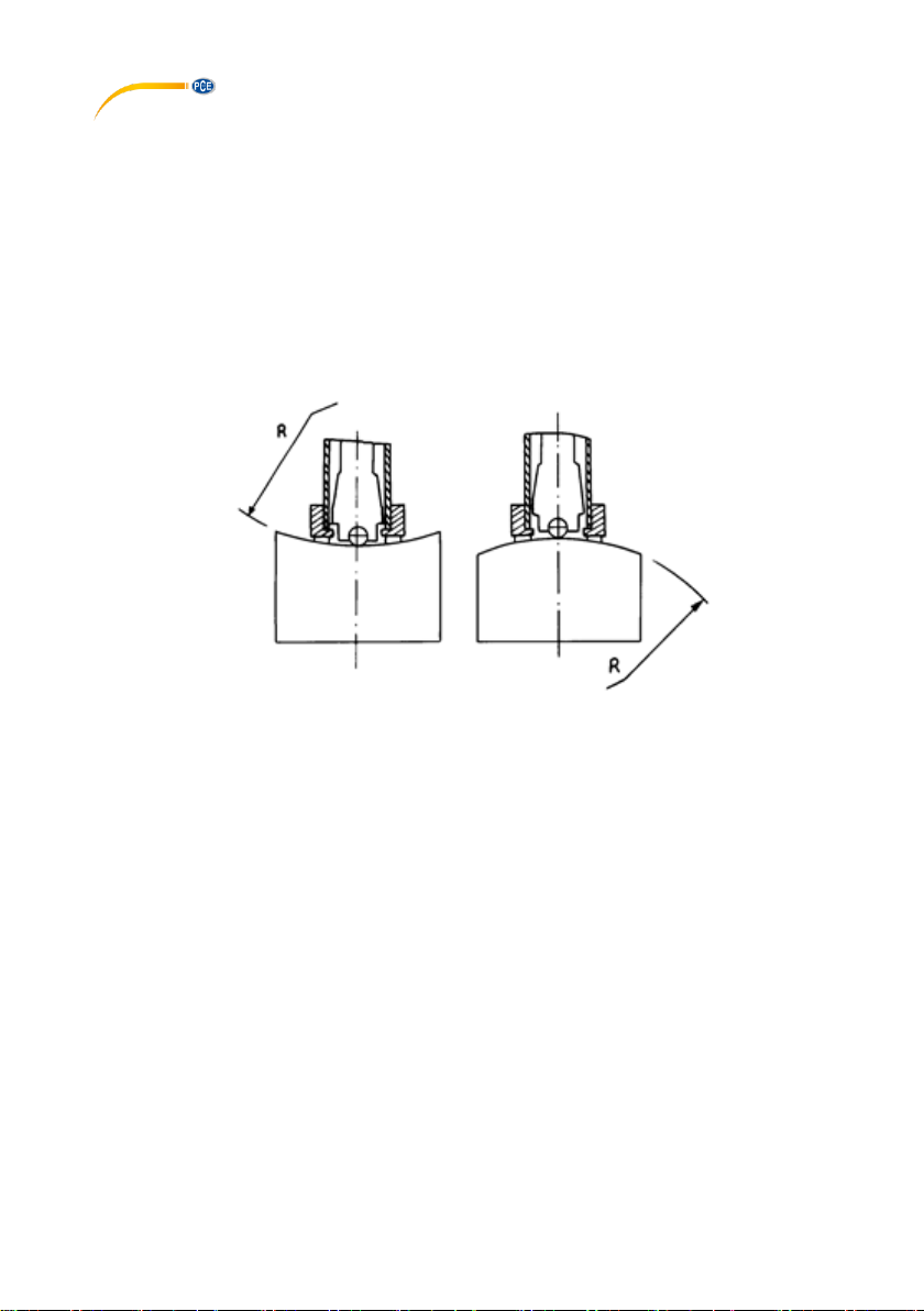
- If the radius of curvature R of the test surface is smaller than 30 mm, a small support
ring should be used.
- The intrinsic magnetism of the sample should be below 30 Gauss.
Page 11

© PCE Instruments
9
Requirements for the weight of the material sample
For samples which are heavier than five kilogrammes and have a compact design, no support is
necessary. Material samples with a weight of two to five kilogrammes but also heavier thin-walled
samples should be stabilised by means of a fixing device. This is to prevent the sample from being
deformed or displaced when touched. Material samples weighing less than two kilogrammes
should be firmly connected with a fixing device of more than five kilogrammes.
Coupling of the material sample to a fixing device/base plate
The contact surface between the material sample and the base plate should be even and smooth.
A thin, even layer of coupling gel should be applied between the base plate and the material
sample. The sample should then be pressed onto the base plate with circular movements to
achieve the best possible contact and distribution of the coupling gel. The direction of impact of
the measurement should be perpendicular to the contact surface. The material sample must not
have less than a minimum thickness of five millimetres for this method.
Requirements for material samples with hardened surface
Surface and case-hardened steel often gives deviating hardness readings due to its nonhomogeneous nature if the material thickness of the hardened layer is less than 0.8 mm.
Note
Good coupling needs experience. Insufficiently coupled samples cause large fluctuations in
measured values. Usually, the values are then lower than expected and an unusual noise
development occurs (acoustically clearly distinguishable from the measurement on the test
block). During the impact, the sample is subjected to a quite large (max. 900 N) but very shortlasting force. Therefore, clamping the material sample in a vice, for example, is unsuitable as a
support. The sample can shift minimally. Such faulty measurements can usually be recognised
by the large scatter of the measurement results.
5.2 Switching on the meter
To switch on the meter, press the key.
To switch off the meter, press and hold the key until "Power OFF" is displayed.
5.3 Check before measurement
Before measuring, check the meter with a hardness test block of known hardness, e. g. the
hardness test block that is included. For this purpose, make 5 measurements with vertical impact
direction. Keep a minimum distance of 3 mm to the next impact point and 5 mm to the edge. The
arithmetic mean of the 5 measurement results is the hardness value. In case of a larger deviation,
a calibration can be carried out.
Page 12
© PCE Instruments
10
5.4 Calibration
Before using the meter for the first time or if it has not been used for a long time, a calibration
should be carried out using the Leeb hardness test block that comes with the meter.
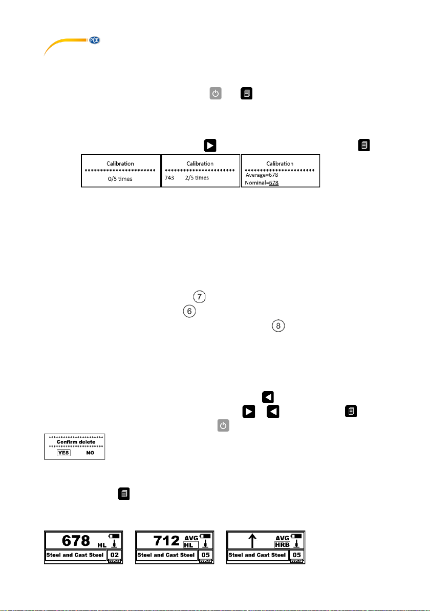
- When switching on, press and hold ´and until calibration mode opens.
- Now make 5 measurements on the hardness test block with vertical impact direction.
- After the 5 measurements, an ACTUAL [Average] and TARGET [Nominal] value
appears.
- In case of deviations, the [Nominal] value, which is written on the hardness test block,
can be entered with the key and confirmed with the key.
Hint:
The "Nominal" value can only be changed by ±15 HL. If the deviation is greater, we recommend
sending the device to PCE Instruments for calibration.
5.5 Measurement
5.5.1 Hardness measurement
Hint:
Before each measurement, make sure that the measurement settings shown in the display
correspond to the application.
- Press down the clamping slide to clamp the impact body.
- Then press the support ring vertically (90 °) onto the sample surface.
- Then release the impact body with the trigger button .
- We recommend making 5 measurements per test spot.
Hint:
The minimum centre to centre distance between two impact points should not be less than 3 mm
and the distance from an impact point to the edge of the sample must not be less than 5 mm.
If a measurement is faulty, it can be deleted by pressing the key.
The selection is made by pressing one of the two keys or . Confirm with the key. A
measurement can be cancelled by pressing the key.
When the set number of measurements has been made, the mean value AVG appears.
In AVG mode, the key can be used to subsequently change the hardness scale. The
conversion of the measured values then takes place automatically. An arrow in place of the
measured value means that the measured value / hardness scale does not match the conversion
range.
Page 13
© PCE Instruments
11
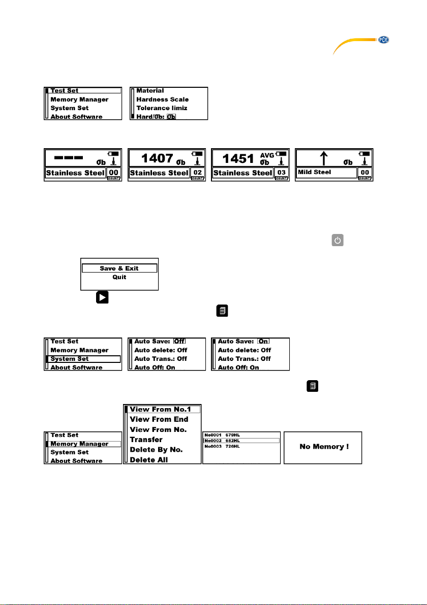
5.5.2 Tensile strength measurement (Mpa σb)
To measure the tensile strength, select the mode for tensile strength in the "Test Set" menu
under "Hard/σb": σb.
Then set the desired material as well as the impact direction and proceed with the measurement
as with the hardness measurement.
An arrow in place of the measured value means that the measured value is outside the
measurement range.
5.6 Save and delete
- To manually save the measurement series, press and release the key in AVG
mode. The following query then appears in the display:
- The key can now be used to scroll through the options.
- Confirmation is made by pressing the key.
Note: Automatic data storage can also be set in the "System Set" menu.
To access the saved values, go to the "Memory Manager" menu with the key. Here you can
retrieve the values. If "No Memory" is set, the memory is cleared.
Page 14
© PCE Instruments
12
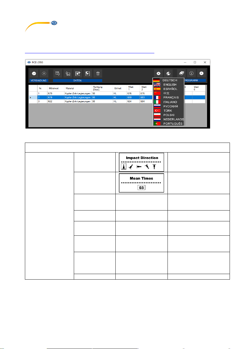
The saved measurement data can be transferred to the PCE-2550 software via the USB
interface. The software is available in several languages and can be downloaded free of charge
from the PCE Instruments website:
https://www.pce-instruments.com/english/download-win_4.htm
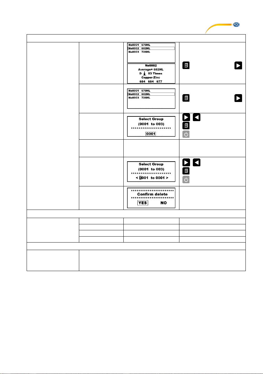
5.7 Menu structure
Test Set
Impact Direc.
Measuring direction /
direction of impact
Average
Number of measurements
from which the mean
value is to be formed.
1 ...31
Material
see chart 2 and 4
Depending on whether
hardness or tensile
strength is tested
Hardness Scale
HL, HV, HB, HRC,
HS, HRB, HRA
Depending on the selected
material
Tolerance Limit
Min / Max
0000 ... 9999
**not activated**
Hard / σb:
Hard or σb
Hard=hardness
measurement
σb=tensile strength
Sample Type:
D
Selection of impact body
D / DC / D+15 / C / G / DL
/ E
We only offer D
Standard:
EN
AS / EN
Page 15
© PCE Instruments
13
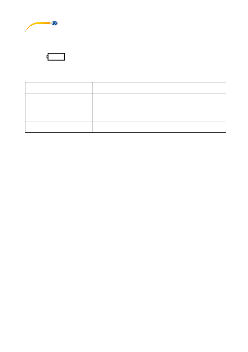
Memory Manager
View From No.1
Display from the
first
measurement
Selection is made with the
key. Scroll with the
key.
View From End
Display from the
last
measurement
Selection is made with the
key. Scroll with the
key.
View From No.
Display range
selection
Change number
Change position
Confirm
Transfer
Measurement data
transfer to the PCE-2550
software
Delete By No.
Deletion of
certain
measurements
Change number
Change position
Confirm
Delete All
Delete all
measurements
System Set
Auto Save:
Off / On
Automatic data storage
Auto Delete:
Off / On
Automatic deletion
Car Trans..:
Off / On
No function
Auto Off:
Off / On
Automatic power off
About Software
SoftWare Version Ver1.02
Code: PCE-190812SN
A11011909019
Page 16
© PCE Instruments
14
6 Maintenance and cleaning
6.1 Batteries (no rechargeable batteries)
When the icon flashes, the batteries must be replaced. To do this, unscrew the cover at
the back and remove the old batteries. Replace them with 2 new CR2016 button cells.
6.2 Troubleshooting
Problem
Cause
Solution
Meter does not switch on
Batteries flat
Replace the batteries.
No measured value is
displayed
No measurement
Check the release and
course of the impact body. If
it hits the test spot without
any problems, contact our
service department.
The measured value is
inaccurate
Calibration expired
Calibrate the meter.
6.3 Maintenance of the impact body
No special maintenance is required, apart from occasional (after approx. 1000 ... 2000
measurements) cleaning of the impact body and the guide tube. To do this, unscrew the support
ring and remove the impact body. The impact body must be cleaned of dirt and metal dust. Clean
the guide tube with the brush provided. Do not put oil or grease on the impact body. The impact
body must be loosened after each use.
The impact body is excluded from the warranty!
Page 17
7 Contact
If you have any questions, suggestions or technical problems, please do not hesitate to contact
us. You will find the relevant contact information at the end of this user manual.
8 Disposal
For the disposal of batteries in the EU, the 2006/66/EC directive of the European Parliament
applies. Due to the contained pollutants, batteries must not be disposed of as household waste.
They must be given to collection points designed for that purpose.
In order to comply with the EU directive 2012/19/EU we take our devices back. We either re-use
them or give them to a recycling company which disposes of the devices in line with law.
For countries outside the EU, batteries and devices should be disposed of in accordance with
your local waste regulations.
If you have any questions, please contact PCE Instruments.
© PCE Instruments
15
Page 18

© PCE Instruments
16
PCE Instruments contact information
Germany France Spain
PCE Deutschland GmbH PCE Instruments France EURL PCE Ibérica S.L.
Im Langel 26 23, rue de Strasbourg Calle Mayor, 53
D-59872 Meschede 67250 Soultz-Sous-Forets 02500 Tobarra (Albacete)
Deutschland France España
Tel.: +49 (0) 2903 976 99 0 Téléphone: +33 (0) 972 3537 17 Tel. : +34 967 543 548
Fax: +49 (0) 2903 976 99 29 Numéro de fax: +33 (0) 972 3537 18 Fax: +34 967 543 542
[email protected] [email protected] [email protected]
www.pce-instruments.com/deutsch www.pce-instruments.com/french www.pce-instruments.com/espanol
United Kingdom Italy Turkey
PCE Instruments UK Ltd PCE Italia s.r.l. PCE Teknik Cihazları Ltd.Şti.
Unit 11 Southpoint Business Park Via Pesciatina 878 / B-Interno 6 Halkalı Merkez Mah.
Ensign Way, Southampton 55010 Loc. Gragnano Pehlivan Sok. No.6/C
Hampshire Capannori (Lucca) 34303 Küçükçekmece - İstanbul
United Kingdom, SO31 4RF Italia Türkiye
Tel: +44 (0) 2380 98703 0 Telefono: +39 0583 975 114 Tel: 0212 471 11 47
Fax: +44 (0) 2380 98703 9 Fax: +39 0583 974 824 Faks: 0212 705 53 93
[email protected] [email protected] [email protected]
www.pce-instruments.com/english www.pce-instruments.com/italiano www.pce-instruments.com/turkish
The Netherlands United States of America
PCE Brookhuis B.V. PCE Americas Inc.
Institutenweg 15 1201 Jupiter Park Drive, Suite 8
7521 PH Enschede Jupiter / Palm Beach
Nederland 33458 FL
Telefoon: +31 (0)53 737 01 92 USA
[email protected] Tel: +1 (561) 320-9162
www.pce-instruments.com/dutch Fax: +1 (561) 320-9176
[email protected]
www.pce-instruments.com/us
 Loading...