

PCE Health and Fitness TTC 30 User Manual
© PCE Instruments
PCE-TTC 30 Process Calibrator
User Manual
User manuals in various languages (français,
italiano, español, português, nederlands, türk, polski,
русский, 中文) can be found by using our
product search on: www.pce-instruments.com
Last change: 10 August 2018
v1.0
English

© PCE Instruments
Contents
1 Safety notes ........................................................................................... 1
2 PCE-TTC 30 Hardware Parts and Accessories .................................. 2
2.1 Unpacking and Inspection ................................................................................................ 2
2.2 Operational Sections and Connections ............................................................................. 3
2.3 Power Options.................................................................................................................. 8
2.4 Battery ............................................................................................................................. 8
3 Start Up and Basic Operations ............................................................ 9
3.1 Power On or Off ............................................................................................................... 9
3.2 User Interface .................................................................................................................. 9
4 Menu Layout ........................................................................................ 20
4.1 MENU page ....................................................................................................................20
4.2 MEASURE Page .............................................................................................................21
4.3 SOURCE Page ...............................................................................................................23
4.4 DISPLAY Page................................................................................................................30
4.5 DATA LOGGING Page ....................................................................................................34
4.6 CJC Setting Page ............................................................................................................37
4.7 SETTING Page ...............................................................................................................38
5 Maintenance and Troubleshooting ................................................... 41
5.1 Common Problems .........................................................................................................41
5.2 Replacing the Battery ......................................................................................................41
6 Technical Specifications .................................................................... 42
7 Warranty ............................................................................................... 44
8 Disposal ............................................................................................... 44

© PCE Instruments
1
1 Safety notes
Please read this manual carefully and completely before you use the device for the first time. The
device may only be used by qualified personnel and repaired by PCE Instruments personnel.
Damage or injuries caused by non-observance of the manual are excluded from our liability and
not covered by our warranty.
• The device must only be used as described in this instruction manual. If used otherwise,
this can cause dangerous situations for the user and damage to the meter.
• The instrument may only be used if the environmental conditions (temperature, relative
humidity, …) are within the ranges stated in the technical specifications. Do not expose
the device to extreme temperatures, direct sunlight, extreme humidity or moisture.
• Do not expose the device to shocks or strong vibrations.
• The case should only be opened by qualified PCE Instruments personnel.
• Never use the instrument when your hands are wet.
• You must not make any technical changes to the device.
• The appliance should only be cleaned with a damp cloth. Use only pH-neutral cleaner,
no abrasives or solvents.
• The device must only be used with accessories from PCE Instruments or equivalent.
• Before each use, inspect the case for visible damage. If any damage is visible, do not
use the device.
• Do not use the instrument in explosive atmospheres.
• The measurement range as stated in the specifications must not be exceeded under
any circumstances.
• To prevent electrical shocks or damage to the instrument, do not connect more than 30
V between the terminals, or between the terminals and the ground.
• This instrument uses a Lithium-Ion battery pack. To prevent an explosion or fire, do not
short circuit, do not disassemble and keep it safe from damage.
• To prevent battery leakage or heat generation, only use the battery charger in the
temperature range 0 … 45 °C (32 … 113 °F).
• To make sure the display shows the correct data, disconnect the test leads before you
set the power to on or change to another measure or source function.
• To prevent damage to the display, do not use sharp objects on the screen.
• Only sufficiently skilled persons may use the meter. Qualifications from an approved
training establishment may be necessary.
• Follow good engineering practice at all times.
• Non-observance of the safety notes can cause damage to the device and injuries to
the user.
We do not assume liability for printing errors or any other mistakes in this manual.
We expressly point to our general guarantee terms which can be found in our general terms of
business.
If you have any questions please contact PCE Instruments. The contact details can be found at
the end of this manual.

© PCE Instruments
2
2 PCE-TTC 30 Hardware Parts and Accessories
2.1 Unpacking and Inspection
At the factory each new PCE-TTC 30 passes a careful inspection. It should be free of scrapes
and scratches and in proper operation order upon receipt. The receiver should, however, inspect
the unit for any damage that may have occurred during transit. If there are signs of obvious
mechanical damage, package contents are incomplete, or the instrument does not operate
according to specifications, contact the purchasing sales office as soon as possible.
Delivery contents:
1 x Temperature sensor PCE-TTC 30
2 x Laboratory cables with 2 mm plug
1 x Thermocouple adapter to 2 mm plug
2 x Adapter 2 mm on 4 mm laboratory cable
2 x Alligator clips
1 x Mini USB cable
1 x Power supply 5 V / 1 A
1 x Carrying bag
1 x User manual
The software can be downloaded here: https://www.pce-instruments.com/english/download-
win_4.htm
If you have to return the instrument to the factory for any reason, use the original packing
whenever possible. Include a detailed description of the reason for the return.
© PCE Instruments
3
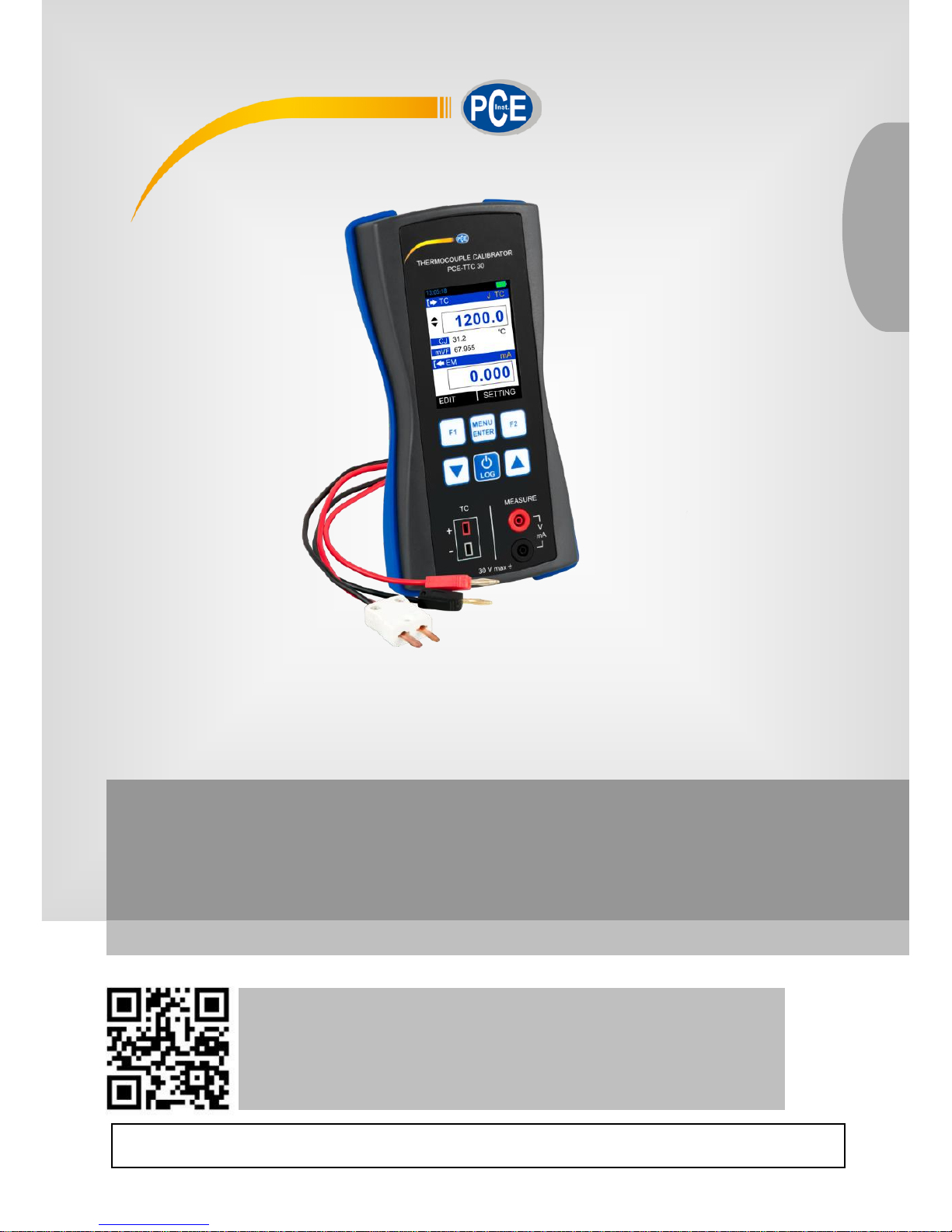
2.2 Operational Sections and Connections
All sections and connections are presented in detail on the next pages.
Note: Keep in mind that the next picture (as well as all pictures of the PCE-TTC 30 in this manual)
has an example configuration of modules. The configuration of your PCE-TTC 30 may vary
significantly from the one in the picture.
1 Terminal Connection for TC Measure and
Source
and EM Measure
2 Keypad Section
3 Color Display
4 USB Connection Slot for PC Communication
and
Charging
© PCE Instruments
4
2.2.1 Terminal Connections
EM Measure Terminals
Input Terminal for measuring voltage, current and supplying loop power.
EM Measure Terminals
mA
Range: 0.000 … 24.000 mA
Resolution: 0.001 mA
mA(24V)
Range: 0.000 … 24.000 mA
Resolution: 0.001 mA
V
Range: 0.000 … 30.000 V
Resolution: 0.001 V
Current Measurement
The PCE-TTC 30 supports current measurement using either PCE-TTC 30 as the loop power
supply while at the same time measuring the current or simply measuring the current while an
external power supply is used.
The following picture displays the connection for Current Measurement for different mode. And
also different ways of providing the supply power to the loop.
mA Current Measurement
In this mode, the PCE-TTC 30 does not provide any supply voltage. For proper measurement the
external device should capable of providing the voltage supply. If the external device should not
capable, an external Power Supply should be connected in series.
© PCE Instruments
5
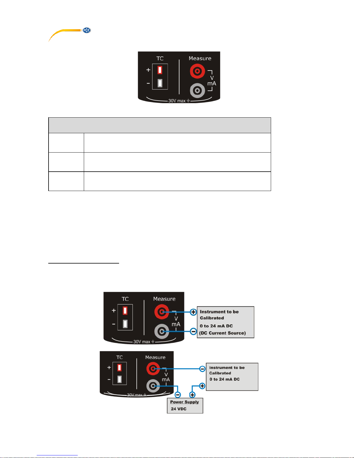
mA Read Power Current Measurement
In this mode, the PCE-TTC 30 works as Loop Power Supply while at the same time measuring
the current.
Voltage Measurement
The PCE-TTC 30 is capable of voltage Measurement with two voltage measurement ranges.
The following picture displays the connection for Voltage Measurement for different
mode.
TC Terminals
Terminal for measuring and simulating thermocouples and mV. This terminal accepts a
miniature polarized thermocouple plug with flat, inline blades spaced 7.9 mm (0.312 in)
center to center.
TC Terminal (Measure and Source)
TC Type
Range
Display
Resolution
Accuracy
E
-200.0 … 1000.0 °C
0.1 °C
± 0.3 °C
J
-200.0 … 1200.0 °C
0.1 °C
± 0.3 °C
K
-200.0 … 1372.0 °C
0.1 °C
± 0.3 °C
T
-200.0 … 400.0 °C
0.1 °C
± 0.3 °C
B
450.0 … 1800.0 °C
0.1 °C
± 0.5 °C
R
0.0 … 1750.0 °C
0.1 °C
± 0.5 °C
S
0 … 1750.0 °C
0.1 °C
± 0.5 °C
N
-200.0 … 1300.0 °C
0.1 °C
± 0.3 °C
mV
-10 … 80 mV
0.001 mV
+0.02 % of reading + 2µV
-10 … 250 mV
0.01mV
+0.02 % of reading + 0.02mV
The PCE-TTC 30 supports measurement and simulation of Thermocouple and mV.

© PCE Instruments
6
2.2.2 KeyPad
The PCE-TTC 30 has six different keys. The key description is given below.
This key has different functionalities in different menus.
These are shown in the bottom left part of the display.
This key has different functionalities in different menus.
These are shown in the bottom left part of the display.
- Scroll down to next parameter
- Decrease value of digit in Editbox
- Scroll down to previous parameter
- Increase value of digit in Editbox
- Enter menu when in Run mode
- Save edited parameter to memory
- Log current reading in memory if device is in Run mode and log mode
is manual
- When not in Run mode, this key is used to enter Run mode
- Press and hold (approx. 2 s) to turn meter on/off
© PCE Instruments
7
2.2.3 Display
• LCD with a 2.4” color display
• Resolution of 240x320 pixels
• Supporting 262K colors
2.2.4 USB Connection
• The USB connection is located at the top of the PCE-TTC 30. It is a USB mini B-Type female
connector.
• It can be used for PC communication and for charging the device.
• The USB cable supplied with the device is USB A-type male to USB B-type male. It is used
for connecting charger and PC.
2.2.5 Stand for Table Top Use
• This stand offers the best support for table top use which gives good viewing angle when
the PCE-LOC 20 is placed on a table.
• Procedure to open stand:
is being engraved on the top of the stand.
You should pull a bit first.
is being engraved on the bottom of the
stand. Now during first pull of above you
can release this lower part easily so that you
can
maneuver the stand as you like.

© PCE Instruments
8
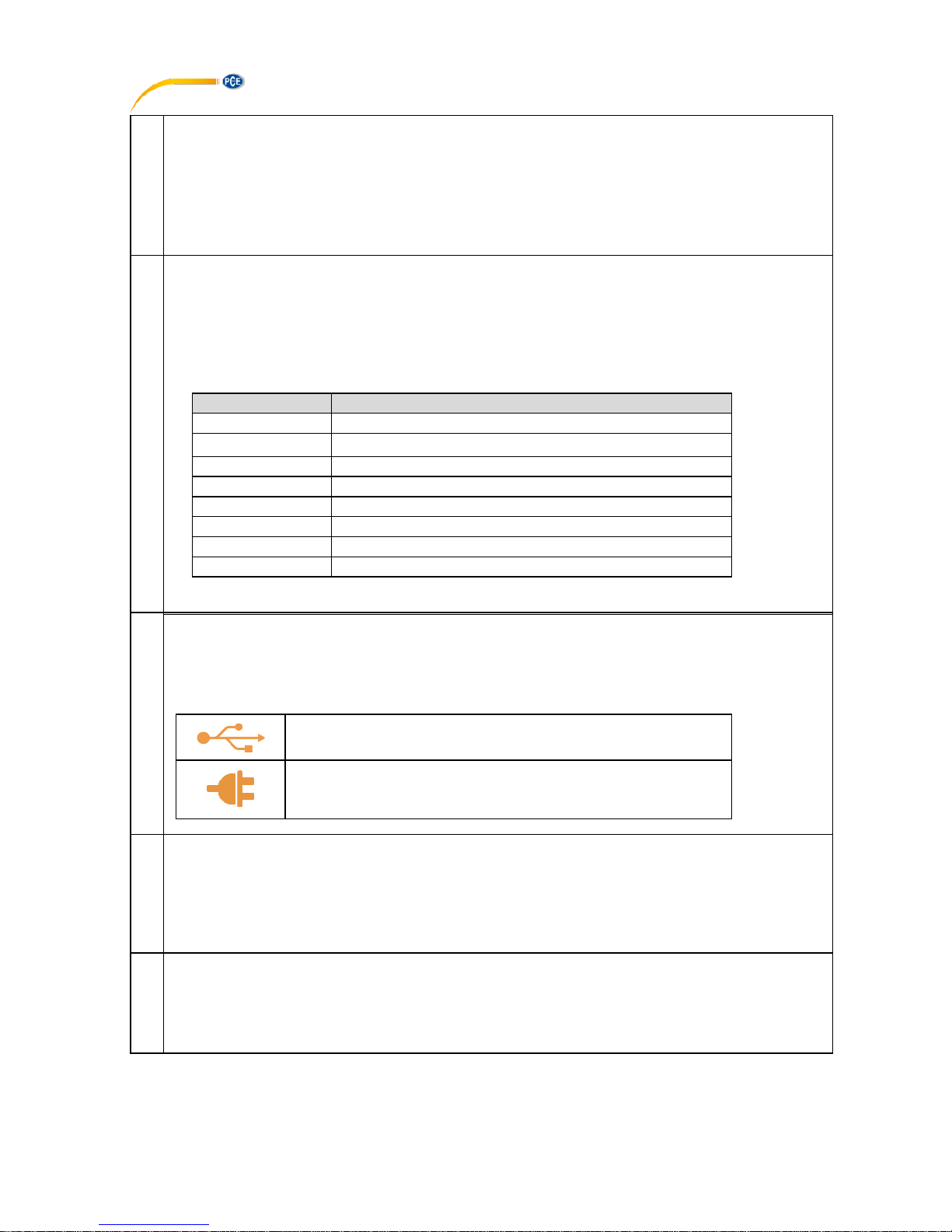
2.3 Power Options
There are three power options:
• Lithium-Ion battery: All the instrument functions are available with a charged battery.
• 5 V DC charging adaptor: It supplies power to the instrument and charges the battery at the
same time. It charges the battery when the instrument is on or off.
• USB mini Type B connection: This charges the battery when the instrument is off and
increases the battery life when the instrument is on.
2.4 Battery
The Device uses 2300mAh Lithium-Ion Battery. When you set the power on, the battery symbol
at the top of the display shows the charge status. To get more information on Battery go to Battery
Info Page in Setting Menu.
2.4.1 Charging time
Charging method
Charging time (to full capacity)
External Charging Adaptor
≈ 5 hours
Note:
USB mini Type B connector charges the battery when the instrument is off and increases the
battery life when the instrument is on.
2.4.2 Operating Time
Operation
Battery Duration
Continuous operation (measure or source)
>18 hours
Continuous operation (12mA (24V) measure)
> 8 hours
These are typical operating times for a new, fully charged Li-Ion battery pack with these
settings:
• Backlight Intensity set to 5% (Default: 100%)
• Backlight Timeout set to 0 (0=Infinite) (Default: 0)
Power save options: To get the best battery duration, set a low value for the Backlight Intensity
(40%) and a short Timeout.
The maximum operating time without recharging varies depending on the usage and brightness
setting of the display light. Also the generated output and the usage of the 24 V transmitter
supply affect the maximum operating time.

© PCE Instruments
9
Notes:
• The PCE-TTC 30’s memory and the internal clock/calendar use a small amount of
power although the calibrator is switched off. Remember to check the capacity of the
batteries from time to time although the PCE-TTC 30 is not in use.
• Do not leave the PCE-TTC 30 without a Battery Pack or an Empty Battery for a long
time. The PCE-TTC 30 may lose its settings if it is left without a support voltage for an
extended period.
3 Start Up and Basic Operations
3.1 Power On or Off
To set the instrument power ON, press and release this button down until the display comes on.
During the power on sequence, the instrument shows a Startup Message and then shows the
applicable data.
To set the instrument power off, press and hold (≈ 2 seconds) this button again. When the power
is off, the last set of configuration options stays in memory.
3.2 User Interface
Every time the PCE-TTC 30 is switched on, the startup message ends in RUN Page. 3 display
modes are available in RUN Page.
1. TC Measure/Source Mode
2. EM Measure Mode
3. TC Measure/Source + EM Measure Mode
This Display Mode can be selected from MENU→DISPLAY Page.
In case of Dual Mode Display Screen is divided into two parts. Due to that only few additional info
will appear on RUN Page. The information to be shown can be selectable in Display Mode Menu.
3.2.1 The Status Bar
The status bar at the top of the display is visible only in RUN Page. It is divided into five main
sections.
© PCE Instruments
10
1
Time in HH:MM:SS format
Available in two formats
1. 24 hour (default)
2. 12 hour
This setting is available in Date/Time in Settings Men
2
Error Code Indicator
This icon is visible if any on-board peripherals like RTC, ADC, DAC, etc. are not working
properly, see chapter 5 Maintenance and Troubleshooting.
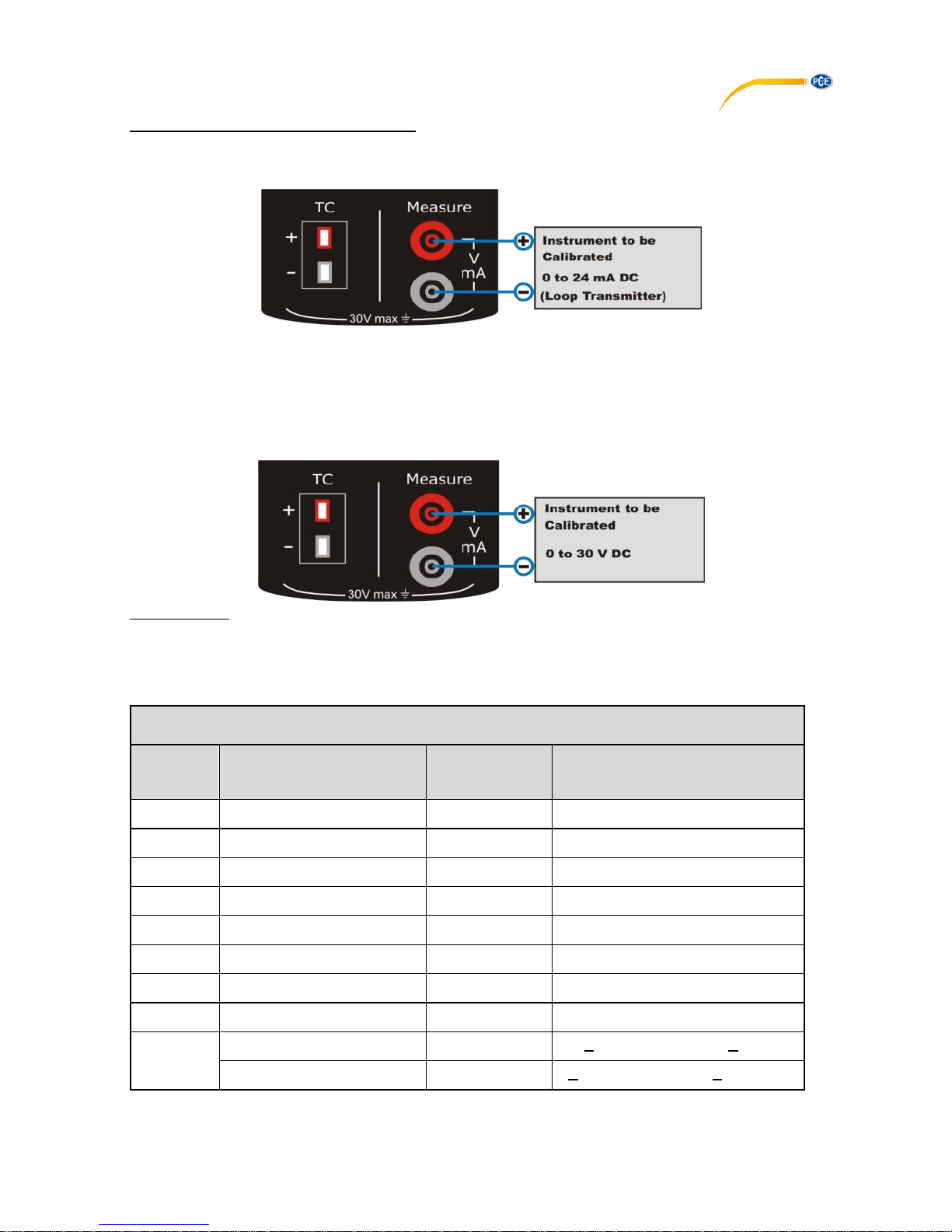
The List of error codes available in this device is given below.
Error code
Description
0
Memory corrupted or device unable to read/write it
1
RTC not working properly
2
Device unable to read battery information
3
Measure mode not working
4
Device unable to get source feedback reading
5
Data log memory corrupt
6
Source mode not working
9
More than one error from above list is occurring
3
USB Connection Status Icon
Icon is visible if USB charging adaptor or USB data cable is connected to the device. Icon
is different for both indications, see below.
USB data cable is connected and communication with PC
is available
USB charging adaptor is connected.
Battery starts charging.
4
Battery Charge Percentage Indicator
Always visible in Run page; battery % is shown in the centre of the icon and the icon
background is filled with green, yellow or red color if battery % is >= 50%, >= 20 and <20
respectively.
5
Data Logging Enable Status Indicator
Icon is visible if data logging is enabled and will flash when a data log is stored to the
memory
© PCE Instruments
11
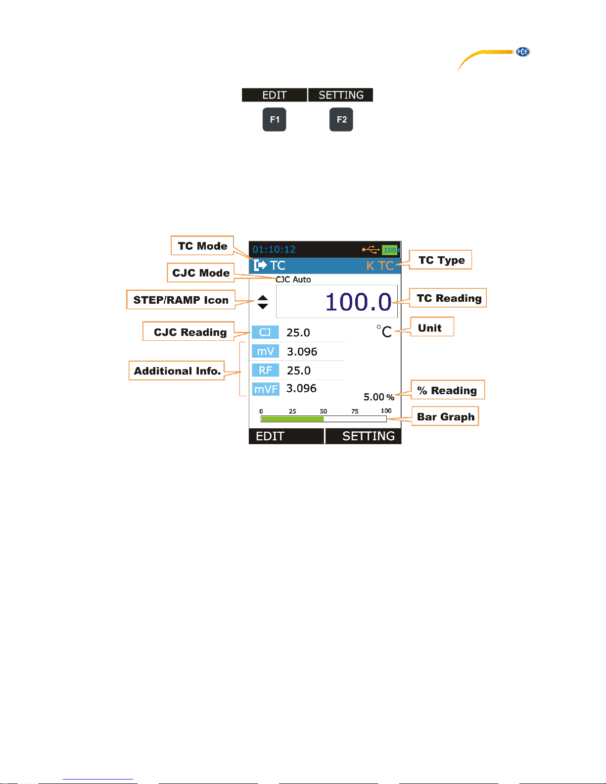
3.2.2 Function Key Bar
The function key bar at the bottom of the display is visible all the time. 2 function keys are
available. The meaning of the function keys varies depending on the situation. A blank function
key text means that the function is disabled at the moment.
3.2.3 Display Mode
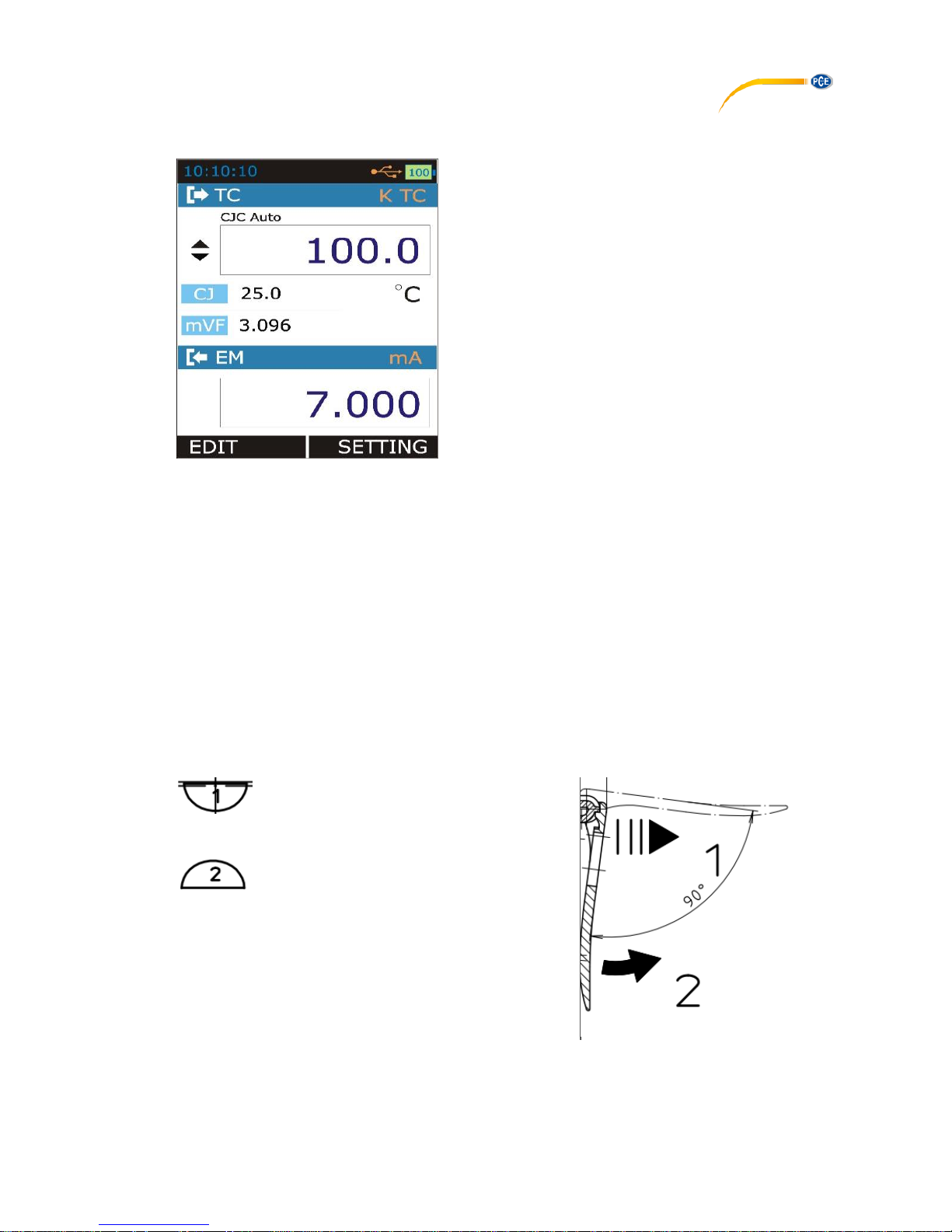
1. TC Mode
© PCE Instruments
12
TC Display Mode
TC Mode
Shows the Current Thermocouple Mode
TC Measure Mode
TC Source Mode
TCType
Shows the current Thermocouple/mV Type.
CJC Mode
Shows the CJC Mode
CJC Auto
CJC Auto Mode
CJC Manual
CJC Manual Mode
TC Reading
Shows the Thermocouple/mV Measure/Source reading according to display
mode and TC Type
Unit
Shows the Unit of the TC Reading, CJC
°C
Shows If TC Display mode is Actual and TC Unit is Celsius.
°F
Shows If TC Display mode is Actual and TC Unit is
Fahrenheit.
K
Shows If TC Display mode is Actual and TC Unit is Kelvin.
mV
Shows If TC Display mode is Actual.
And TC Type is -10 … 80 or -10 … 250mV.
%
Shows If TC Display mode is Percentage.
STEP/RAM
P Icon
Shows the Icon indicating STEP/RAMP mode. Only applicable if TC mode is
SOURCE.
Manual Step
Rising Ramp
Step UP
Falling Ramp
Step DOWN
Ramp Hold @ 0%
Ramp Hold @
100%
CJC
Reading
Shows the Temperature of the Cold Junction if CJC mode is selected as AUTO
and shows the user entered CJC Temperature value if CJC mode is MANUAL.
The Reading unit is same as TC Unit.
Additional
Info
Shows the Addition Information according to TC Mode and
Additional Info selected in MENU → DISPLAY → TC terminal.
© PCE Instruments
13
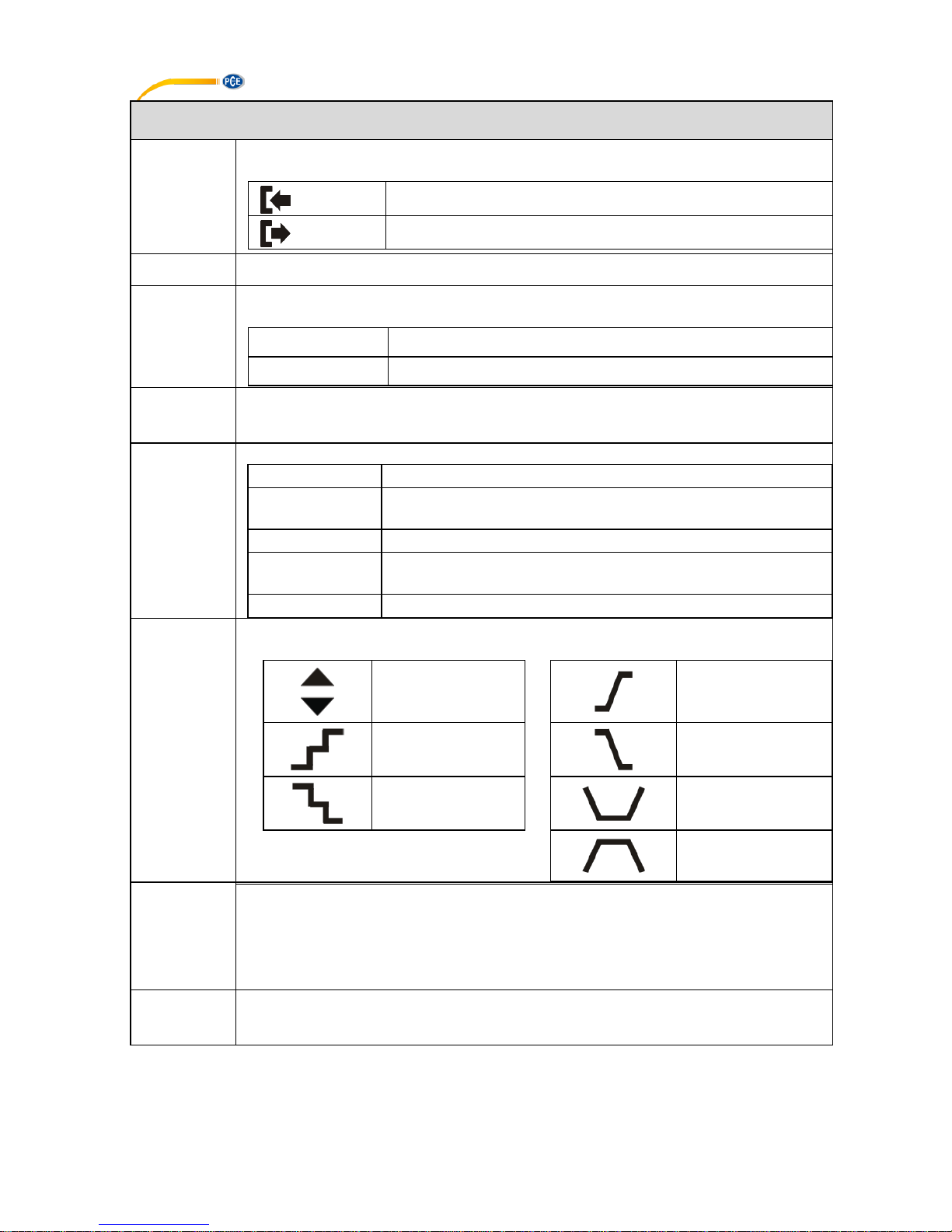
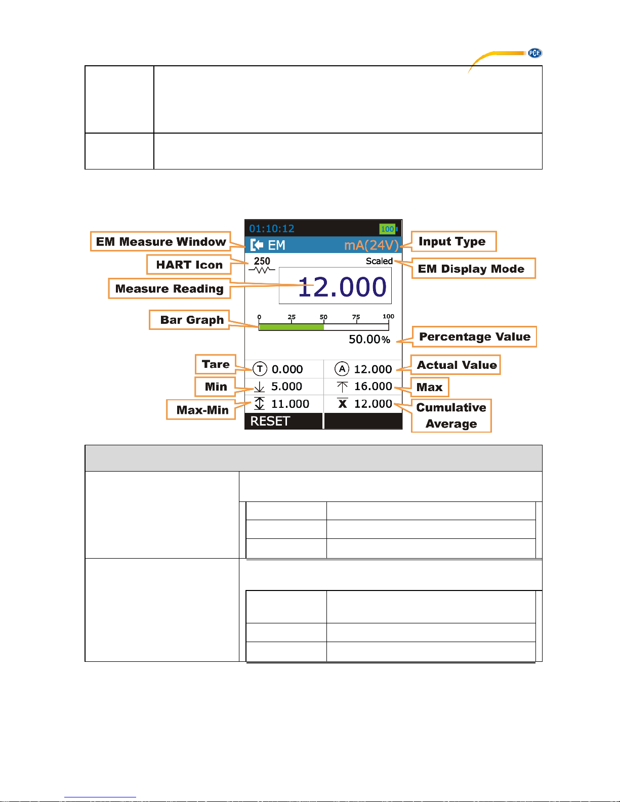
2. EM Measure Mode
Measure Window
Input Type
The Input Type.
mA
mA Current Input
mA(24V)
mA Current (Read Power-24V) Input
V
V Voltage Input
EM Display Mode
The Measure Reading Display Mode
Actual
Displays the Raw Input Value without any
scaling
Percentage
Displays the Percentage Value
Scaled
Displays the Scaled Value
Bar Graph
Horizontal Bar graph according to TC Percentage Value (0.00% -
100.00%). The value scales according to TC reading and Input 0% and 100%
value as set in MENU → DISPLAY → TC terminal Menu.
Percentage
Value
The Percentage Value in according to TC Reading.
 Loading...