

PCE Health and Fitness PCE-VE 700 Instructions For Use Manual
PCE Americas Inc.
711 Commerce Way
Suite 8
Jupiter
FL-33458
USA
From outside US: +1
Tel: (561) 320-9162
Fax: (561) 320-9176
info@pce-americas.com
www.pce-instruments.com/english
www.pce-instruments.com
PCE Instruments UK Ltd.
Southpoint Business Park
Hampshire / Southampton
United Kingdom, SO31 4RF
From outside UK: +44
Tel: (0) 2380 98703 0
Fax: (0) 2380 98703 9
info@industrial-needs.com
Instructions For Use
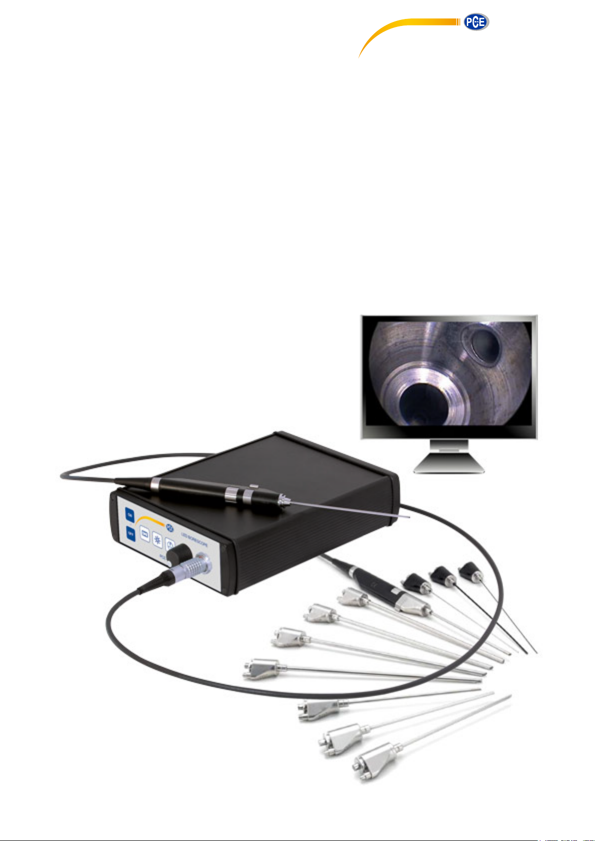
LED Industrial Endoscope PCE-VE 700
Visualization system for industrial endoscopy
Units 12/13
Ensign way

TPA500-PCE-00
Version: 0
2016 - Feb - 17
Instructions For Use LED BORESCOPE PCE-VE 700 | 17 - Feb - 2016 | Version: 0 Page 2 of 28

Content
0 Important Information About this Document....................................................................... 5
0.1 Scope of Validity, Identification, Purpose...................................................................................... 5
0.2 Target Group.................................................................................................................................. 5
0.3 Using and Storing this Document.................................................................................................. 5
1 General Information About the Device................................................................................. 6
1.1 Scope of Delivery...........................................................................................................................6
1.2 Intended Use.................................................................................................................................. 6
1.3 Safety Information.......................................................................................................................... 6
1.4 Device Description..........................................................................................................................7
1.4.1 Performance Characteristics and Function........................................................................7
1.4.2 Visual Overview..................................................................................................................8
1.5 Marking......................................................................................................................................... 11
1.5.1 Pictograms and Information on the Device and Packaging.............................................11
1.5.2 Information on the Nameplate......................................................................................... 11
1.6 Service Department Contact Details............................................................................................11
2 Use...........................................................................................................................................12
2.1 Handling Endoscopic Probes....................................................................................................... 12
2.2 Installation and Connecting the Power Supply............................................................................ 12
2.3 Connection of a Monitor...............................................................................................................13
2.4 Connection of a PC......................................................................................................................13
2.5 Connection of the Camera Head................................................................................................. 14
2.6 Connection of an Endoscopic Probe........................................................................................... 14
2.7 Switching On and Off...................................................................................................................15
2.8 Setting of the Window Size..........................................................................................................15
2.9 Image Focus.................................................................................................................................15
2.10 Setting of the White Balance........................................................................................................16
2.11 Setting of the Light Amplification on the Screen..........................................................................16
2.12 Conducting of Inspections............................................................................................................ 17
3 Cleaning.................................................................................................................................. 18
3.1 Cleaning of the Controller............................................................................................................ 18
3.2 Cleaning of the Camera Head and Cable................................................................................... 18
3.3 Cleaning of Endoscopic Probes...................................................................................................19
4 Maintenance and Repairs..................................................................................................... 20
4.1 Changing the Fuse.......................................................................................................................20
4.2 Troubleshooting Table..................................................................................................................21
4.3 Repairs..........................................................................................................................................23
Instructions For Use LED BORESCOPE PCE-VE 700 | 17 - Feb - 2016 | Version: 0 Page 3 of 28

5 Product Data.......................................................................................................................... 24
5.1 Technical Data..............................................................................................................................24
5.1.1 Controller.......................................................................................................................... 24
5.1.2 Camera Head................................................................................................................... 24
5.2 Ambient Conditions...................................................................................................................... 25
5.2.1 Transport and Storage Conditions................................................................................... 25
5.2.2 Operating Conditions....................................................................................................... 25
5.3 Spare Parts and Accessories.......................................................................................................25
6 Disposal.................................................................................................................................. 26
Instructions For Use LED BORESCOPE PCE-VE 700 | 17 - Feb - 2016 | Version: 0 Page 4 of 28

0 Important Information About this Document
0.1 Scope of Validity, Identification, Purpose
0 Important Information About this Document
0.1 Scope of Validity, Identification, Purpose
These instructions for use apply to the following device:
Description: LED BORESCOPE
Item numbers: PCE-VE 700
These instructions for use are an integral component of the device and contain all
the information required by users and operators for safe and proper use.
0.2 Target Group
These instructions for use are intended for all persons who are entrusted with the
operation and use of the product.
0.3 Using and Storing this Document
These instructions for use must be stored in a defined location so that they may
be accessed at all times by the target group.
In the event of the sale of this device or its relocation, this document must be
handed over to the new owner.
Instructions For Use LED BORESCOPE PCE-VE 700 | 17 - Feb - 2016 | Version: 0 Page 5 of 28

1 General Information About the Device
1 General Information About the Device
1.1 Scope of Delivery
The scope of delivery for the device includes:
one camera head with connection cable
one controller (CCU)
one external power supply with mains cable
one USB connection cable
one composite video cable
one S-video connection cable
one documentation software CD (test version)
one transport and storage case
one set of instructions for use
1.1 Scope of Delivery
Check scope of
delivery!
Check the delivery against the delivery note for completeness and damage.
The delivery left our premises in perfect condition. If you have any cause for com-
plaint, however, please contact our Service Department.
1.2 Intended Use
The PCE-VE 700 camera system is used for endoscopic inspection of industrial
components, such as injectors or hydraulic parts.
1.3 Safety Information
Our products are developed and manufactured to the highest quality standards.
Risks – despite the
high quality
Although this device corresponds to the current state of the art, risks could still
arise during initial operation, use, cleaning or maintenance.
Therefore, it is important that you read through these instructions for use carefully
and observe the warnings indicated.
The device must be operated only in a fault-free condition in accordance with the
intended use and the instructions for use. Before each use, check that the device
and accessories to be used are free of damage and in full working order.
Keep the original packaging. Transport and store the product in its original pack-
aging and use it to return goods if service support is required.
Routinely inspect all electrical equipment. Ensure that the electrical parts and con-
nections are undamaged. Replace the defective components and cables if need-
ed.
WARNING! Unauthorized modifications to the device. Risk of serious injury to
persons. Do not make any unauthorized modifications.
WARNING! Operating the device in an open condition. Risk of electric shock. Do
not open the device. Operate only when closed.
Instructions For Use LED BORESCOPE PCE-VE 700 | 17 - Feb - 2016 | Version: 0 Page 6 of 28

WARNING! High-intensity light source. Risk of injury to eyes. Do not look directly
into the light exit of the endoscope or of the camera head.
WARNING! Electrical connections installed improperly. Risk of fire, short circuit,
or electric shock. Make sure that the electrical connections are installed in accor-
dance with the relevant national technical regulations.
1.4 Device Description
1.4.1 Performance Characteristics and Function
1 General Information About the Device
1.3 Safety Information
Inspections in industrial
areas
Wide selection of
probes
Different image trans-
mission systems
The PCE-VE 700 camera system is a modular endoscopic visualization system
for use in industrial areas. The system consists of a camera head with integrated
LED light source and a camera controller.
A wide selection of rigid, semi-flexible and flexible endoscope probes is available
in different lengths and diameters for the camera system.
The brightness of the durable and maintenance-free LED can be continuously ad-
justed. The light is directed through optical fibers to the probe tip and is emitted
there into inspection area.
The probes are equipped with rod lens systems or quartz optical fiber bundles.
Probes with rod lens systems are distinguished by a high image quality and are
well-suited for straight boreholes. Probes with quartz fiber bundles are more flexi-
ble and permit the inspection of curved and very thin channels.
The image transmission system directs the image to the image sensor in the cam-
era head that converts the optical image into electrical signals. The controller re-
ceives and renders them on the monitor.
A connected PC with appropriate software enables the capture of videos and stat-
ic images. An additional video output permits the connection of further peripherals
such as printers, recorders or frame grabbers.
Instructions For Use LED BORESCOPE PCE-VE 700 | 17 - Feb - 2016 | Version: 0 Page 7 of 28
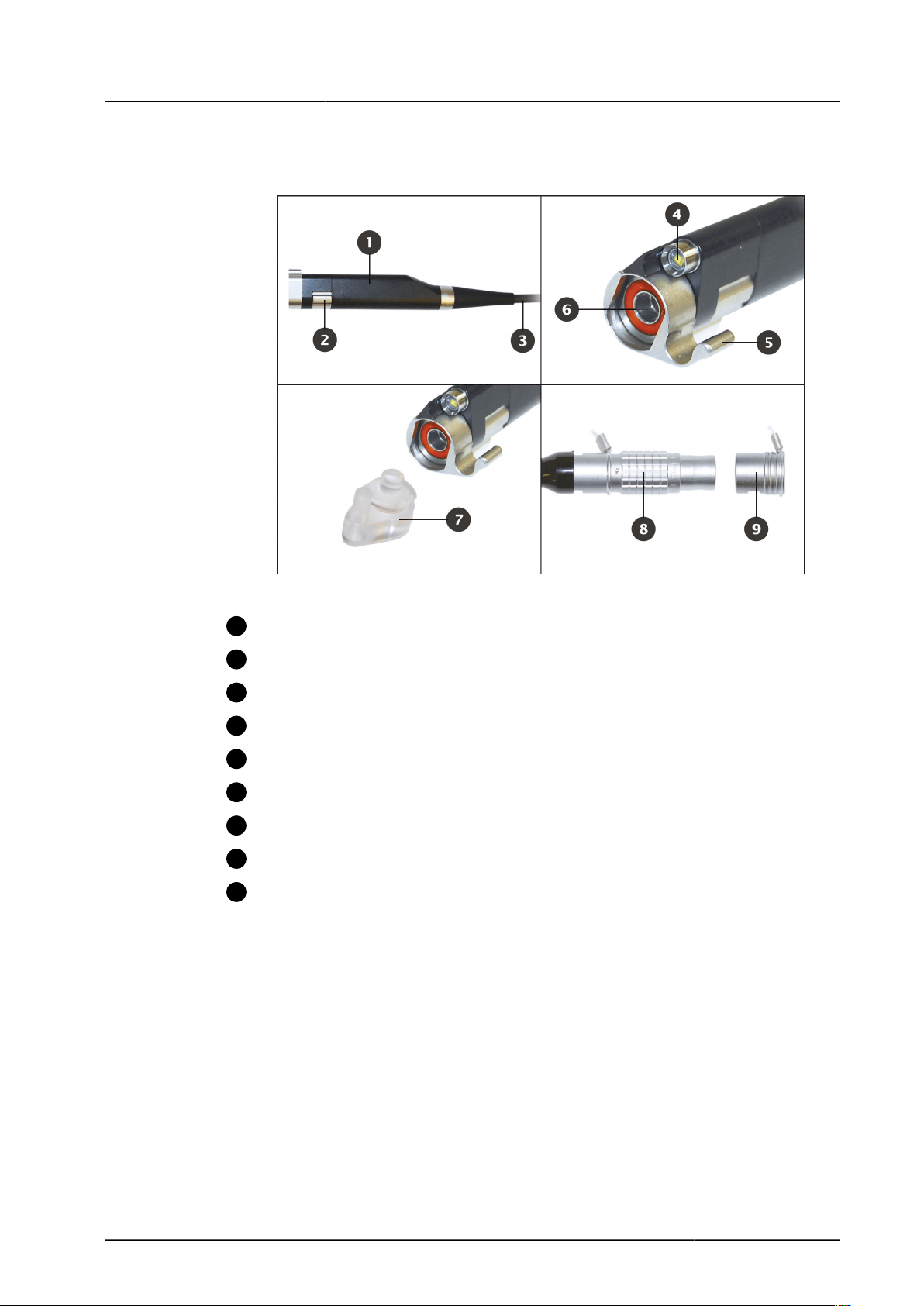
1.4.2 Visual Overview
1
2
3
4
5
6
7
8
9
Camera Head
1 General Information About the Device
1.4 Device Description
Figure 1-1: Camera head.
Camera head
Focusing
Controller (CCU) connection cable
LED light source
FlexiLock Lock for interchangeable probes
Front glass panel
Protective cap
Connection plug
Connection cap
Instructions For Use LED BORESCOPE PCE-VE 700 | 17 - Feb - 2016 | Version: 0 Page 8 of 28
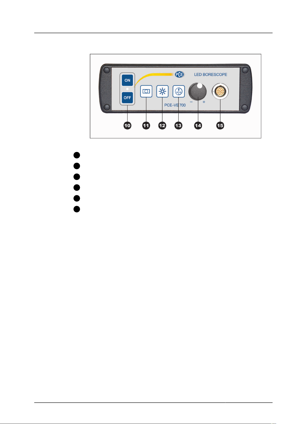
Controller - Front View
10
11
12
13
14
15
1 General Information About the Device
1.4 Device Description
Figure 1-2: Front view of the controller.
ON/OFF switch
Window function
Gain control
White balance
LED brightness control
Socket for the connection cable on the camera head
Instructions For Use LED BORESCOPE PCE-VE 700 | 17 - Feb - 2016 | Version: 0 Page 9 of 28
 Loading...