

PCE Health and Fitness PCE-FWS 20 User Manual

www.pce-industrial-needs.com
Tursdale Technical Services Ltd
Unit N12B
Tursdale Business Park
Co. Durham
DH6 5PG
United Kingdom
Phone: +44 ( 0 ) 191 377 3398
Fax: +44 ( 0 ) 191 377 3357
info@tursdaletechnicalservices.co.uk
htt
p
://www.industrial-needs.com/
Manual
Touch Screen Weather Station
PCE-FWS 20

info@tursdaletechnicalservices.co.uk
2
Manual ..................................................................................................................................... 1
Touch Screen Weather Station ................................................................................................ 1
PCE-FWS 20 ........................................................................................................................... 1
Operation Manual .................................................................................................................... 3
About this manual .................................................................................................................... 3
Glossary of Common Terms .................................................................................................... 3
DCF/WWVB ......................................................................................................................... 3
LCD ...................................................................................................................................... 3
BAROMETER & BAROMETRIC PRESSURE ..................................................................... 3
RELATIVE AIR PRESSURE ................................................................................................ 3
ABSOLUTE AIR PRESSURE .............................................................................................. 3
INCHES OF MERCURY (inHg) ............................................................................................ 3
HECTOPASCALS ................................................................................................................ 3
Getting Started ........................................................................................................................ 4
Setup Sensors ..................................................................................................................... 5
System Start ............................................................................................................................ 7
Positioning ............................................................................................................................... 8
Setting Up ................................................................................................................................ 8
indoor temperature ............................................................................................................... 8
outdoor temperature ............................................................................................................. 9
Indoor humidity .................................................................................................................. 10
Outdoor humidity ................................................................................................................ 11
Wind speed ........................................................................................................................ 11
Rain .................................................................................................................................... 12
Weather forecast ................................................................................................................ 13
Pressure ............................................................................................................................. 13
Pressure bar graph ............................................................................................................ 14
Time ................................................................................................................................... 14
Date ................................................................................................................................... 15
Memory .............................................................................................................................. 16
PC Connection ...................................................................................................................... 16
Data Storage ...................................................................................................................... 16
Data Recall ........................................................................................................................ 16
Connections and Software ................................................................................................. 16
PC software installation ......................................................................................................
... 16
Specifications ........................................................................................................................ 18
Outdoor data ...................................................................................................................... 18
Indoor data ......................................................................................................................... 19
PC Software User Manual ..................................................................................................... 19
General Information ............................................................................................................... 19
System Requirements ........................................................................................................... 20
Installation of the “EasyWeather” Software ............................................................................ 20
Basic Settings of the “EasyWeather” Software ...................................................................... 21
Function button: ................................................................................................................. 22

info@tursdaletechnicalservices.co.uk
3
Operation Manual
About this manual
Thank you and congratulations on selecting this professional weather station! We are
positive you will enjoy the benefits of accurate weather readings and the precise radio
controlled time information that our instruments offer.
This manual will guide you step-by-step through setting up your PCE-FWS 20 device. Use
this manual to become familiar with your professional weather station, and save it for future
reference.
Glossary of Common Terms
DCF/WWVB
The DCF or WWVB time signal is an AM modulated time-of-day signal broadcasted by the
Federal Government of Germany or NIST from USA. The time base is generated from an
atomic time generator which is accurate to 10 billions of one second.
LCD
“LCD” is an acronym for ”Liquid Crystal Display”. This is a common type of display screen
used in televisions, computers, watches, and digital clocks.
BAROMETER & BAROMETRIC PRESSURE
A barometer is a device that measures the pressure of the air pushing on it—this
measurement is called the barometric pressure. We don’t actually feel the barometric
pressure because the air pressure is pushing equally in every direction.
RELATIVE AIR PRESSURE
Relative air pressure is the same as the barometric pressure. The calculation of relative air
pressure is a combination of the absolute air pressure and the altitude.
ABSOLUTE AIR PRESSURE
Absolute air pressure is the actual air pressure on the barometer without regard to altitude.
INCHES OF MERCURY (inHg)
Inches of Mercury is the common unit of measurement for air pressure in the United States.
HECTOPASCALS (hPa)
Hectopascals are the common units of measurement for air pressure in the International
System (SI) of measurement. The hectopascal holds the same value Important Note:
Before inserting batteries, please carefully read the operation manual.
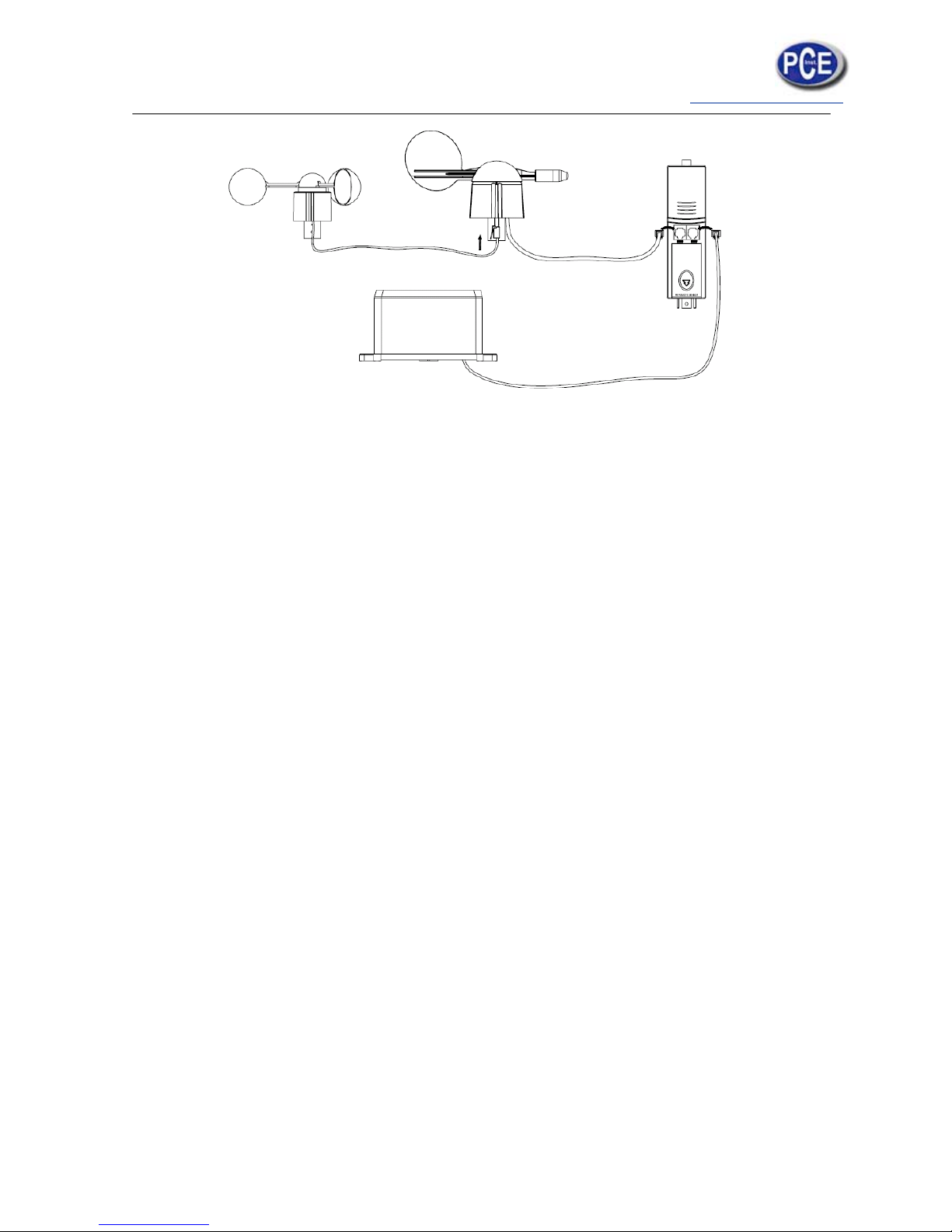
The touch screen weather station PCE-FWS 20 includes a base station (receiver), a
transmitter unit, one wind direction sensor, one wind speed sensor, one rain gauge, USB
cable and a PC software package on CD-ROM.

info@tursdaletechnicalservices.co.uk
4
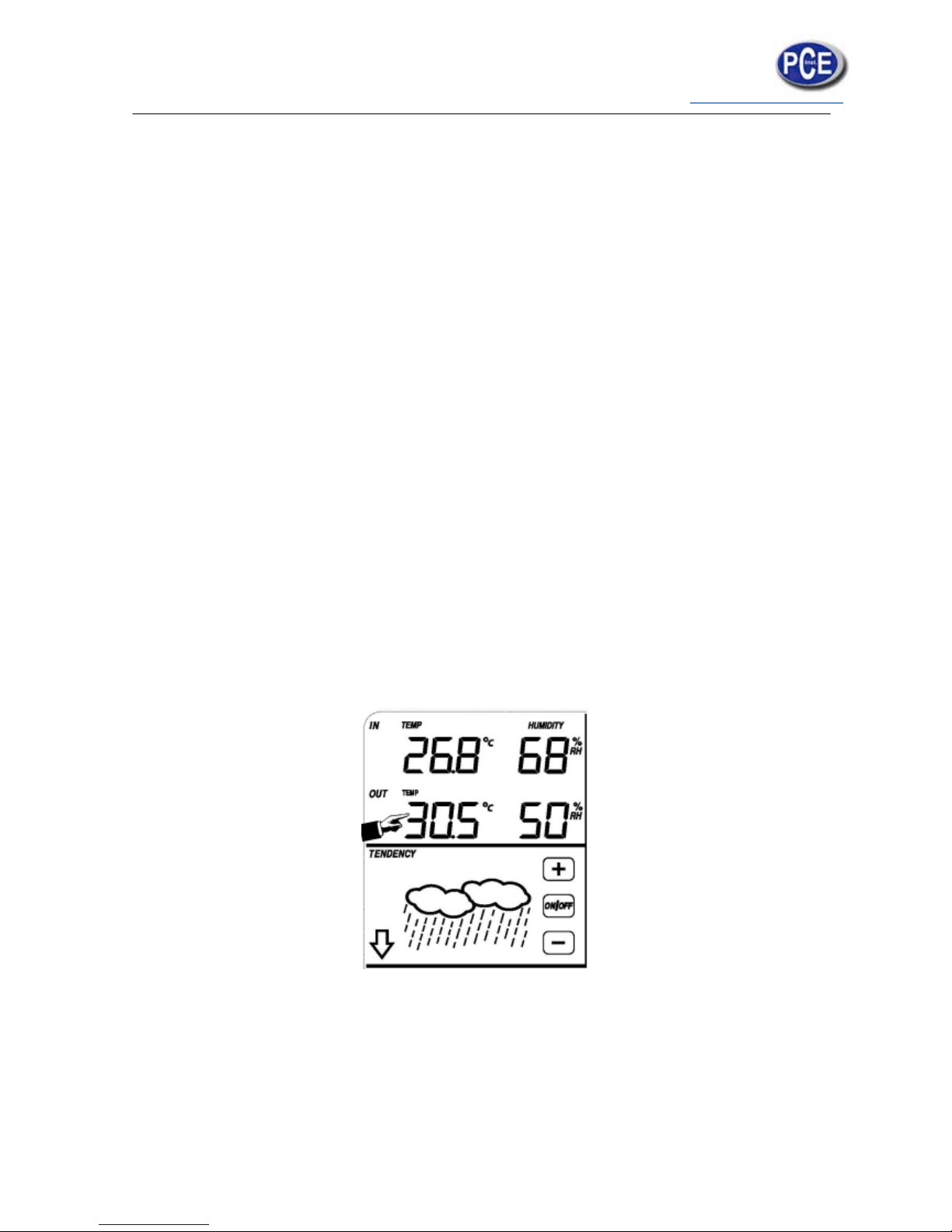
The Base Station is equipped with a Touch Screen LCD Monitor and allows the display of a
large variety of time and weather data.
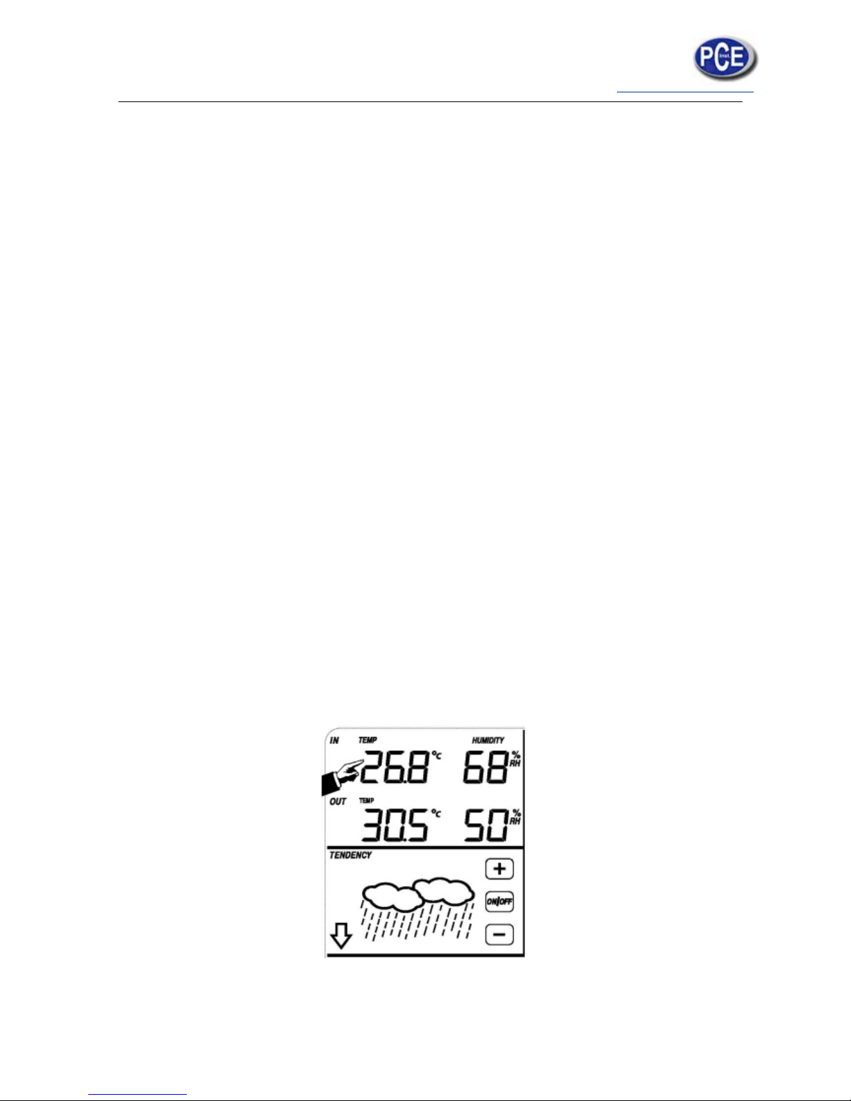
Left Top LCD: IN-OUT temperature and humidity
Right Top LCD: Wind and Rain measurement
Left Middle LCD: Weather Forecast (Tendency)
Right Middle LCD: Air Pressure and Air Pressure History
Bottom Line LCD: Time and Date, Memory Data Usage
Note: The presence of the "Alarm-On icon" in the section means that the particular alarm has
been enabled.
An added feature of the Weather Station is the readout of all measured and displayed
time and weather data on a PC as well as the ability to upload the data to Internet Web
Sites.
Important Operation Notes
All actions and functions of the weather station are started on the touch screen by slightly
Touching (not pressing!) the related areas, touch the flashing +, ON/OFF or – to make the
corresponding selection or increase the value.
Every time a programming step is activated by touching a switching area on the Touch
Screen a tone will sound, and the back light is switched on for a few seconds as well.
If no areas are pressed for 30 seconds, the LCD will automatically revert to the normal
display mode (automatic time out).
Getting Started
info@tursdaletechnicalservices.co.uk
5
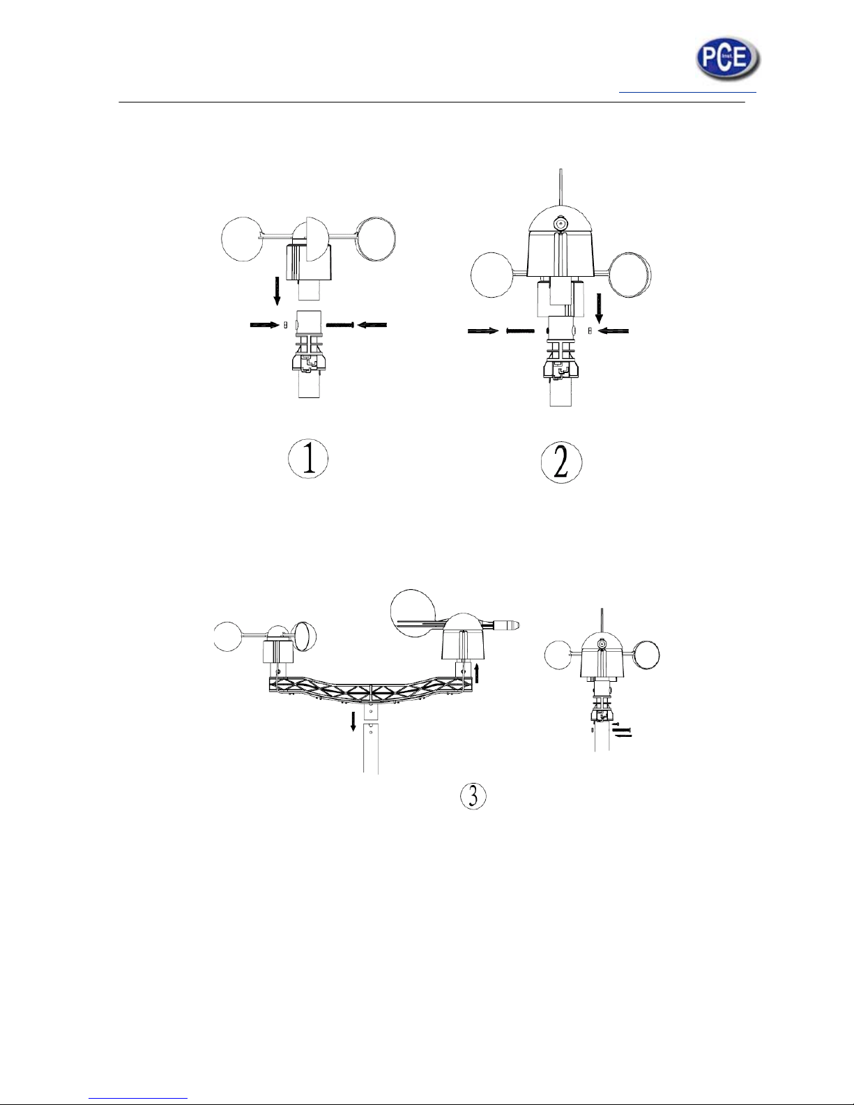
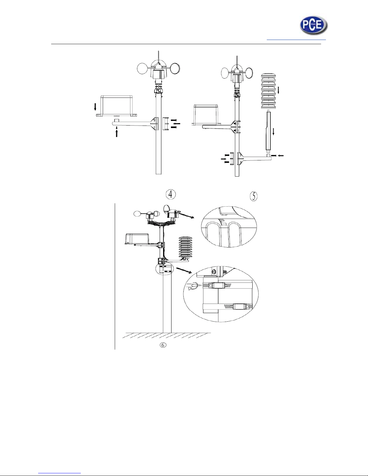
Setup Sensors
info@tursdaletechnicalservices.co.uk
6
info@tursdaletechnicalservices.co.uk
7
Important Notes:
On the edge of wind direction sensor, there are four alphabet letter of “N”,”E”,”S” and “W”
representing for the direction of North, East, South and West. Wind direction sensor has to
be adjusted so that the directions on the sensor are matching with your real location.
Permanent wind direction error will be introduced when the wind direction sensor is not
positioned correctly during installation.
Wind speed sensor wire has to be inserted into the phone jacket on wind direction sensor.
Wind direction sensor wire has to be inserted into the phone jacket located on the thermohygro sensor with marking of “Wind” on top.
The rain sensor wire has to be inserted into the phone jacket located on the thermo-hygro
sensor with marking of “Rain” on top.
System Start
Insert two pieces of LR6 (AA size) batteries into the transmitter, the LED located in the
middle front case of transmitter will be turned on for 4 seconds and then it will be off and start
to work normally. The transmitter will make a data transmission and then start radio
controlled time reception routine. If time signal can be detected correctly, then the LED will
start to flash 5 times indicating time signal has been found correctly. When time signal is bad
and reception is not possible, the transmitter will terminate radio controlled time reception
within one minute and resume normal mode. When there is a data transmission happened,
the LED will be on for 20ms. During radio controlled time reception period, there is no
transmission and normal transmission will only resume after time reception routine is
complete. The longest time for radio controlled time reception is 5 minutes.
After inserting the batteries into the Weather Station, all LCD segments will be turned on for a
few seconds, all possible display segments are turned on for checking.
After this, the weather station will make initial measurement and start to register the
transmitter ( the radio reception icon will be turned on). Before there is outdoor data received,
it is not allowed to touch the LCD, otherwise the outdoor sensor learning mode will be
terminated right after the touch of LCD. When outdoor transmitter has been registered, the
Touch Screen Weather Station will automatically switch to the normal display mode from
which all further settings can be performed by the user.
info@tursdaletechnicalservices.co.uk
8
If no RCC signal is detected in the initial setup, the transmitter will try once every hour to get
an RCC signal until a signal is received. Once the transmitter receives the RCC signal it will
transmit the signal to the monitor.
On the monitor the RCC icon will be displayed, if the monitor doesn’t receive the RCC signal
or loses the signal the RCC icon will not be display.
Note: The best condition for reception is at night, between midnight and 6:00am – when
there is less atmospheric interference.
Positioning
Once you have verified that all of the components of the weather station are working, they
can be positioned in their permanent places. Before permanently mounting, make sure that
all components work properly together at their chosen mounting or standing locations. If e.g.
there appear to be problems with the 868 MHz radio transmission, they can mostly be
overcome by moving the mounting locations.
Note: Commonly the radio communication between receiver and transmitter in the open field
can reach a distance of up to 330 feet providing that there are no interfering obstacles such
as buildings, trees, vehicles, high voltage lines, etc.
Radio interferences such as PC screens, radios or TV sets can, in bad cases, entirely cut off
radio communication. Please take this into consideration when choosing standing or
mounting locations.
Setting Up
Note: Because of the default set tings already determined by the manufacturer it may not be
necessary for the majority of users to perform – except the Relative Air Pressure (see further
down) - any further basic settings. Changes, however, can be easily made.
For basic settings, the following menu is started by touching the Touch Screen in the desired
display area.
The basic settings can now be performed in the following successive order:
Note: setting procedure can be exited at any time by touching any other function area (except
“+”, “-” or “ON/OFF”).
indoor temperature
info@tursdaletechnicalservices.co.uk
9
Activate the indoor temperature related setting by
1) Touch the INDOOR TEMPERATURE section, + button and – button will be flashing.
Touch the + button or – button to Shift the display unit between C and F
2) Touch the INDOOR TEMPERATURE section again to set the indoor temperature high
alarm function, the +, ON/OFF and – button will be flashing, HI AL icon will light up. Touch
the + button or – button to change the value, hold the + button or – button for 3s to change
the number in great step. Touch the ON/OFF button to choose the alarm on or off (if alarm is
enabled, the speaker icon will be turned on indicating the alarm function has been enabled).
3) Touch the INDOOR TEMPERATURE section the third time to set the indoor temperature
low alarm function, the +, ON/OFF and – button will be flashing, LO AL icon will light up.
Touch the + button or – button to change the value, hold the + button or – button for 3s to
change the number in great step. Touch the ON/OFF button to choose the alarm on or off (if
alarm is enabled, the speaker icon will be turned on indicating the alarm function has been
enabled).
4) Touch the INDOOR TEMPERATURE section the fourth time to display maximum indoor
temperature record, the maximum records will be flashing, MAX icon will light up as well.
Hold the flashing max value for 3s, the maximum value will be reset to current reading.
5) Touch the INDOOR TEMPERATURE section the fifth time to display minimum indoor
temperature record, the minimum records will be flashing, MIN icon will light up as well. Hold
the flashing min value for 3s, the minimum value will be reset to current reading.
outdoor temperature
Activate the outdoor temperature related setting by
1) Touch the OUTDOOR TEMPERATURE section, + button and – button will be flashing.
Touch the + button or – button to Shift the display between Outdoor Temperature, Wind Chill
and Dew Point.
2) Touch the OUTDOOR TEMPERATURE section again, + button and – button will be
flashing. Touch the + button or – button to Shift the display unit between C and F
 Loading...