

PCE Health and Fitness PCE-CSM 2X Series, PCE-CSM 20, PCE-CSM 21, PCE-CSM 22 User Manual
English
User Manual
Spectrophotometer PCE-CSM 2X Series
User manuals in various languages (français, italiano, español, português,
nederlands, türk, polski, русский, 中文) can be found by using our
product search on: www.pce-instruments.com
Last change: 2 March 2018 v1.0
© PCE Instruments

INSTRUCTION ............................................................................................................................. 1
CAUTIONS .................................................................................................................................... 1
1. INTERFACE DESCRIPTION ................................................................................................... 2
2. OPERATING INSTRUCTION .................................................................................................. 4
2.1
POWER ON & OFF ........................................................................................................................... 4
2.2
CALIBRATION .................................................................................................................................. 5
2.3
MEASUREMENT ............................................................................................................................... 7
2.3.1 Measurement Instruction ........................................................................................................ 7
2.3.2 Standard Measurement .......................................................................................................... 9
2.3.3 Sample Measurement ........................................................................................................... 12
2.3.4 Average Measurement .......................................................................................................... 14
2.4
CONNECTING TO PC ...................................................................................................................... 15
2.4.1 USB Connection ..................................................................................................................... 16
2.4.2 Bluetooth Connection ............................................................................................................ 16
3. MAIN MENU ........................................................................................................................... 18
3.1
DATA MANAGEMENT ..................................................................................................................... 18
3.1.1 Check Record ......................................................................................................................... 18
3.1.2 Delete Record ........................................................................................................................ 23
3.1.3 Search Record ........................................................................................................................ 24
3.1.4 Standard Input ....................................................................................................................... 27
3.2
CALIBRATION ................................................................................................................................ 29
3.3
AVERAGE ....................................................................................................................................... 30
3.4
LIGHT SOURCE .............................................................................................................................. 30
3.5
COLOR SPACE ................................................................................................................................ 32

GRATING SPECTROPHOTOMETER OPERATING MANUAL
3.6 COLOR INDEX ................................................................................................................................ 33
3.6.1 Set Color Index ....................................................................................................................... 33
3.6.2 Parameter Factors Settings ................................................................................................... 35
3.7
DISPLAY SETTING .......................................................................................................................... 38
3.8
SYSTEM SETTING .......................................................................................................................... 39
3.8.1 Auto Save .............................................................................................................................. 40
3.8.2 Measurement Aperture ......................................................................................................... 40
3.8.3 Bluetooth ............................................................................................................................... 41
3.8.4 Buzzer Switch ......................................................................................................................... 42
3.8.5 Sample Measurement Mode ................................................................................................. 42
3.8.6 Calibration Validity ................................................................................................................ 43
3.8.7 Control Mode ......................................................................................................................... 44
3.8.8 Language Setting ................................................................................................................... 45
3.8.9 Time Setting .......................................................................................................................... 46
3.8.10 Backlight Time ..................................................................................................................... 47
3.8.11 System Tolerance ................................................................................................................. 47
3.8.12 Screen Brightness ................................................................................................................ 47
3.8.13 Restore Factory Settings ...................................................................................................... 48
4. DAILY MAINTENANCE ......................................................................................................... 48
5. TECHNICAL PARAMETERS ................................................................................................. 49
5.1
PRODUCTS FEATURES .................................................................................................................... 49
5.2
TECHNICAL SPECIFICATIONS ......................................................................................................... 50
2

Instruction
The PCE- 2X Series series grating spectrophotometer are sold by the PCE
company, who has complete intellectual property rights. The instrument
has the character of stable working, accurate color measurement,
powerful functions, and take the leading position in the color industry.
They are widely used in plastic, electronics, paints, textile, printing,
automobile, medical, cosmetic and food industries or science research
institutes and laboratories.
With the D/8 geometric optical illumination recommended by CIE, the
instruments can measure SCI / SCE reflectance data of sample or
fluorescent sample, and can measure and indicate all color difference
formulas and color indexes in various of color spaces accurately. By
using the instruments, it is easy to achieve the accurate color transmission,
the instruments also can be accurate measuring equipment for color
matching system and widely used in color quality control area. The
instruments are equipped with high-end color management software
which can be connected to PC to achieve more extension functions.
Cautions
● The spectrophotometer is a precise measuring instrument. Please avoid
drastic changes of external environment when measuring. These changes,
including the flicker of surrounding light and the rapid change of
temperature, will affect measurement accuracy.
● Keep the instrument balanceable; make sure the measuring aperture
touch the surface of the test sample placidly, and no shaking or shifting
when measuring. Please prevent the colorimeter from fierce collision or

GRATING SPECTROPHOTOMETER OPERATING MANUAL
crash.
● The instrument is not waterproof. Do not use it in high humidity
environment or in water.
● Keep the instrument clean. Avoid dust, powder or solid particles
entering the measuring aperture and the instrument.
● Replace the white calibration cavity and put the spectrophotometer into
instrument case when not in use.
● Please take out the battery to prevent the instrument from damage if
you don’t use it for a long time.
● Please keep the instrument in a cool dry place.
● Any unauthorized changes to the instrument are not permitted, or it will
affect the measuring accuracy, even cause irreversible damage.
1. Interface Descripti o n
Indicator Light
TFT LCD screen
Testing Button
Aperture
Aperture Switch
Power Switch
DC Power port /
USB port
Figure 1 Instrument Structure Diagram
2

GRATING SPECTROPHOTOMETER OPERATING MANUAL
Port Description
1. Power Switch 1/0: Push the switch to “1” to turn on the instrument.
Push the switch to “0” to turn it off.
2. Switch / Testing button: Long press for 3 seconds to turn ON/OFF
power, short press for measurement.
3. Indicator light: LED light includes green, yellow and red.
* Turn to red when battery in charge and turn to green when battery is
full.
* Without doing black/white calibration or out of validation, LED light
turns to red when switching on the instrument and measurement could not
be performed.
* LED light turns to yellow during measuring and turns to green when
finished. If during measurement the instrument shocked or measuring
data abnormal, it turns to red when finished and the measuring date needs
to be checked.
* LED light turns to yellow when doing the black/white calibration, and
turns to green for calibration succeeded, to red for calibration failed.
4. DC Power Port / USB / : A common interface. The
instru
ment w
ill judge the connection status automatically. DC Power Port
to connect with AC adapter for charging. The adapter specification is 5V,
2A. USB port is used to transfer data to PC.
5. Aperture switch: used for changing the measuring aperture, setting
this switch to “MAV”, turn to Φ8mm aperture, while setting this switch to
“SAV”, turn to Φ4mm aperture.
3
GRATING SPECTROPHOTOMETER OPERATING MANUAL
2. Operating Instruction
2.1 Power On & Off
The instrument supports both hard power on & off and soft power on &
off. As per Figure 1, Setting power switch to “0” turns the power OFF,
and setting it to “1” turns the power ON. The instrument will enter into
soft turn off after long time no operation (Please look into chart 3.8.10 for
backlight time), press “Power/Test” button for 3 seconds to turn on. Press
“Power/Test” button for 3 seconds to soft turn off the instrument.
After the instrument turns on, it will enter into the display as show in
Figure 2 if the black/white calibration is out of validation or the turn-on
calibration is set. Or it will enter into the display as show in Figure 3 to
measurement interface.
Figure 2 White and Black Calibration
4
GRATING SPECTROPHOTOMETER OPERATING MANUAL
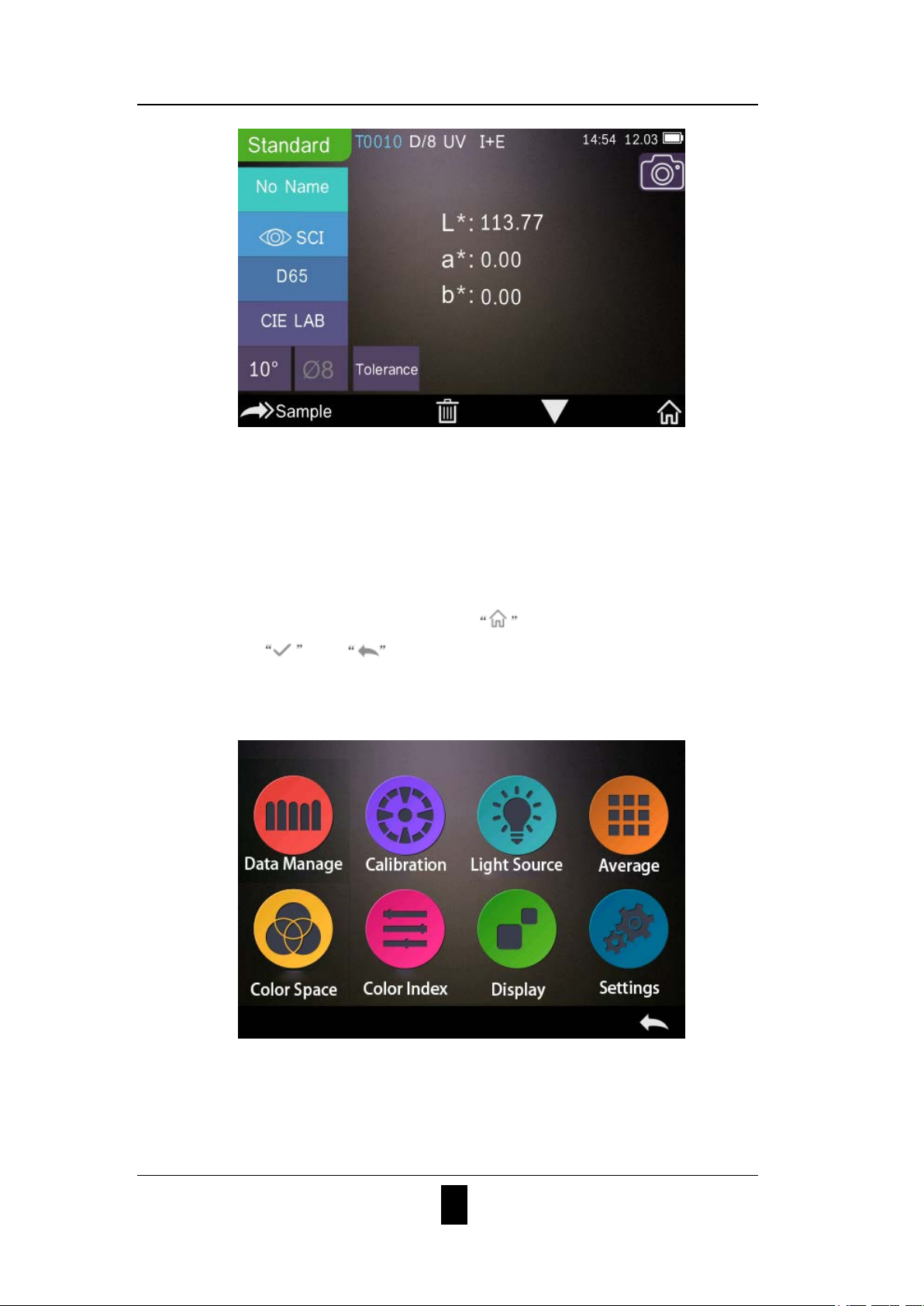
Figure 3 Standard Measurement
2.2 Calibration
In the measurement interface, click to enter main menu, others
please click or to enter main menu, as shown in Figure 4.
Figure 4 Main Menu
5
GRATING SPECTROPHOTOMETER OPERATING MANUAL
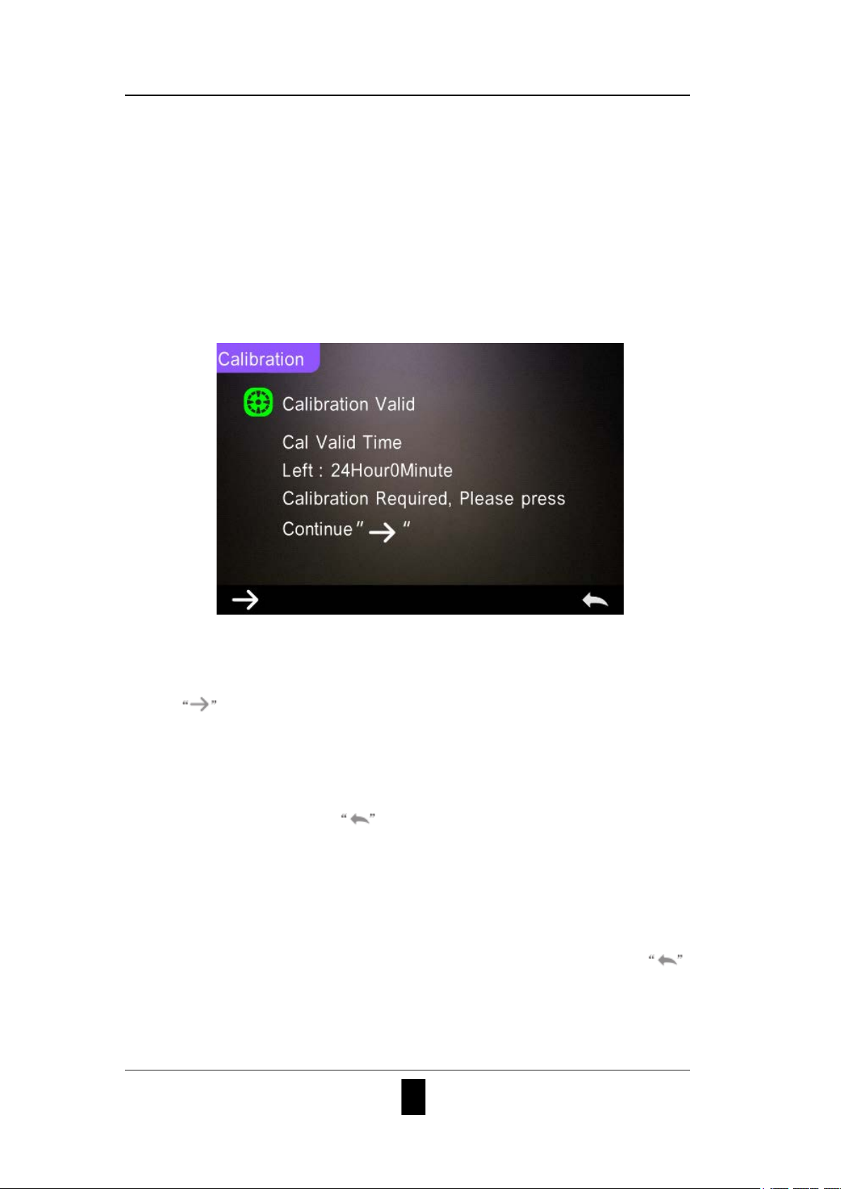
Select “Calibration” to enter white and black calibration interface as
shown in Figure 5.
It will show if the calibration is valid or not, and the remaining time if it
is valid.
Figure 5 White and Black Calibration
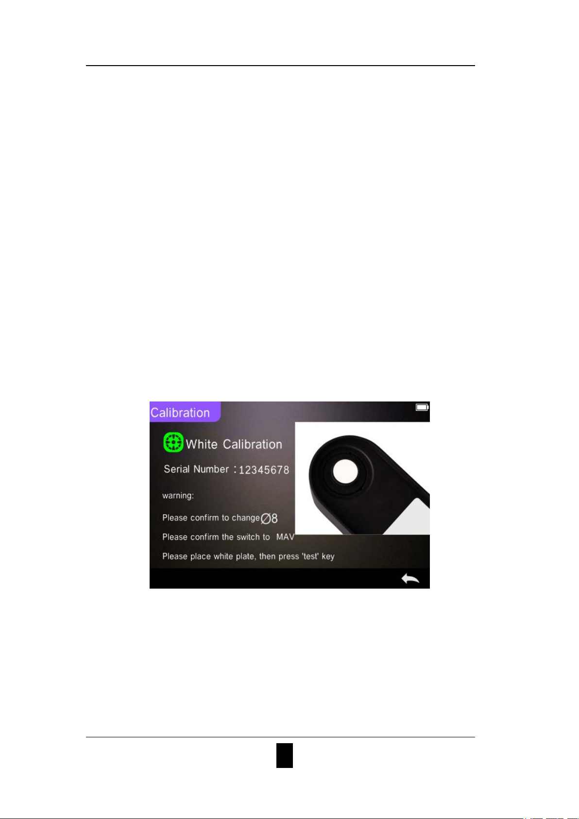
Click to continue and enter “White Calibration” as shown in Figure
2. According to warning, confirm the serial number of white calibration
plate correspond to the instrument and correct aperture setting, then put
the measuring aperture on white board and press “Testing” button for
white calibration, or click to cancel and quit the calibration.
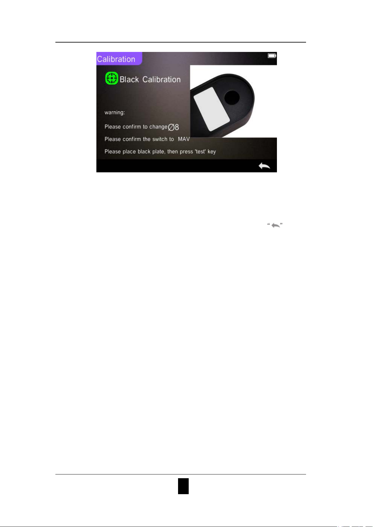
After white calibration, it will prompt you to black calibration as shown
in Figure 6. According to warning, put the measuring aperture on black
board and press “Testing” button for black calibration, or click to
cancel and quit the calibration.
6
GRATING SPECTROPHOTOMETER OPERATING MANUAL
Figure 6 Black Calibration
After black calibration finished, it will automatically enter the main menu,
follow the menu to do correspond operations, and click back to
“Standard Measurement”.
2.3 Measurement
2.3.1 Measurement Instruction
As shown in Figure 7, 8, 9, it is working condition area at the top of
measurement interface, displaying the status of measurement mode
(SCI/SCE), Bluetooth and UV conditions. At the left side, it is shortcut
display, it could switch different modes by pressing different icons. At the
middle, it displays different chromatic data according to different setting
of color formula. It is operation buttons area at the bottom, which could
operate the data by pressing the different buttons.
7
GRATING SPECTROPHOTOMETER OPERATING MANUAL
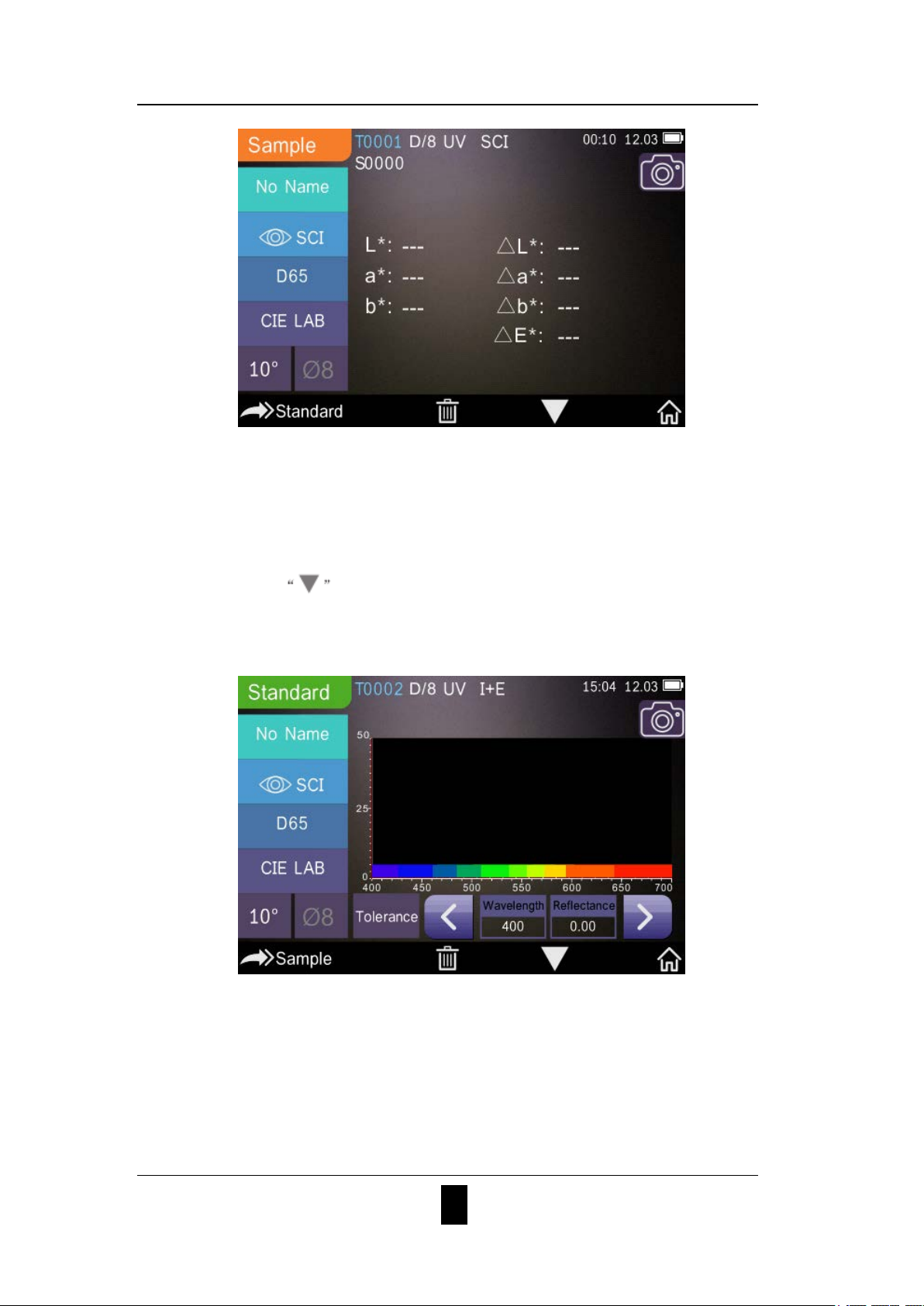
Figure 7 Sample Measurement
Figure 8 is spectral reflectance interface and Figure 9 is color index
interface. Click to do quick switchable.
Figure 8 Spectral Reflectance
8
GRATING SPECTROPHOTOMETER OPERATING MANUAL
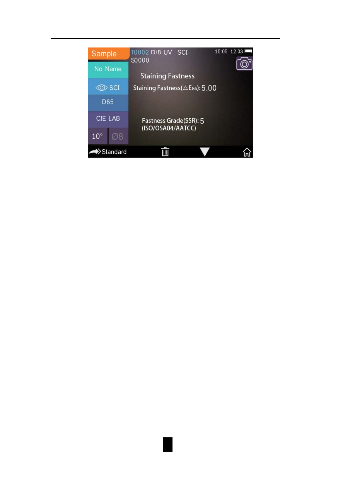
Figure 9 Color Index
2.3.2 Standard Measureme nt
Please enter “Standard Measurement” interface to perform measurements
as shown in Figure 10.
Put the measuring aperture close on the standard sample, press “Testing”
key. There is a “Beep” voice, and the LED indication light will turn to
green from yellow, then it shows measurement finished as shown in
Figure 10 and in Figure 11.
9
GRATING SPECTROPHOTOMETER OPERATING MANUAL
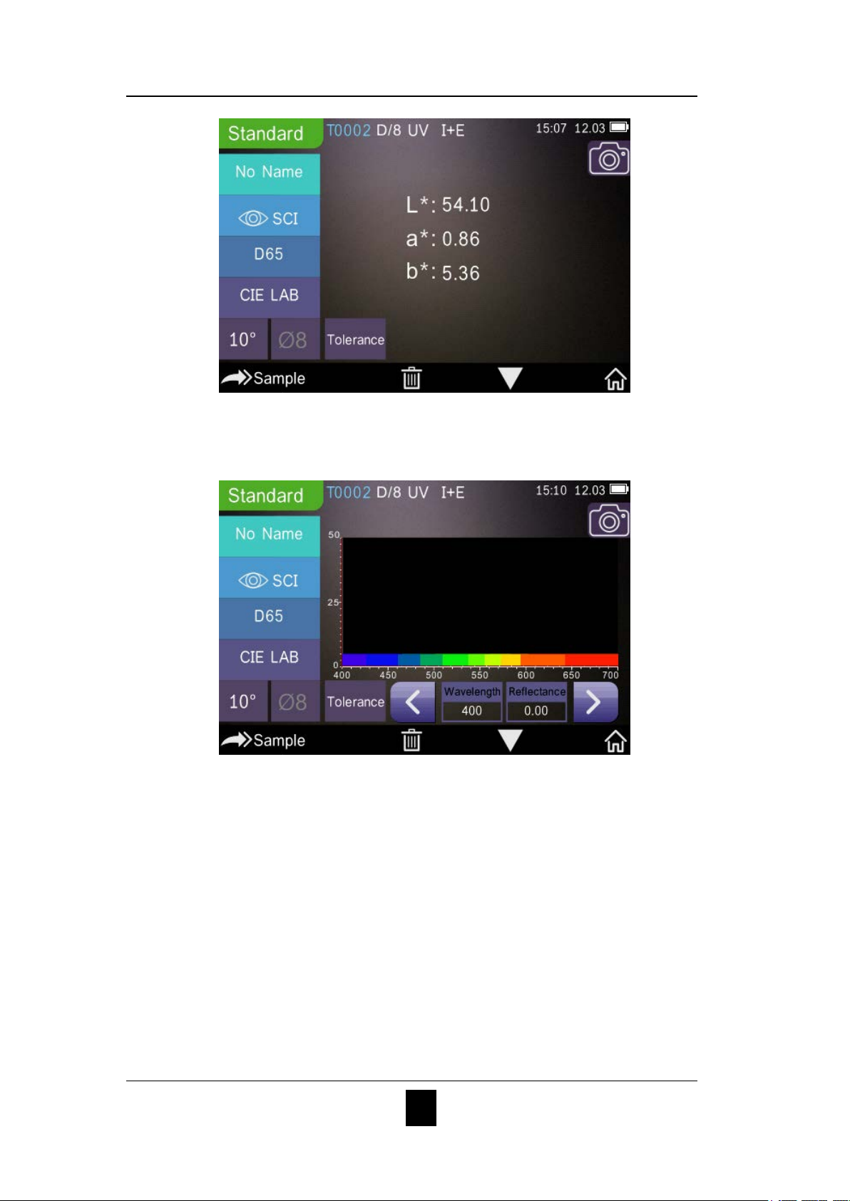
Figure 10 Standard Measurement
Figure 11 Reflectance of Standard Measurement
Detail instructions of standard measurement are as following:
1) Interface Title: Indicating it is under interface of standard
measurement.
2) Condition area: display system setting such as the current serial
number, lighting source, UV (on/off), Bluetooth (on/off), measurement
mode (I+E mode could not be used under standard measurement), and the
10
GRATING SPECTROPHOTOMETER OPERATING MANUAL
current time, date and power etc. Only when turn on Bluetooth or UV
function, they will be highlighted.
3) Camera Locating: Click to use the camera to position the measurement,
then press “Testing” button to complete measurement.
4) Serial number of standard: It is generated by the system automatically,
and started from T0001 to T1000.
5) Standard Name: Display the current measurement standard name, and
click it to quickly modify, or the default is No name.
6) Display mode: Click
to switch or click to switch
Note: The switchable of SCI or SCE model is only to display the current
data, and the sample measurement mode “SCI/SCE/I+E” is required to
switch in the system setting (Chart 3.8.5). Standard measurement model
is fixed with I+E.
7) Light Source: Click the shortcut key to switch different light among
the D 6 5、A、C、F 1 ~ F 1 2 etc.
8) Color space: Click the shortcut key to switch different color spaces
among CIE lab、CIE XYZ、Hunterlab etc.
9) Observer angle: Click to switch the observer angle 10 and 2.
10) Switch to sample measurement: Click
to sample
measurement.
11) Measurement aperture: Indicate the current measurement aperture on
use.
12) Tolerance setting: Click to set the tolerance of the current sample.
11

GRATING SPECTROPHOTOMETER OPERATING MANUAL
13) Delete/Save: If the auto-save function opens, click to delete the
current data. If the auto-save function closes, it will display save button,
and click to save the current data.
14) Page Turing: Click to quickly switch the current data among
data display area, spectrum display area and color index display area
(Please see the setting of color index as shown in Figure 36).
15) Wavelength switch button: As shown in Figure 11, click
or ,
the wave length and reflectance of the current sample will switch as range
of 10nm interval.
Note: If turn off the auto-save function, delete button will be save
button and click to save the current data.
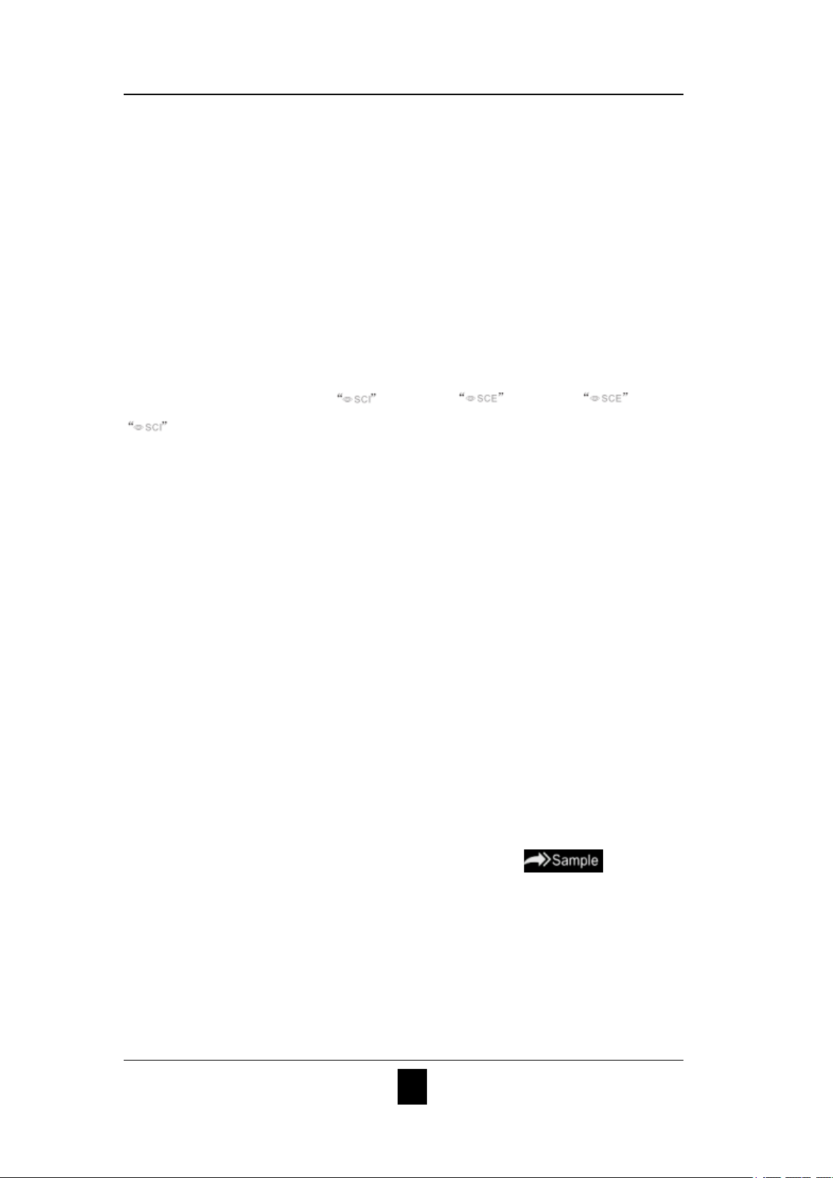
2.3.3 Sample Measurement
After testing the standard, click to enter Sample Measurement
interface. Put the measuring aperture close on the measured sample, press
“Testing” key. There is a “Beep” voice, and the LED indication light will
turn to green from yellow, then it shows measurement finished as shown
in Figure 12 and in Figure 13. Sample measurement is similar with
standard measurement but it will display the color difference between the
current standard and measured sample.
Detail instructions of sample measurement are as following:
1) Interface Title: Indicating it is under interface of sample measurement.
2) Standard Serial No: the current serial number of standard, starts with T,
12
GRATING SPECTROPHOTOMETER OPERATING MANUAL
followed by numbers, and all sample chromatic data is based on the
current standard.
3) Sample Serial No: the current serial number of sample, starts with S,
followed by numbers, generated by the system automatically, uniquely
identify current sample.
4) Standard Name: Display the current measurement standard name, and
click it to quickly modify, or the default is No name.
5) Display mode: Click
to switch or click to switch
Note: The switchable of SCI or SCE model is only to display the current
data, and the sample measurement mode “SCI/SCE/I+E” is required to
switch in the system setting (Chart 3.8.5). Standard measurement model
is fixed with I+E. If the current sample measurement mode is SCI
(Working Condition Area displays SCI), the instrument only measures
SCI data; if set the mode to SCE, there will be “-----” because no
measurement for SCE data, as well as no reflectance and color index data
under SCE mode.
6) Sample Chromatic Data: Display the current chromatic data.
7) Delta E (Color Difference): The color difference between standard and
sample.
8) Measurement Result: Display the test result under the color formula
and tolerance. If the result is larger than the tolerance value, it will show
red “Failure”, or show green “Pass”. This function only exists when you
turn on the function of “ Display Measurement Result” in the system
setting.
9) Color Offset: only display color offset when you turn on the function
13
GRATING SPECTROPHOTOMETER OPERATING MANUAL
in the system setting.
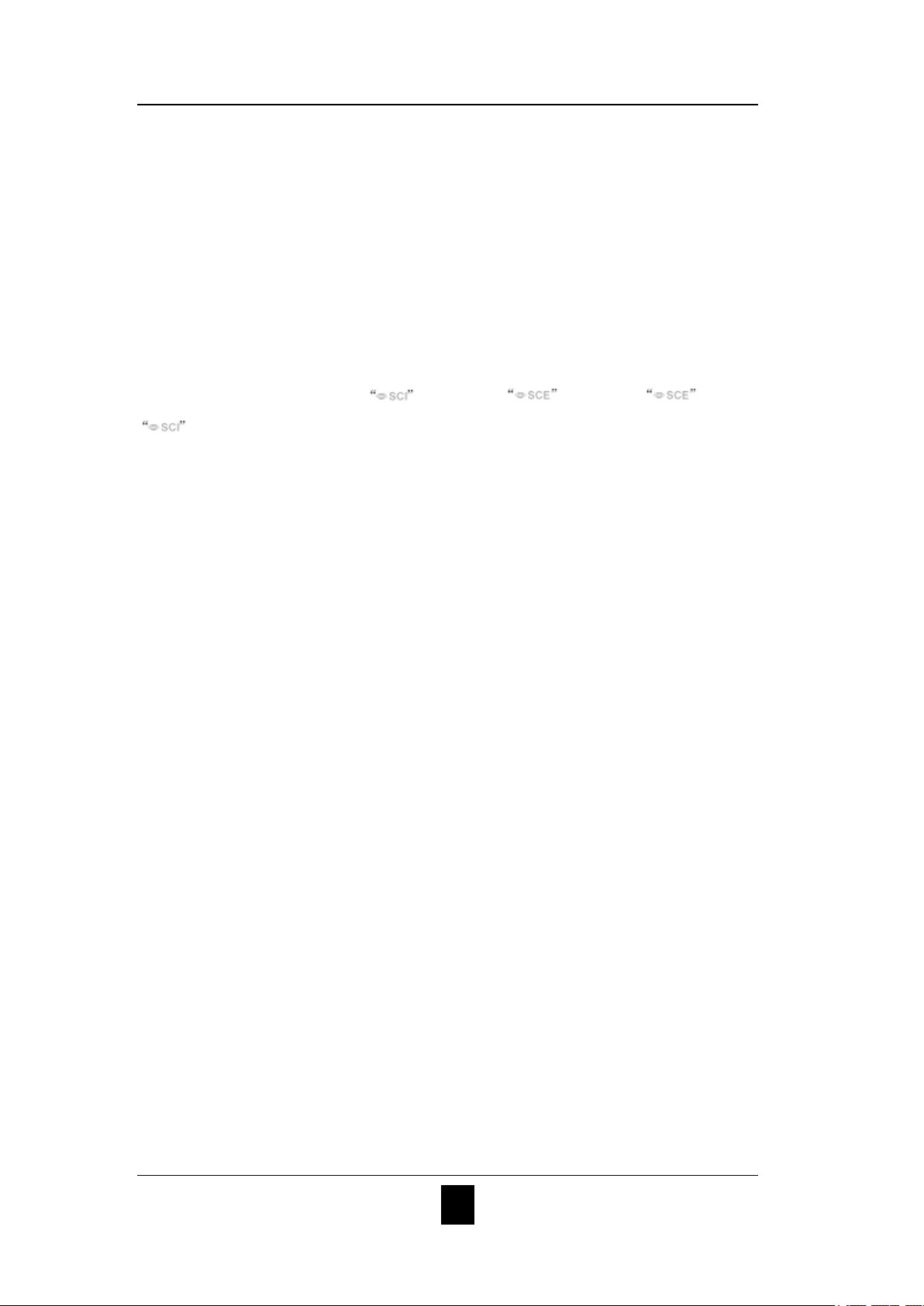
10) Wavelength switch button: As shown in Figure 13, click
or , the
wave length and reflectance of the current sample will switch as range of
10nm interval.
Figure 12 Sample Measurement
Figure 13 Reflectance of Sample Measurement
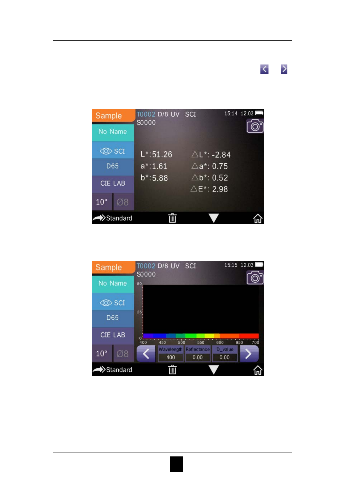
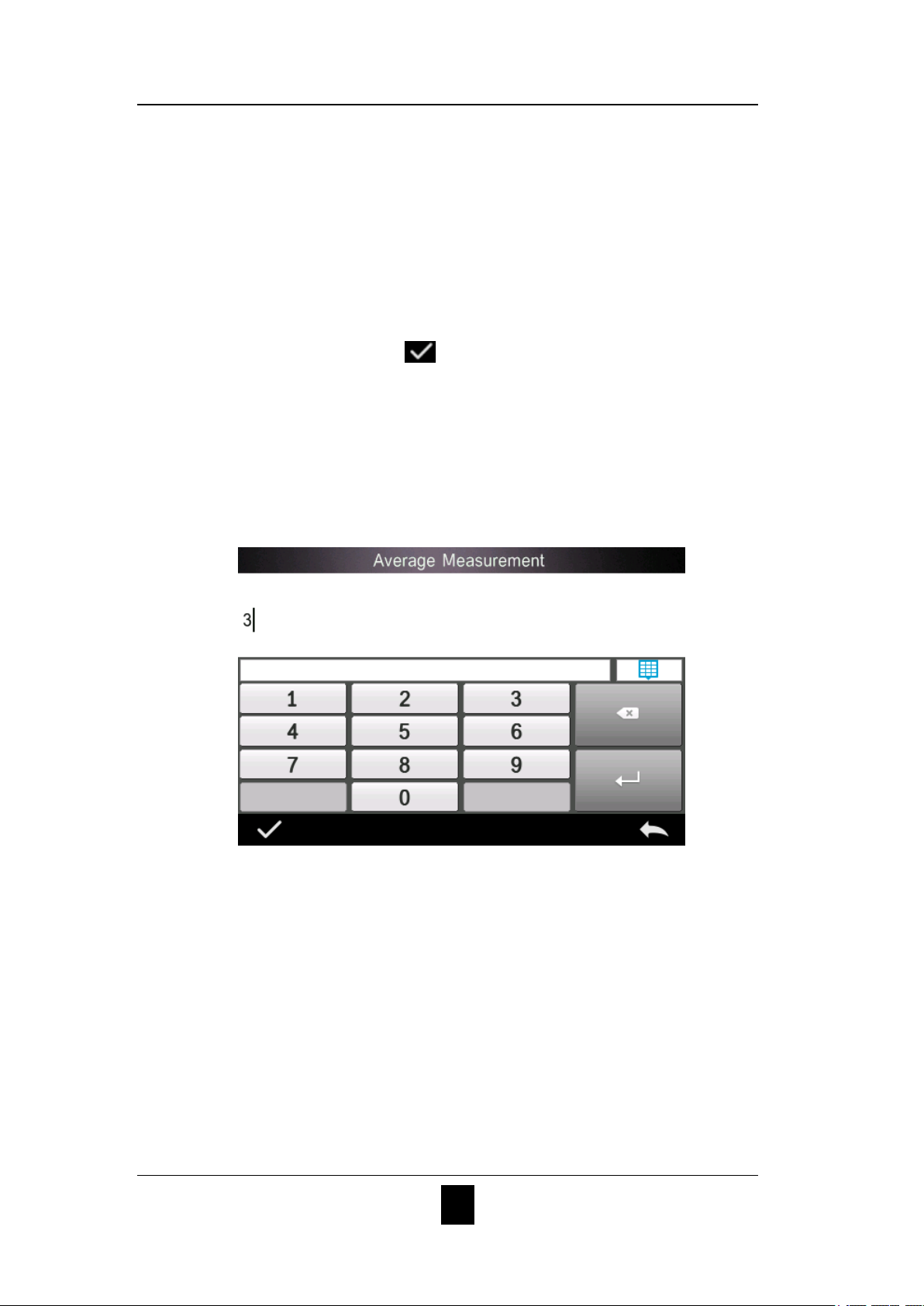
2.3.4 A verage Measurement
14
GRATING SPECTROPHOTOMETER OPERATING MANUAL
When the measured sample is very large or relatively not very uniform, it
needs to measure several points to get an average reflectance to show the
sample true chromatic value. This instrument can realize 2-99 times
average measurement.
In the main menu, click “Average Measurement” as shown in Figure 14,
input average times and click
to confirm.
If input 1 time, it measures as usual; if more than 1, it will generate
measurement results after average times under standard and sample
measurement.
Figure 14 Average Measurement
2.4 Connecting to PC
The instrument has a PC software with powerful extended function, and it
could realize more chromatic data analysis. It can connect to PC
through USB cable or Bluetooth (Only for the model with Bluetooth
function)
15
 Loading...