

PCE Health and Fitness PCE-A-315 Instruction Manual
PCE Americas Inc.
711 Commerce Way
Suite 8
Jupiter
FL-33458
USA
From outside US: +1
Tel: (561) 320-9162
Fax: (561) 320-9176
info@pce-americas.com
www.pce-instruments.com/english
www.pce-instruments.com
PCE Instruments UK Ltd.
Unit 11
Southpoint Business Park
Ensign way
Hampshire / Southampton
United Kingdom, SO31 4RF
From outside UK: +44
Tel: (0) 2380 98703 0
Fax: (0) 2380 98703 9
info@industrial-needs.com
Grain Moisture Analyzer
PCE-A-315
INSTRUCTION MANUAL

Contents
2/29
Contents
GENERAL SAFETY RECOMMENDATIONS .............................................................. 3
1. GENERAL INFORMATION ..................................................................................... 4
2. SPECIFICATIONS................................................................................................... 6
3. PRINCIPLE OF OPERATION ................................................................................. 7
4. WORKING WITH CONTROL PANEL...................................................................... 8
4.1. CONNECTIONS .................................................................................................... 8
4.2. SELECTING PRODUCT AND PERFORMING MOISTURE MEASUREMENTS ..................... 10
4.3. TREND VIEW ..................................................................................................... 13
4.4. ENTERING CORRECTIONS AND PARAMETERS ....................................................... 15
4.5. VIEWING ARCHIVE DATA ..................................................................................... 23
4.6. SETTING TIME AND DATE .................................................................................... 24
5. INSTALLATION ..................................................................................................... 25
6. TROUBLESHOOTING .......................................................................................... 27
7. DIMENSIONAL DRAWING ................................................................................... 29

General safety recommendations
3/29
General safety recommendations
The product is designed for industrial use. Installation and service must
be carried only out by trained and authorized personnel and according
to valid standards.
Before making any electrical connections, ensure that power supply
voltage and frequency meet the specifications provided on the labels of
devices and in this manual.
Incorrect connection may cause damage to the device. When installing,
always refer to relevant safety regulations.
Before carrying out any welding work near the device, make sure that
the device is disconnected from the power supply.
Do not use the device with damaged insulation of cables. In the case of
damage to the cable, disconnect the device from the power supply and
contact manufacturer or local dealer for cable replacement.
In case of device malfunction do not attempt to disassemble and repair
the device. Please, contact manufacturer or local dealer for repair.
Take precautions when mounting the equipment by using appropriate lift
gear, platforms and tools.
General information
4/29
1. General information
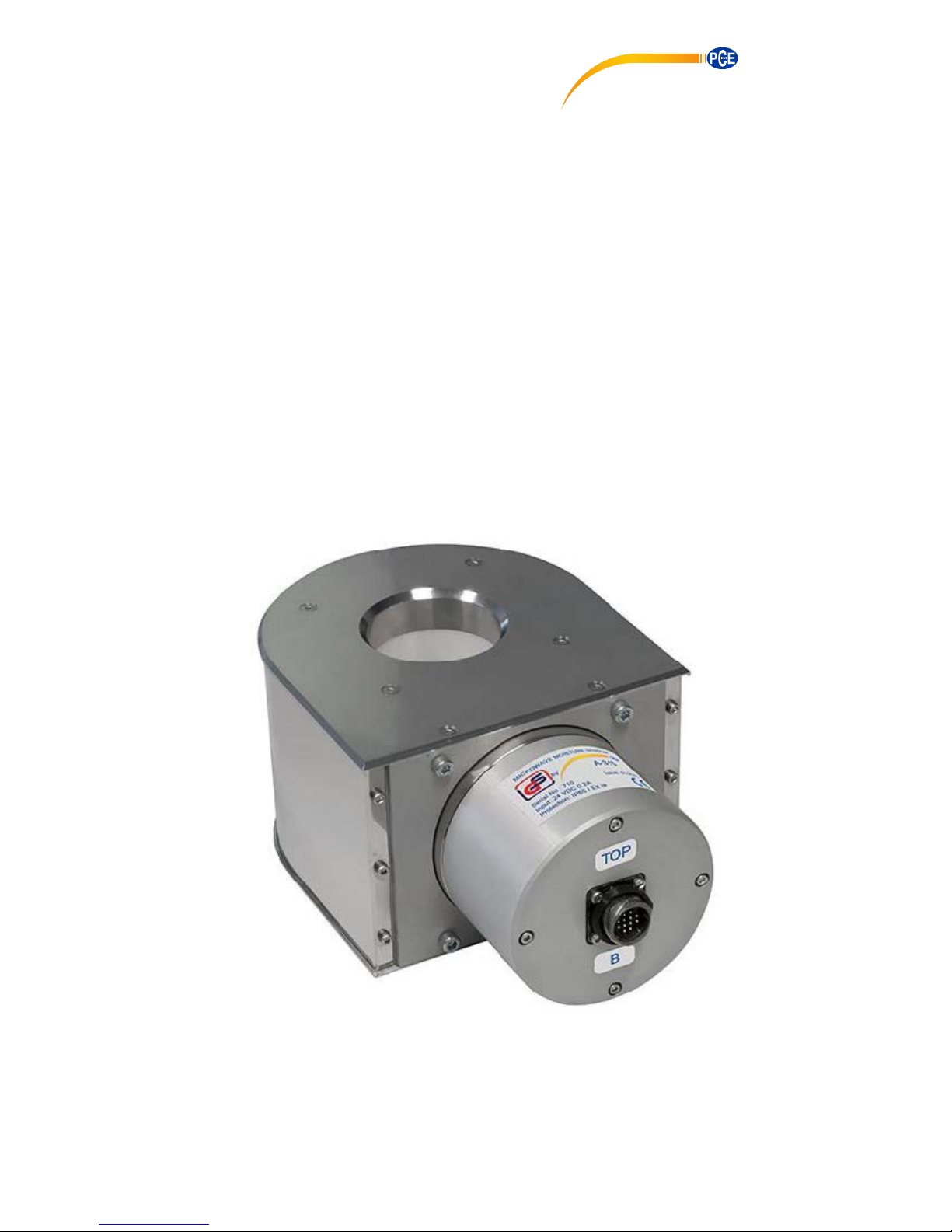
The system of online moisture content measurement is designed for continuous
measurement of current moisture content of grain products, oil or leguminous crops
and other products at inlet and outlet of continuous flow grain dryers.
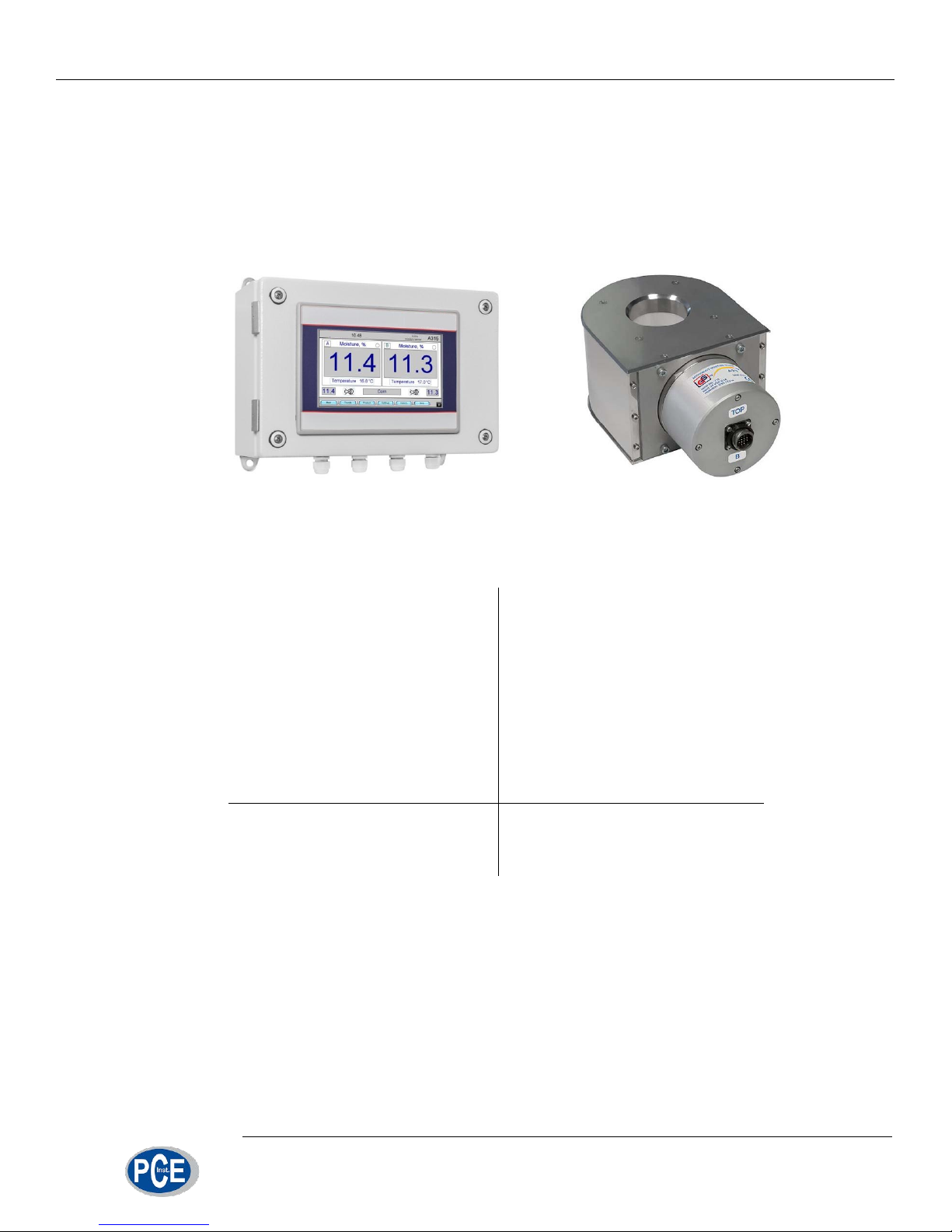
fig 1. System of online moisture content measurement
The system can be used for measuring moisture content of the following products:
Grain:
- wheat
- barley
- oats
- triticale
- rye
- corn
- buckwheat
- millet
- sorghum
- rice
Oil crops:
- rape
- sunflower
- jojoba
Leguminous
crops:
- peas
- lupine
- soybean
Other:
- seaweed
- coffee
The system of online moisture content measurement consists of two А315 microwave moisture sensors and control panel (fig. 1). One moisture sensor is installed
at the inlet of dryer and another is at the outlet of dryer. If grain drying complex has
two drying shafts, one moisture sensors can be installed at the outlet of each shaft.
Control panel is installed at the operator station and intended for monitoring of
input and output flow moisture. Information about grain moisture and temperature is
displayed in digital form and in the form of charts (trends).

General information
5/29
Control panel allows adjusting scaling settings of two moisture content current
loop outputs for use in automation systems, storing correction coefficients for measured moisture content of every product, time-averaging of measurement results and
other functions described in this manual.

Specifications
6/29
2. Specifications
Sensor type .................................................................. microwave;
Measuring mode ........................................................... continuous;
Measuring range .......................................................... 5 – 40%;
Moisture content measurement error (up to 18%) ........ ±0.5% max;
Moisture content measurement error (18-40%) ........... ±1% max;
Product temperature ..................................................... +5ºС – +55ºС;
Ambient temperature ................................................... 0ºС – +55ºС;
IP rating ....................................................................... IP65;
Communication protocol ............................................... RS-485;
Cable length between sensor and control panel .......... up to 100 m;
Analog output ............................................................... 4-20 or 0-24 mA;
Analog output loading capability .................................. 400 Ω max;
Sensor weight ............................................................... 6.5 kg;
Control panel weight ..................................................... 4.5 kg;
Control panel power supply .......................................... 100-240VAC / 50-60Hz;
Sensor power supply .................................................... 24VDC.
Principle of operation
7/29
3. Principle of operation
The principle of sensor A315 operation is based on the considerable difference
of the permittivity of dry substances and water at ultra-high frequencies (UHF).
The feature and important advantage of A315 moisture content sensor is that
due to simultaneous measurement of resonant frequency and amplitude of the resonance and special processing algorithm, moisture content measurements become
practically independent of product bulk density.
The sensing element is based on a ring resonator. The resonator has a cavity
formed by a PTFE tube for grain flow. Interaction of grain flow with resonator field inside the tube influences parameters of the resonator. Temperature sensors in measuring channel allow automatic correction of measured value of moisture content from
the grain temperature.
Electronics of the sensor consists of two units – UHF module and data processing module that control frequency response of measurement resonator, provide
necessary calculations and transfer of data to control panel via RS-485 interface.
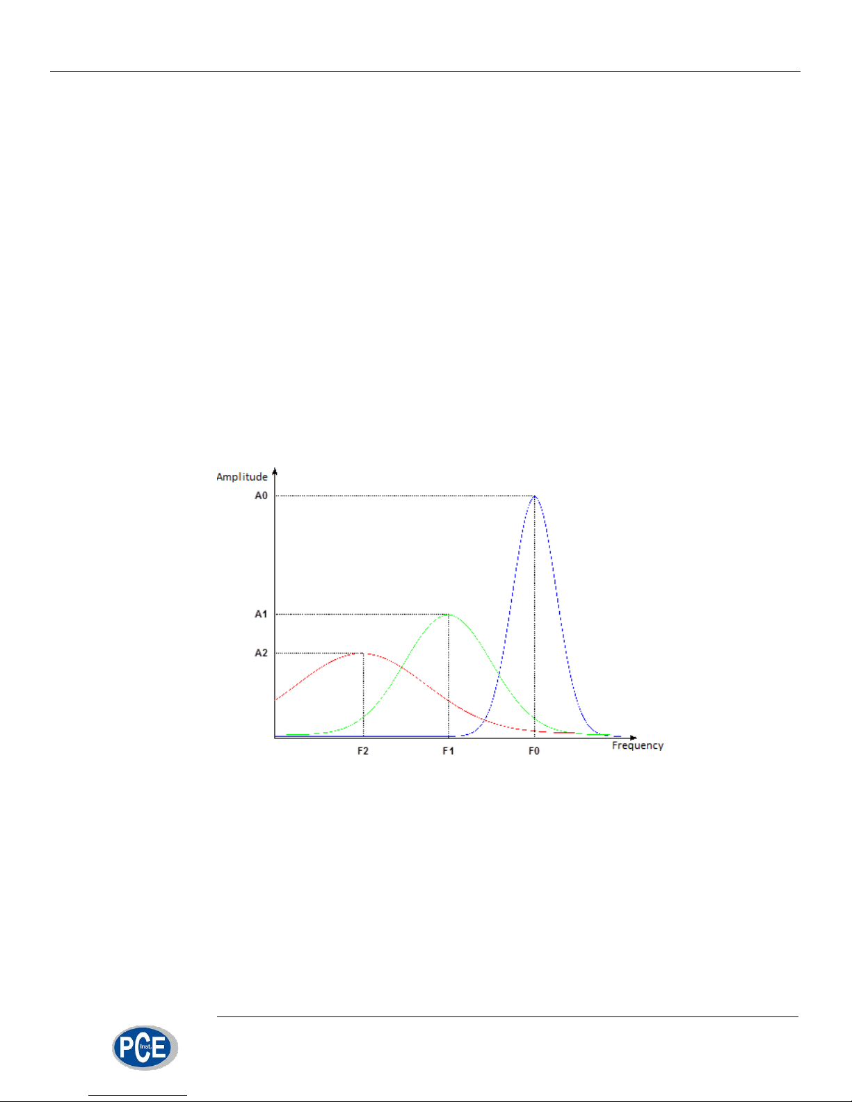
fig 2. Principle of operation
When the measuring channel is empty, the resonator has resonant frequency
F0 and amplitude A
0
(fig. 2). When the channel is filled with grain with certain mois-
ture content, the resonant frequency and amplitude decrease to F
1
and А1 respective-
ly. With the increase of moisture content in measured product, resonant frequency
and amplitude decrease even more (F
2
and А2). Simultaneous measurement of resonant frequency and amplitude allows determining moisture content independently of
grain density.
Working with control panel
8/29
4. Working with control panel
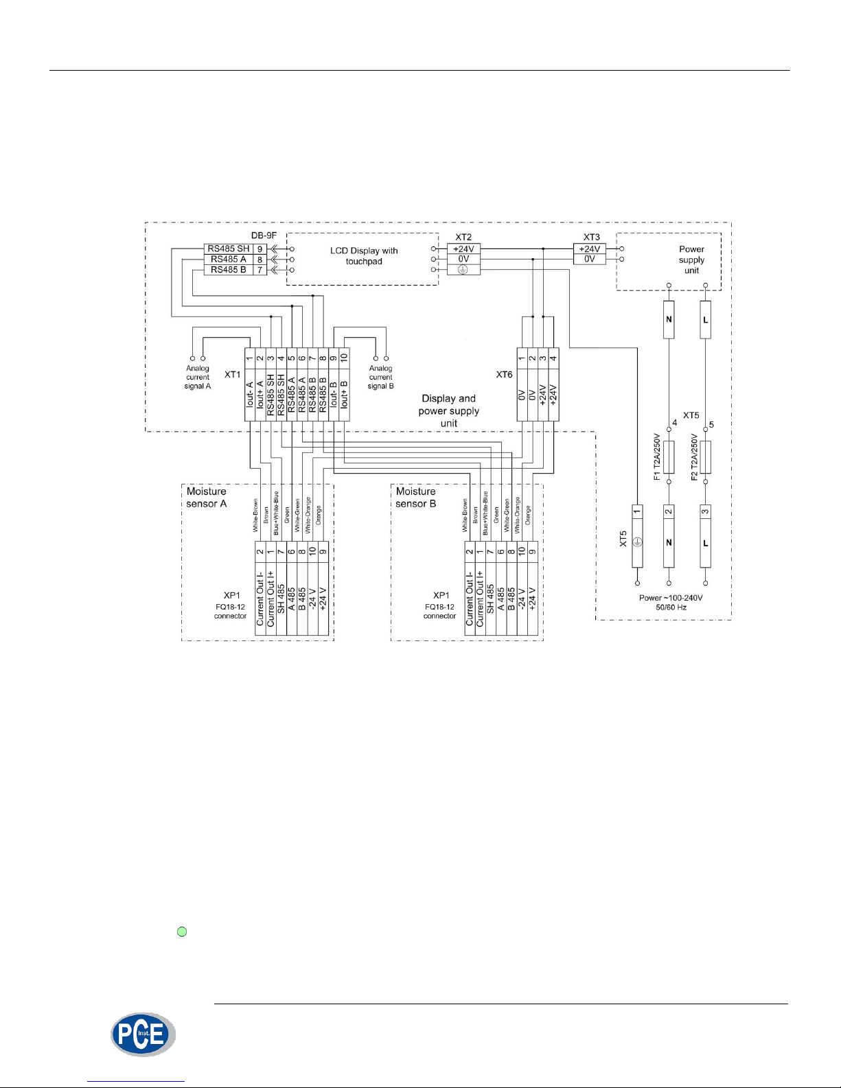
4.1. Connections
Control unit is designed to work with two A315 grain moisture content sensors.
One of the sensors has address A, and the second one – address B.
fig 3. Wiring diagram
Control panel is supplied with two pre-wired cables (3 m each) for connecting
the sensors. This allows to quickly plug the sensors and check their operation before
installation on the grain dryer and to learn how to work with the control panel.
For installation on the grain dryer 7-terminal junction box should be mounted at
the distance of up to 3 m from a sensor and sensor cable should be connected to it.
Communication lines (4 twisted pairs) of the required length (up to 100 m) from each
junction box are wired to the operator station where control panel is installed. Connections should be performed according to wiring diagram shown in fig. 3.
In order to check operation of measurement system place both sensors on a ta-
ble, connect the cables from control panel to sensors A and B and power up the con-
trol panel. After startup the display should look as shown in fig. 4. Two green indicators show that sensors are ready for measurements.
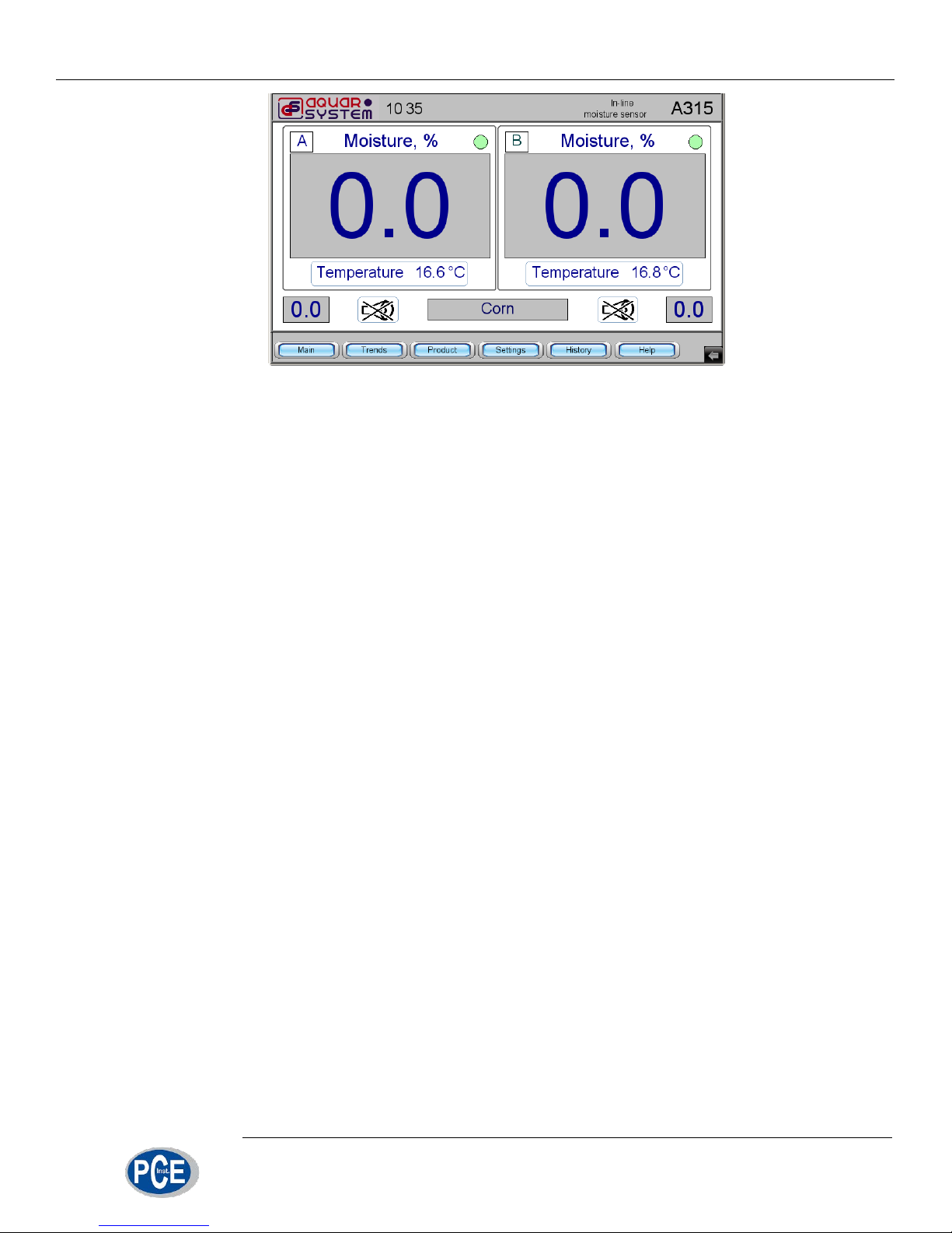
Working with control panel
9/29
fig 4. Control panel screen after system startup
 Loading...