

PCE Health and Fitness PCE-2500 User Manual
Manual
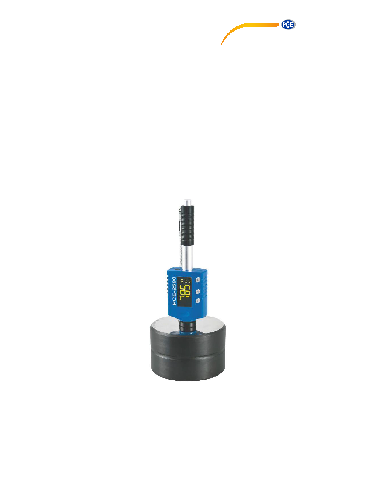
Durometer PCE-25
00
Version 1.2
26.02.2016
PCE Americas Inc.
711 Commerce Way
Suite 8
Jupiter
FL-33458
USA
From outside US: +1
Tel: (561) 320-9162
Fax: (561) 320-9176
info@pce-americas.com
www.pce-instruments.com/english
www.pce-instruments.com
PCE Instruments UK Ltd.
Units 12/13
Southpoint Business Park
Ensign way
Hampshire / Southampton
United Kingdom, SO31 4RF
From outside UK: +44
Tel: (0) 2380 98703 0
Fax: (0) 2380 98703 9
info@pce-instruments.com

Manual
2
Content
1 Introduction ............................................................................................................. 4
1.1 Forewords ................................................................................................................................... 4
1.1.1 History ............................................................................................................................................ 4
1.1.2 Leeb Hardness Test (definition) ..................................................................................................... 4
1.1.3 Notation of Leeb’s Hardness .......................................................................................................... 5
2 Safety information ................................................................................................... 5
3 Features and Application ....................................................................................... 6
3.1 Introduction ................................................................................................................................. 6
3.2 Specifications ............................................................................................................................. 6
3.3 Applications ................................................................................................................................ 6
4 Device description .................................................................................................. 7
5 Symbols and Illustrations ....................................................................................... 7
5.1 Symbols and Illustraions ............................................................................................................. 7
5.2 Measurement and Conversion Table ......................................................................................... 7
6 Preparation before Measuring ............................................................................... 8
6.1 Requirements for the sample ..................................................................................................... 8
6.1.1 The surface temperature of the sample should be less than 120 °C. ............................................ 8
6.1.2 The sample must feature a metallic smooth, ground surface, in order to eliminate erroneous
measurements brought about by coarse grinding or lathe scoring. The roughness of the finished surface
should not exceed 2 µm. .............................................................................................................................. 8
6.2 Requirements for the weight of the sample ................................................................................ 8
6.3 Requirement for the surface hardened layer of the sample ....................................................... 8
6.4 Supporting the Samples during testing ...................................................................................... 9
6.5 Samples with Curved Surfaces .................................................................................................. 9
7 Operation ............................................................................................................... 10
7.1 Button description ..................................................................................................................... 10
7.2 Diagram of operation ................................................................................................................ 11
7.3 Power on the instrument ........................................................................................................... 12
7.4 Power off the instrument ........................................................................................................... 12
7.5 Display Modes .......................................................................................................................... 13
7.6 Settings ..................................................................................................................................... 13
7.6.1 Impact Device .............................................................................................................................. 14
7.6.2 Material selection ......................................................................................................................... 14
7.6.3 Hardness scale conversion .......................................................................................................... 14
7.7 No. of test ................................................................................................................................. 14
7.8 Language selection .................................................................................................................. 14
7.9 Mean Time Setup ..................................................................................................................... 14
7.10 Upper / Lower Limit .................................................................................................................. 14
7.11 Memory ..................................................................................................................................... 15
7.11.1 MODE1 (Save single) .................................................................................................................. 15
7.11.2 MODE2 (Save Mean) ................................................................................................................... 15
7.11.3 MODE3 (Manual Save) ................................................................................................................ 15
7.11.4 View ............................................................................................................................................. 15
7.11.5 Erase ............................................................................................................................................ 15
7.11.6 File................................................................................................................................................ 15

Manual
3
7.12 Calibration................................................................................................................................. 16
7.12.1 Calibration mode .......................................................................................................................... 16
7.12.2 Adjust ........................................................................................................................................... 16
7.12.3 Calibration on ............................................................................................................................... 17
7.12.4 Calibration off ............................................................................................................................... 17
7.12.5 Calibration for DL probe ............................................................................................................... 17
7.13 Prompt Sound ........................................................................................................................... 17
8 Changing impact body .......................................................................................... 18
9 Take a measurement ............................................................................................. 18
9.1 Loading spring .......................................................................................................................... 18
9.1.1 Hold the main body (the tester) with left hand while right hand is holding the loading tube. ....... 18
9.1.2 Push the loading tube with a little force against spring force toward tester until to lock the impact
body. 18
9.1.3 Loose the force and let the loading tube return to the original position. ...................................... 18
9.2 Take measurement ................................................................................................................... 19
9.3 Release the testing force .......................................................................................................... 19
10 Maintenance and repair ........................................................................................ 19
10.1 Maintenance of the impact device ............................................................................................ 19
10.2 Charging battery ....................................................................................................................... 19
11 Disposal ................................................................................................................. 20
12 Contact ................................................................................................................... 20
Manual
4
1 Introduction
Thank you for purchasing a PCE-2500 hardness tester from PCE Instruments.
1.1 Forewords
1.1.1 History
The Leeb measuring method was first brought into measurement technology in 1978. It is
defined as the quotient of an impact body’s rebound velocity over its impact velocity,
multiplied by 1000. Harder materials produce a higher rebound velocity than softer
materials. For a specific group of material (e.g. steel, aluminum. etc.), Leeb hardness value
represents a direct relationship to its hardness properties. For ordinary metal, conversion
curves of hardness HL versus other standard static hardness (HB, HV, HRC, etc.) are
available, enabling you to convert HL into other hardness values.
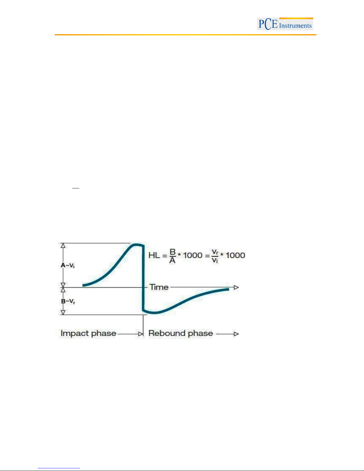
1.1.2 Leeb Hardness Test (definition)
An impact body with a spherical test tip made of tungsten carbide is propelled against the sample surface
by a spring force and then rebounds back. At a distance of 1mm from the sample surface, the impact and
rebound velocity of the impact body are measured by the following method: A permanent magnet
embedded in the impact body, when passing through the coil in its coil holder, induces in the coil an
electric voltage proportional to the velocities of the magnet. Leeb hardness is expressed by the following
formula:
1000*
Vi
Vr
HL
Where: HL is Leeb Hardness
Vr is the rebound velocity of the impact body
Vi is the impact velocity of the impact body
The voltage characteristic of output signal, when the
impact body passes through the induction coil is illustrated in the following figure:
Voltage characteristic of output signal
A Leeb’s Hardness Tester measures the hardness of sample material in terms of Hardness Leeb (HL),
which can be converted into other Hardness units (Rockwell B and C, Vicker, Brinell and Shore D).

Manual
5
1.1.3 Notation of Leeb’s Hardness
When measuring the hardness of a sample material using the traditional static hardness testing method,
a change of applied pressure will result in a change in the hardness reading. This will also happen during
a Leeb’s Hardness test when one changes the impact device. In hardness measurement of the same test
sample with different impact devices, the Leeb’s hardness values obtained will vary.
For example: 720HLD≠720HLC
Because different converting curves are obtained from different impact devices, when converting
hardness HL into different hardness values, the notation for the converted hardness value should include
the impact device used.
For example:
Hardness HRC converted from hardness L using impact device D should be written as 35, 9 HRCLD.
Where: 35=Hardness value HL
9=Hardness value HRC
L=Leeb’s Method
D=Impact device
2 Safety information
Please, read this user's handbook carefully and completely, before you put it into service for the first time.
The device may only be used by carefully trained staff. We do not assume any liability for damage and
injuries caused by non-observance of this manual.
- This meter must only be used in the way described in this manual. If used otherwise, this can lead to
dangerous situations for the user or damage / destruction of the device.
- The device may only be used in the specified temperature / humidity range. Do not expose it to extreme
temperatures, direct sunlight, extreme air humidity or moisture.
- Never use the device when your hands are wet.
- The case should only be opened by qualified personnel of PCE Instruments.
- The instrument should never be placed with the user interface facing an object (e.g. keyboard side on a
table).
- You should not make any technical changes to the device.
- The appliance should only be cleaned with a damp cloth / use only pH-neutral cleaner, no abrasives or
solvents.
- The device must only be used with original PCE spare parts or equivalent.
- Do not use the meter in explosive atmospheres.
- When the battery is flat (battery level indicator), please do not use the device anymore as false readings
can cause life-threatening situations. You can carry on with your measurement after inserting new
batteries.
- Before each use, check the device by measuring a known factor.
- The limit values for the measuring variables stated in the specifications must under no circumstances be
exceeded.
- When not using the device for a longer period of time, please remove the batteries to avoid damage due
to battery leakage.
This user's handbook is published from PCE Instruments without any guarantee.
We expressly point to our general guarantee terms which can be found in our general terms of business.
If you have any questions please contact PCE Instruments.
Manual
6
3 Features and Application
3.1 Introduction
This instrument is an advanced state-of-the-art palm sized metal hardness tester with many new features
which are light weight, easy operation, integrated design, high contrast display, low operating
temperature, auto compensating for impact direction and etc. It can be widely used for measuring
hardness of almost all ferrous and non-ferrous metal materials for scale of Leeb hardness, Rockwell C, B
&A, Brinell, Vickers, Shore and Strength.
It has a memory which can be downloaded to computer via USB port or wirelessly. All stored data can be
recalled and read on the tester easily.
The 3.7V Li-ion rechargeable battery inside the tester can be charged via USB from PC or via individual
USB charger from mains wall power. With data software for PC, customers can download measuring
values from the tester to PC and make process such as save, delete, create testing report and export
them to Excel.
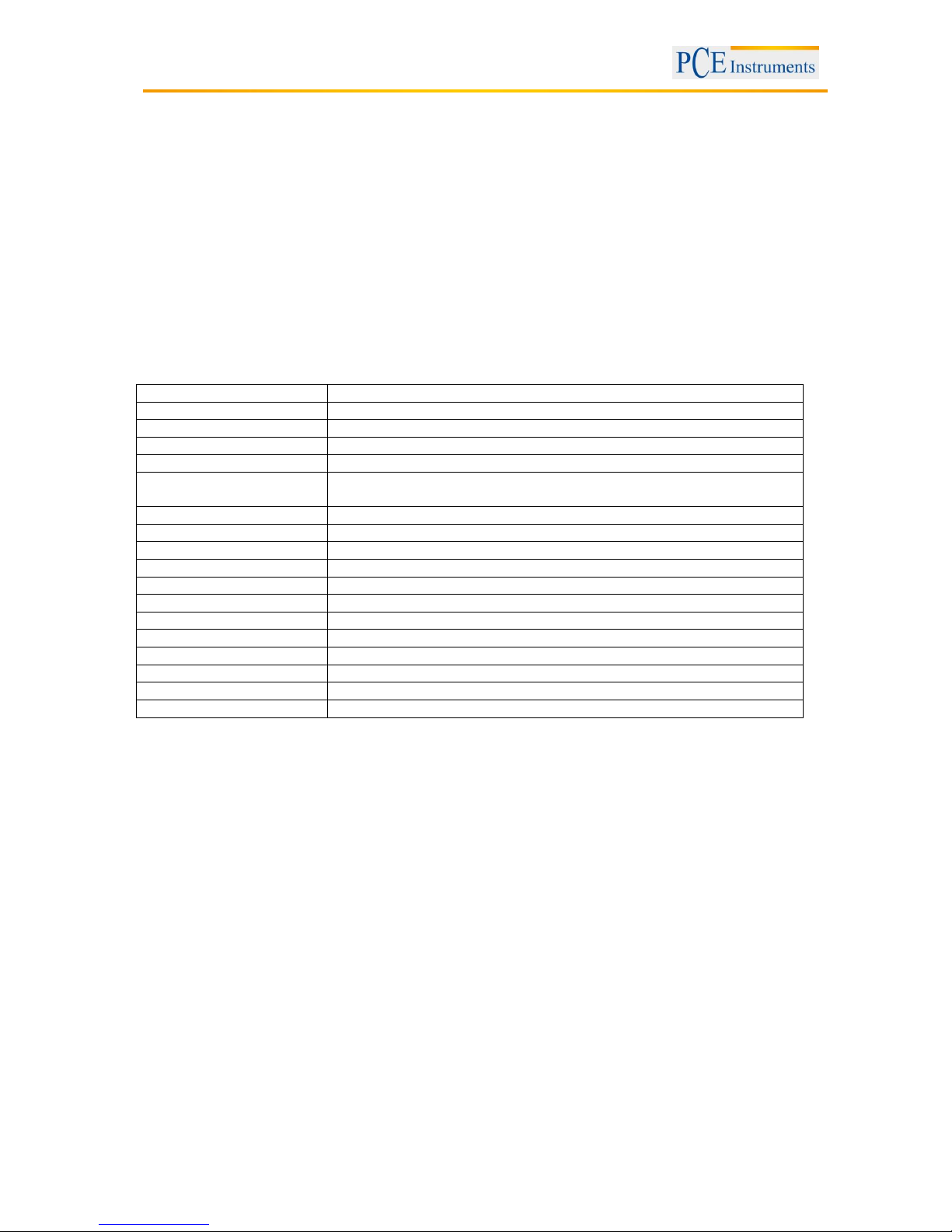
3.2 Specifications
Accuracy
+/-2HL (or 0.3%@HL=800)
Display
Digital with high contrast OLED
Impact direction
Universal angle, no need to setup impact direction
Display mode
Normal/flip or upward/downward
Hardness scale
HL / HRC / HRB / HB / HV / HS / HRA / σb
Measuring range
HL170-960 / HRC17-70 / HRB13-109 / HB20-665 / HV80-940 / HS32-
99.5 / HRA30-88 / σb(rm)255-2639N/mm2
Impact device
D
Materials
10 common metal materials
Memory
30 files, 100 data (measurement value, material, …) for each file
Interface
USB for charging
Alarm
Up or down limit
Indicator
Low battery
Power supply
3.7 V Li-ion rechargeable battery
Power on/off
Auto
Operating environment
-40 … +70 ⁰C
Dimensions (L x W x D)
148 mm × 44 mm × 22 mm
Net weight
110 g
Standards
Conforming to ASTM A956, DIN 50156, GB/T 17394-1998
3.3 Applications
- Hardness tests on installed machines or steel structures: e.g. on heavy and large work-piece or on
permanently installed system parts.
- Rapid testing of multiple measuring areas for examination of hardness variations over larger regions.
Measuring hardness for produced parts at production line.
- Identifying metallic material stored in a warehouse.
- Ineffectiveness analysis of permanent parts, pressure -vessel, turbo generator.
 Loading...