

PCE Health and Fitness N24, N25 User Manual
1
DIGITAL PANEL METER
N24 AND N25
METER SERIES
USER’S MANUAL

2

3
Contents
1. APPLICATION .............................................................................5
2. METER SET .................................................................................
5
3.
OPERATIONAL SAFETY ............................................................6
4.
INSTALLATION ............................................................................7
4.1 Fixing
Way ............................................................................7
4.2 External
Connection Diagrams ..............................................8
5.
SERVICE ...................................................................................10
5.1 Display
Description .............................................................10
5.2 Messages after Switching the Supply on ............................10
5.3 Meter
Configuration by Means of LPCon Program ............11
5.4 Manufacturer’s
Parameters of N24S, N25S ........................12
5.5 Manufacturer’s parameters of N24T, N25T ........................12
5.6 Manufacturer’s Parameters of N24Z, N25Z ........................13
5.7 Manufacturer’s
Parameters of N24H, N25H .......................14
6.
ERROR CODES ........................................................................15
7.
TECHNICAL DATA ...................................................................15
7.1 Technical
Data of N24S, N25S ...........................................15
7.2 Technical
Data of N24T, N25T ...........................................16
7.3 Technical Data of N24Z, N25Z ...........................................17
7.4 Technical
Data of N24H, N25H ...........................................17
7.5 Common Technical Data
for the Whole N24 and N25 Series .....................................18
8.
ORDER CODES ........................................................................20
9. SERVICE AND MAINTENANCE ...............................................
23

4

5
1. APPLICATION
Meters of the N24 and N25 series are digital instruments destined for the
measurement of d.c. voltage or d.c. current: uni or bipolar, temperature
through J, K thermocouples, Pt100 resistance thermometers and for the
measurement of a.c. voltage and a.c. current. A LED display (4 digits for
N24 and 5 digits for N25 meter series) constitutes the readout field.
The LPCon program is destined for the configuration of N24 and N25
meter series. One must connect the meter with the PC computer through
the PD14 programmer.
Following parameters can be reprogrammed:
- thresholds of displayed overflows,
- precision of the displayed result (decimal point),
- measurement averaging time ,
- counting of indications (individual characteristic),
- automatic or manual compensation: cold junction temperature for
measurements with thermocouples, or wire resistance for Pt100
measurements (only in N24T and N24S meters).
All meters are galvanically separated between the supply, measuring
inputs and the programmer input
Protection grade from the frontal side: IP65.
Meter overall dimensions: 96 x 48 x 64 mm (with terminals).
2. METER SET
The set is composed of:
– Meter types: N24 or N25 ........................................................... 1 pc
– User’s manual ............................................................................ 1 pc
– Guarantee card ......................................................................... 1 pc
– Clamps to fix in the panel .......................................................... 4 pcs
– Seal ............................................................................................ 1 pc
When unpacking the meter, please check whether the type and execution code on the data plate correspond to the order. If equipment is
6
incomplete or appears to be damaged, file immediately a claim with the
carrier and notify the sender at once.
3. BASIC REQUIREMENTS, OPERATIONAL
SAFETY
In the safety service scope, the meter meets the requirements of the EN
61010-1 standard.
Meaning of the symbol:
Caution: risk of hazard.
Observations concerning the operational safety
· All operations concerning transport, installation, and commissioning
as well as maintenance, must be carried out by qualified, skilled
personnel, and national regulations for the prevention of accidents
must be observed.
· The programming of N24 and N25 meter series parameters must be
carried out after disconnecting measuring circuits
· Before switching the meter on, one must check the correctness of
connections to the network.
· Do not connect the meter to the network through an autotransformer.
· Before removing the meter housing, one must switch the supply off
and disconnect measuring circuits.
· The removal of the meter housing during the guarantee contract
period may cause its cancellation.
· The meter fulfills requirements related to electromagnetic compa tibility and can be used in the industrial electromagnetic environment
· When connecting the supply, one must remember that a switch or a
circuit-breaker should be installed in the building. This switch should
be located near the device, easy accessible by the operator, and
suitably marked as an element switching the meter off.
· Non-authorized removal of the housing, inappropriate use,
incorrect installation or operation, creates the risk of injury
to personnel or meter damage.
For more detailed information, please study the User’s Manual.
7
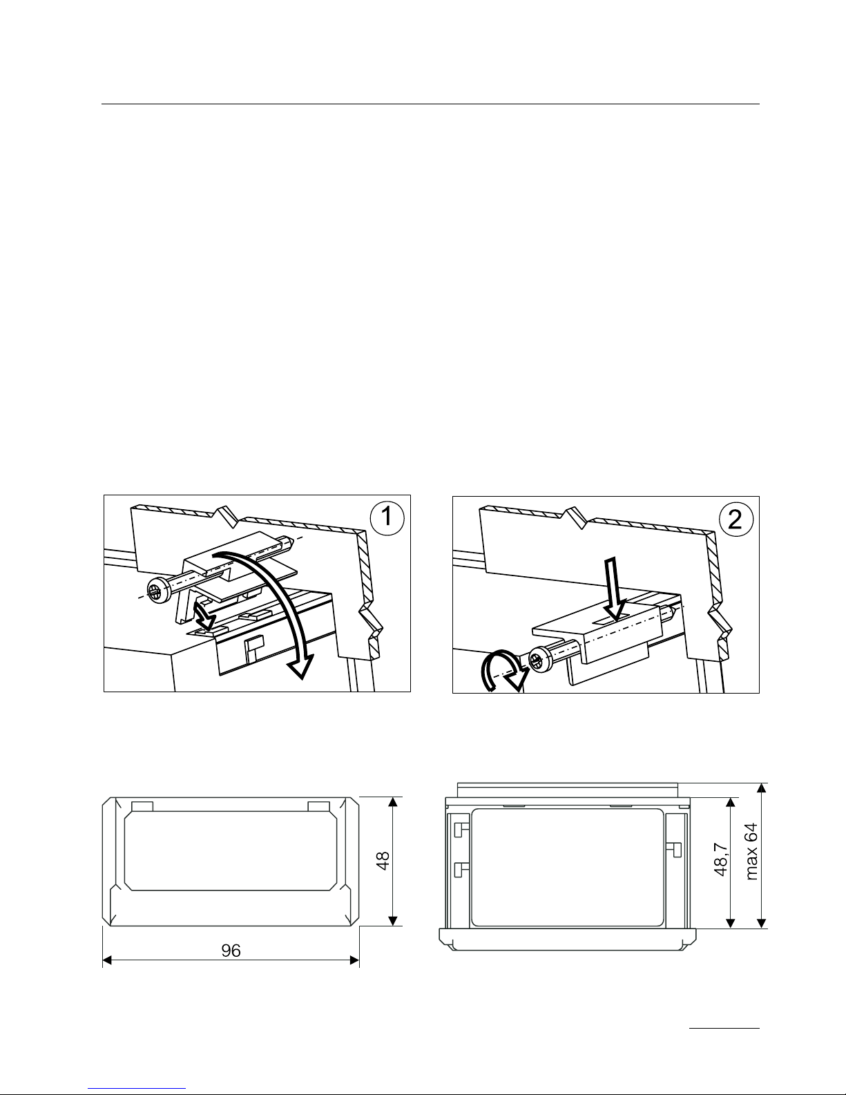
Fig. 2. Overall dimensions
Fig. 1. Meter xing
4. INSTALLATION
4.1. Fixing Way
The meter has separable strips with screw terminals which enable the
connection of external wires of 2.5 mm2 cross-section. In execution for
current measurement, the plug enables a permanent fixing to the socket by means of screws. The meter is adapted to be mounted in a
panel by means of clamps, acc. to the fig. 1.
One must prepare a hole of 92
+0,6
´ 45
+0,6
mm in the panel which the
thickness should not exceed 6 mm.
The meter must be introduced from the panel front with disconnected
supply voltage. Before the insertion into the panel, one must check the
correct placement of the seal. After the insertion into the hole, fix the
meter by means of clamps (fig.1).
8
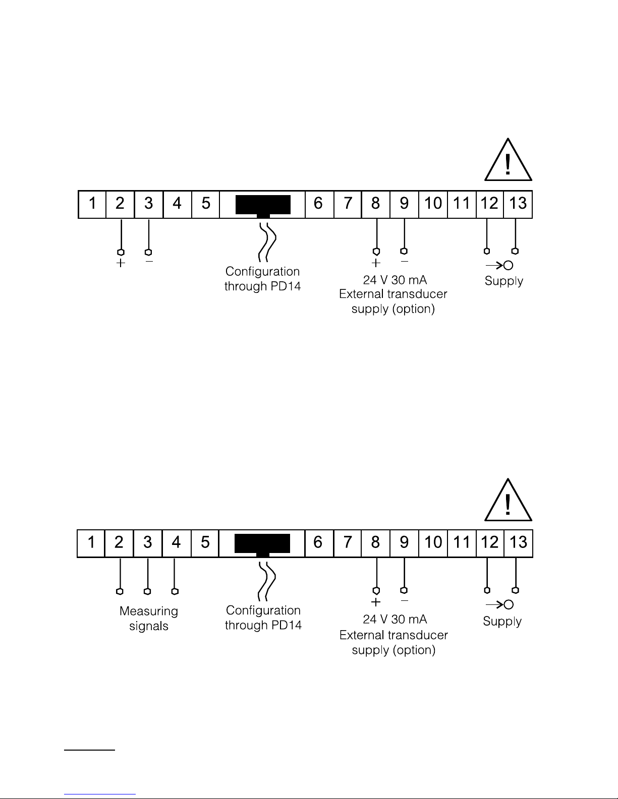
4.2. External Connection Diagrams
4.2.1 Electrical Connections of the N24S and N25S Meters
Fig. 3. Electrical connection of the N24S, N25S meters
4.2.2 Electrical Connection of the N24T and N25T Meter
Fig. 4. Electrical connection of the N24T, N25T meters
 Loading...