

PCE Health and Fitness LD120 User Manual
18/08/2005 V3.0
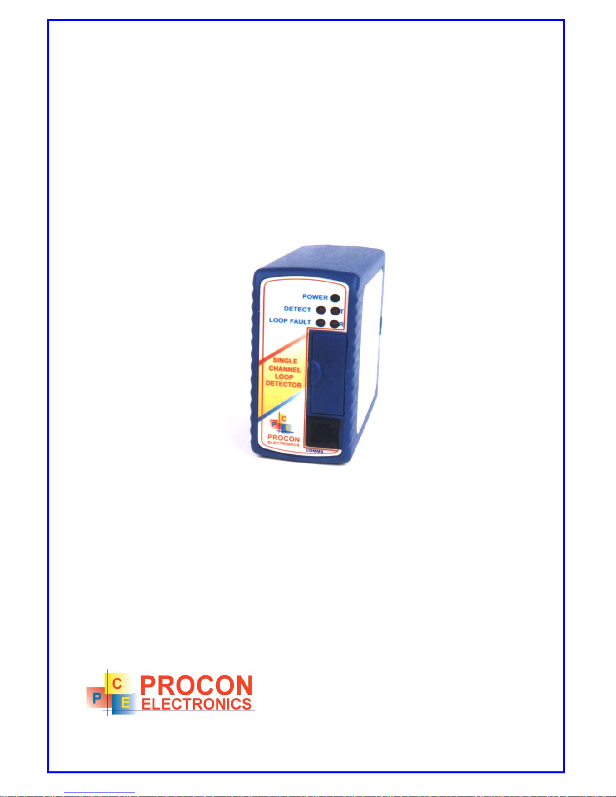
LD120
LOOP DETECTOR WITH MODBUS
COMMUNICATIONS
USER MANUAL
P.O.Box 24
STANFIELD 3613
SOUTH AFRICA
Tel: +27 (031) 7028033
Fax: +27 (031) 7028041
Email: proconel@proconel.com
Web: www.
p
roconel.com

2
TABLE OF CONTENTS
1. AN OVERVIEW OF THE LD120 MODBUS SYSTEM ............................ 3
2. LD120 HARDWARE ............................................................................... 5
2.1 SPECIFICATIONS ............................................................................... 5
2.2 WIRING................................................................................................ 6
3. DIAGNOSTICS ....................................................................................... 7
4. RELAY FUNCTIONALITY ...................................................................... 8
5. LOOP INSTALLATION GUIDE ..............................................................8
6. DATA ADDRESSES...............................................................................9
6.1 LD120 - SINGLE CHANNEL DETECTOR ( MODULE TYPE = 34).............10

3
1. AN OVERVIEW OF THE LD120 MODBUS SYSTEM
The LD120 is a series of single channel inductive loop detectors. The use of microprocessor
and surface mount technology enables a large number of functions to be incorporated into a
small package. The LD120 is compatible with most single channel detectors on the market
and is easy to set-up and install. All configuration is done through the communications port.
The LD120 is supplied with a RS485 communications port. The LD120R is supplied with a
RS232 communications port.
Typical applications in the parking and access control environments are safety loops, arming
loops and entry or exit loops.
The LD120 consists of an inductive loop detector with an integral 485 communications port.
The unit has been developed to enable remote monitoring and control of the loop detector
over a RS485 network. The communications allows access to internal setup parameters such
as sensitivity, timers, as well as counters. The LD120 can be multi-dropped on the RS485
network with other detectors and logic units, or linked to a PC running software for
configuration and monitoring of the parking system. Non volatile memory is used to store
counters and all configuration parameters.
Standard features of the logic on the unit are :
· RS485 Communications Port.
The RS485 communications port enables up to 127 detectors to be networked on a single
twisted pair cable. The LD120 communicates using the Modbus protocol in Binary mode. All
configuration data is held in modbus registers and can be setup by a PC or PLC on the
network.
· Selectable Pulse Time.
This feature sets the length of time that the pulse relay will be energized.
· Pulse Relay Selection.
The Pulse relay may be configured to energize on detection of a vehicle or when the vehicle
leaves the loop.
· Sensitivity Boost.
This feature sets the undetect level to maximum sensitivity and is used to prevent loss of
detection of high-bed vehicles.
· Switch selectable Sensitivity.
The detect sensitivity is the minimum change in inductance required to produce a detect
output. (%∆L/L) .
· Switch selectable Frequency.
The frequency of the loop is determined by the inductance of the loop and the frequency
switch setting. If the frequency switch is on, the frequency is reduced. It may be necessary to
change the frequency to prevent cross-talk between adjacent loops.
· Permanent Presence Option.

4
This feature ensures detection of the vehicle will be maintained when the vehicle is parked
over the loop for extended periods.
· Filter Option.
This option is used to provide a delay between detection of the vehicle and switching of the
output relay. This delay is normally used to prevent false detection of small or fast moving
objects.
· Loop Fault Indicator.
This LED Indicator is illuminated when the loop is either open circuit or short circuit and is
used to give a visual indication of a faulty loop.
· Power Indicator.
This LED Indicator illuminates when power is present.
· Detect Indicator.
This LED Indicator is illuminated when there is a vehicle over the loop or the loop is faulty.
This LED can also be used to determine the loop frequency. On reset, count the number of
times the LED flashes. Multiply this number by 10KHz.For example: if the LED flashes 6
times, then the loop frequency is between 60KHz and 70KHz.
• Network Layout.
The diagram below shows how the LD120 may be connected to a Modbus network. The
LD120 can be placed on the network with other I/O products such as the popular MOD-
MUX from Procon Electronics.
A typical application is where a PC (Personal Computer) is connected to the Network.
Many SCADA software packages support the MODBUS Master Protocol and can hence
retrieve data from the LD120 as well as Input Modules or send data to Output Modules.
The serial port of the PC is connected to an RS232/RS485 Converter which in turn is
connected to the Network.
SERIAL
LINK
232/485
CONVERTER
PC
8DO
OUTPUTS
120 ohm Termination
8DI
INPUTS
MODBUS MASTER
MODBUS SLAVE
LD120
I/O
 Loading...