

PCE Americas PCE-LCT 1 User Manual
AC LEAKAGE Multimeter
PCE-LCT 1
USER’ S MANUAL
PCE Americas Inc.
711 Commerce Way
Suite 8
Jupiter
FL-33458
USA
From outside US: +1
Tel: (561) 320-9162
Fax: (561) 320-9176
info@pce-americas.com
www.pce-instruments.com/english
www.pce-instruments.com
PCE Instruments UK Ltd.
Units 12/13
Southpoint Business Park
Ensign way
Hampshire / Southampton
United Kingdom, SO31 4RF
From outside UK: +44
Tel: (0) 2380 98703 0
Fax: (0) 2380 98703 9
info@pce-instruments.com

1
TABLE OF CONTENTS
Ⅰ.Features…………………………………………………………………………1
Ⅱ.Panel Description………………………………………………………………2
Ⅲ.Operation lnstructions…………………………………………………………4
A.AC Leakage current Measurements………………………………………4
1.Leakage current Flowing into Ground Conductor……………………4
2.Out of Balance Leakage current…………………………………………5
3.Using the 50/60and Wide Selector………………………………………6
B.AC Load Current Measurement……………………………………………7
C.AC Voltage Measurements…………………………………………………7
D.Resistance and continuity Measurement…………………………………8
E. Relative Reading Measurements…………………………………………8
F. Holding the LCD Reading……………………………………………………8
G.Finding the MAX/MIN Value…………………………………………………8
H.Auto-Power-Off………………………………………………………………9
IV.Specifications……………………………………………………………………9
V. Battery Replacement…………………………………………………………10
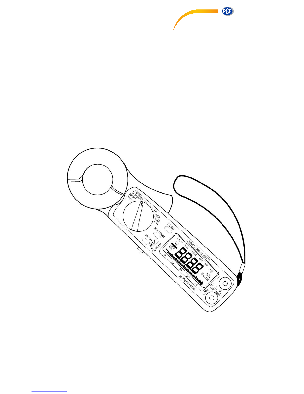
Ⅰ.Features
1.Accurate AC digital clamp meter for leakage current measurement.
2.10μA high resolution on 40mA range.
3.Shield transformer jaws to minimizs the effect of external stray
magnetic field.
4.Large jaw with 30 mm diameter.
5.Five Ranges (40mA, 400mA,4A,40A,100A)for all application.
6.A filter circuit is designed to eliminate the effect of high frequency
noise and harmonics by setting the frequency selector switch at the
50/60 Hz position for AC current measurement.
7.Large 3 3/4 digits LCD
8.Fast bargraph display (20 times/sec.)for transient observation.
9.Continuity and frequency measurements.
10.Max/Min and Data Hold functions.
11.Relative Measurement.
12.600V overload protection for ohm measurement.
13.Easy single rotary switch for any function selection.
2
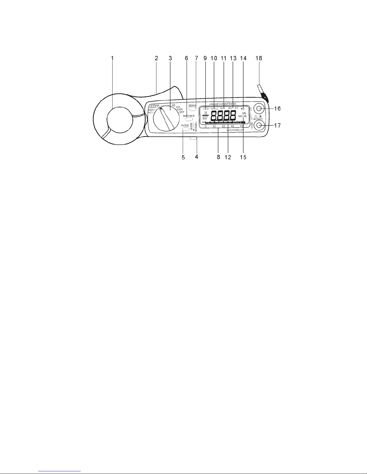
Ⅱ.Panel Description
1.Transformer Jaw
This is used to pick up current signal.To measure DC/AC current,
conductor must be enclosed by the jaw.
2.Transformer Trigger
This is used to open the jaw.
3.Function Selector Switch
This is used to select the function user desired, such as ACV ,ACA,ohm
and continuity.
4.Frequency Selection Switch
At 50/60Hz position,only the low frequency signal is measured.At wide
position,signal from 40-1KHZ is measured.
5.Data Hold Button
once this button is pushed,reading shall be held on the LCD. Press
again to release it.
6.Max/Min Hold Button
This button is used to enable the maximum or minimum value to be
displayed and updated during measurement. Press once, minimum
value shall be displayed and updated. press again, maximum value shall
be displayed and updated. Press again (the third push ),clamp meter
return to normal measurement mode.
7.Zero/Relative Button
once this button is pressed, the current reading shall be set to zero and
be used as a zero reference value for all other subsequent
measurement.

3
8.LCD
This is a 3 3/4 digit liquid crystal display with maximum indication off
3999. Function symbols, units, bargraph, sign, decimal points, low
battery symbols, Max/Min symbols, and zero symbol are included.
9.Low Battery Symbol
When this symbol appears, it means the battery voltage drops below the
minimum required voltage. Refer to Section V for battery replacement.
10.Zero/Relative Symbol
When this symbol appears, it means a reference value has been
subtracted from the actual reading. The reading shown is a offseted
value. Press and hold the zero button for 2 seconds to disable this
function.
11.Data Hold Symbol
Once the hold button is pressed, this symbol appears on LCD.
12.Bargraph
Bargraph has forty segments. It displays segments proportional to the
actual reading. Each segment represent one count.
13. Max/Min Hold symbol
Once the Max/Min button is pressed, either MAX or MIN shall be
displayed on LCD.
14.Continuity Symbol
If ohm and continuity function is selected, this symbol shall appears on
LCD.
15.Units symbols
Once a function is selected, corresponding unit (V,Ω, A,or Hz) shall be
displayed on LCD.
16.V Ω Hz input Terminal
This terminal is used as input for voltage, ohm/continuity, or frequency
measurements.
17.COM Terminal
This terminal is used as common reference input.
18.Hand strap
Put your hand through the hole of hand strap to avoid accidental drop of
the clamp meter.
 Loading...