

Page 1
1 2
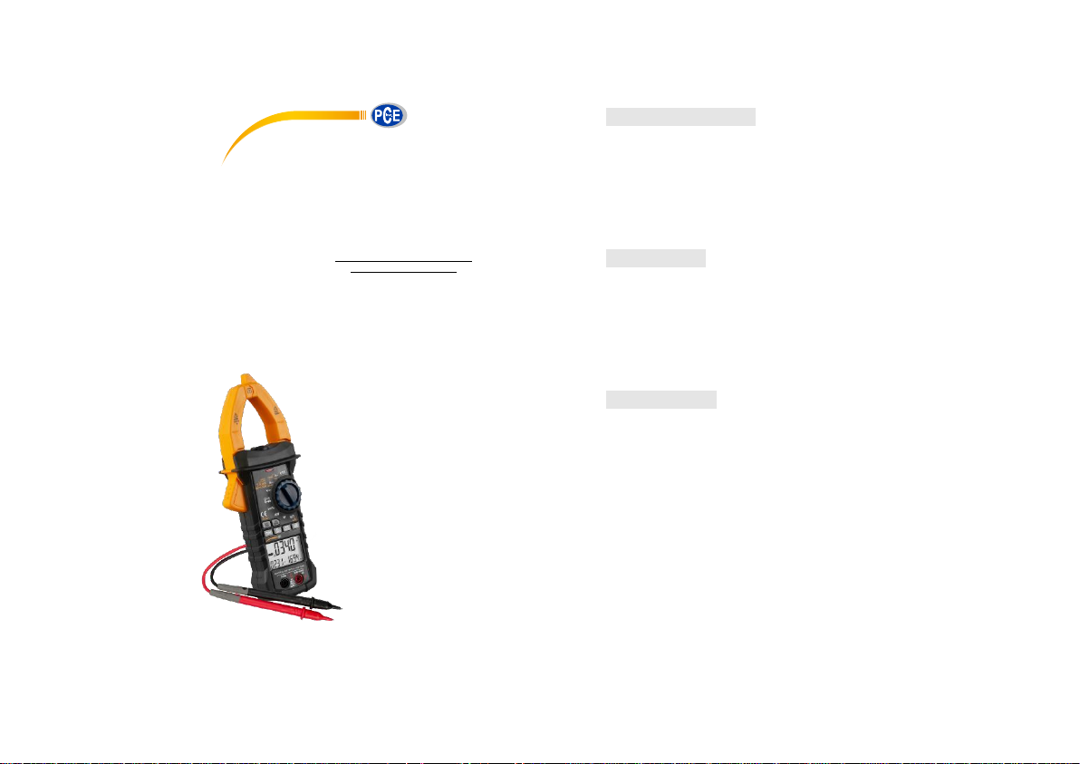
PCE-PCM 3 Digital Clamp Meter
1. Safety information ............................................. 3
1.1 Preparation ............................................. 3
1.2 Use ......................................................... 4
1.3 Mark........................................................ 5
1.4 Maintenance ........................................... 5
2. Description ........................................................ 6
2.1 Name of parts ......................................... 7
2.2 Descriptions of switch, button and input
jack ............................................................... 8
2.3 LCD display .......................................... 10
3. Specification.................................................... 11
3.1 General ................................................. 12
3.2 Technical specifications ........................ 12
3.2.1 Alternating current ..................... 13
3.2.2 Inrush current ............................ 13
3.2.3 DC voltage ................................ 13
3.2.4 AC voltage ................................. 14
3.2.5 Frequency ................................. 14
3.2.6 Duty ratio ................................... 16
PCE Americas Inc.
1201 Jupiter Park Drive
Suite 8
Jupiter
FL-33458
USA
From outside US: +1
Tel: (561) 320-9162
Fax: (561) 320-9176
info@pce-americas.com
PCE Instruments UK Ltd.
Unit 11
Southpoint Business Park
Ensign way
Hampshire / Southampton
United Kingdom, SO31 4RF
From outside UK: +44
Tel: (0) 2380 98703 0
Fax: (0) 2380 98703 9
info@pce-instruments.co.uk
www.pce-instruments.com/english
www.pce-instruments.com
Page 2

3 4
3.2.7. Resistance ................................ 16
3.2.8 Circuit continuity test ................. 17
3.2.9. Capacitance .............................. 17
3.2.10 Diode test ................................ 17
3.2.11 Single-phase active power ....... 18
3.2.12 Single-phase apparent power .. 18
3.2.13 Single-phase reactive power ... 19
3.2.14 Power factor ............................ 19
3.2.15 Harmonics measurement......... 19
4 Operation Guide ............................................... 19
4.1 Reading holding .................................... 19
4.2 Manual range ........................................ 20
4.3 Switchover of frequency and duty ratio . 20
4.4 Selection of maximum/minimum value
measurement .............................................. 21
4.5 Function switching ................................ 21
4.6 Measurement of relative value .............. 22
4.7 LINK measurement ............................... 22
4.9 ▼function .............................................. 23
4.10 ▲function ........................................... 23
4.11 INRUSH measurement ....................... 24
4.12 Back-light and clamp lighting .............. 24
4.13 Automatic shutdown............................ 25
4.14. Measurement preparation .................. 25
4.15 AC current measurement .................... 25
4.16. Voltage measurement ........................ 27
4.17 Measuring frequency and duty ratio.... 28
4.18 Resistance measurement ................... 31
4.19 Diode test ........................................... 32
4.20 Circuit continuity test........................... 33
4.21 Capacitance measurement ................. 34
4.22 Measurement of inrush current ........... 35
4.23 NCV measurement ............................. 36
4.24 Active power measurement ................ 37
4.25 Apparent power measurement ............ 39
4.26 Power factor measurement ................. 41
4.27 Phase angle measurement ................. 42
4.28 Harmonics measurement (voltage signal)
Page 3

5 6
.................................................................... 44
4.29 Harmonics measurement (current signal)
.................................................................... 46
5 Maintenance ..................................................... 47
5.1 Battery replacement .............................. 47
5.2 Probe replacement ................................ 48
6 Attachments ..................................................... 48
1. Safety information
Warning
Please pay special attention when using this
meter, improper use may result in electric
shock or damage to the meter. Please follow
the common safety rules, and fully comply
with the safety precautions specified in the
user manual.
To make full use of the meter, and ensure safe
operation, please read carefully and follow the
application methods in this specification.
This meter conforms to GB/T 13978-92: Generic
Specification for Digital Multi-meters, GB4793.11995 (IEC-61010-1, IEC-61010-2-032): Safety
Requirements of Electronic Measuring Instrument.
It causes secondary pollution, and the over-voltage
standard is CAT IV 600 V and CAT III 1,000 V.
Please abide by the safe operation guidance to
ensure the safety use of the meter. Appropriate use
and protection of the meter will bring you
satisfactory service.
1.1 Preparation
1.1.1 The users must comply with the following
safety regulations when using the meter:
- General electric shock protection
- Prevent the misuse of the meter
1.1.2 After receiving the meter, check whether it is
damaged in the transportation.
Page 4

7 8
1.1.3 Check and verify whether the meter is
damaged after being stored and shipped in poor
condition.
1.1.4 The probe must be in good condition. Check
whether the insulation of the probe is broken and
the metal wire of the conductor is exposed before
using.
1.1.5 The probe provided with the meter can ensure
the safe use, and it must be replaced with the same
probe or the probe of the same grade, if necessary.
1.2 Use
1.2.1 You must use the meter according to
requirements of correct functions and measuring
range.
1.2.2 Do not exceed the indicated value of
protection scope of each measuring range during
the measurement.
1.2.3 Do not touch the top of the probe when the
meter is connected for measuring the circuit.
1.2.4 During the measurement, if the measured
voltage is higher than 60V DC or 30 V AC (effective
value), you should keep your fingers behind the
probe protector all the time.
1.2.5 Do not measure the voltage when the AC
voltage between the measuring terminal and the
ground is greater than 750 V.
1.2.6 Select the highest range of the manual range
if you don't know the measured value in advance.
1.2.7 Remove the probe from the measured circuit
before rotating the change-over switch to change
the measuring function.
1.2.8 Do not perform the live line measurement for
the resistance, capacitance, diodes and circuit
continuity.
Page 5
9 10
1.2.9 Do not connect the meter to the voltage source
during the current, resistance, capacitance, diodes
and circuit continuity test.
1.2.10 Do not measure the capacitance before the
capacitor is fully discharged.
1.2.11 Do not use this meter near the explosive gas,
steam or dust.
1.2.12 In case of any abnormality or fault, please
stop using the meter.
1.2.13 Do not use this meter, unless the bottom
case and the battery cover are fully fastened in situ.
1.2.14 Do not store or use this meter in direct
sunlight, high temperature, or high humidity.
1.3 Mark
Note (See the operation manual for the important
safety information)
It can be used for dangerous energized
conductors.
Double insulation protection (CAT II)
CAT III complies with the over-voltage
(installation) class III of IEC-61010-1, and the
pollution level 2 refers to the level of the pulse
withstand voltage protectionprovided.
Conform to the European Union (EU) Standard
Grounding
1.4 Maintenance
1.4.1 Do not try to open the bottom case of the
meter for adjustment or repair. These operations
can only be performed by the technicians who
understand the meter and the shock hazard
adequately.
Page 6

11 12
1.4.2 Please remove the probe from the measured
circuit before opening the bottom case or the battery
cover of the meter.
1.4.3 In order to avoid the electric shock caused by
the incorrect reading, when the meter displays "
"replace the battery immediately.
1.4.4 Use wet cloth and mild detergent to clean the
meter, and do not use the abrasive or solvent.
1.4.5 Turn off the power of meter when you don't
use it, rotate the range switch to the OFF gear.
1.4.6 Take off the battery to prevent the damage to
the meter, if you do not use it for a long time.
2. Description
- PCE-PCM 3 single-phase clamp-type harmonic
power meter is hand-type intelligent power
measuring meter, which combines the digital
multimeter and power measurement with Bluetooth
function. The range switch with one-handed
performance is convenient for the measurement,
and this meter can perform the functions of overload
protection and low battery indicator.
- The meter can be used for the measurement of the
alternating current, alternating voltage, direct
voltage, frequency, duty ratio, resistance and
capacitance and circuit continuity, diode test, noncontact voltage detection, as well as the
measurement of the active power, reactive power,
apparent power, power factor, harmonics
measurement and phase angle measurement.
- The meter supports the auto range and manual
range.
Page 7

13 14
- The meter supports reading holding.
- The meter supports maximum measurement.
- The meter supports minimum measurement.
- The meter supports relative measurement.
- The meter supports Bluetooth.
- The meter supports data storage.
- The meter supports back-light and clamp lamp.
- The meter supports automatic shutdown.
- The meter supports low voltage indicator.
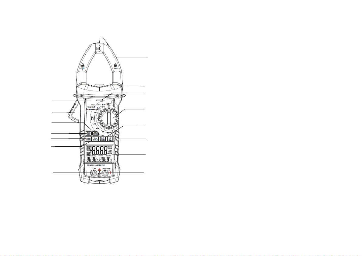
2.1 Name of parts
(1) Current clamp: for current measurement.
(2) Clamp lamp
(3) Faceplate
(4) Trigger
(5) Button for data storage and switch of auto and
manual range
(6) Button for maximum/minimum selection
(7) Button for function switch
(8) Button for reading holding/back-light
(9) Button for frequency and duty ratio
measurement, inrush current and up
(10) Button for Bluetooth function, relative
measurement and down
(11) Change-over switch
(12) NCV indicator light
(13) LCD display
(14) Input jack of resistance, capacitance, voltage,
frequency, diode and continuity.
(15) Jack of common terminal
Page 8
15 16
2.2 Descriptions of switch, button and input jack
FUNC button: for switching the measurement
function.
B.L/HOLD button: the readings will be held by the
short press, and the back-light will be turned on by
long press. The back-light and clamp lamp will be
turned on at the same time by pressing the
B.L/HOLD button in the current gear and in the
power gear on the current interface.
REC/RANGE button: short press for switching
between auto and manual range mode, and long
press for data storage.
1
2
3
4
5 6 7
8 9 10
11
12
13
14
15
Page 9

17 18
LINK/REL/▼ button
1)Long press for validating Bluetooth in all gears.
2)Short-press in the harmonic measurement
interface at KW and W gears to scroll down, and to
switch between the 1st harmonic and 20th harmonic.
At the KW and W gears, short-press the function key
in the maximum/minimum value measurement
interface to scroll down, and switch and display the
maximum/minimum value.
3)Short press on alternating current, AC/DC
voltage and capacitance for relative value
measurement mode.
Hz%/INRUSH/▲button
1) Short press on alternating current, alternating
voltage and HZ% gear for the switch among
alternating current or alternating voltage, frequency
and duty ratio.
2) Short-press on the harmonic measurement
interface at KW and W gears to scroll up, and switch
between the 1st harmonic and 20th harmonic. At the
KW and W gears, short-press the function key in the
maximum/minimum value measurement interface to
scroll up, and switch and display the
maximum/minimum value.
3) Long press on the alternating current gear for
switching to the measurement mode of inrush
current.
MAX/MIN button: for the switch between the
maximum/minimum measurement.
OFF gear: for power off.
Page 10
19 20
INPUT jack: input terminal of voltage, resistance,
frequency, duty ratio, capacitance, diode and circuit
continuity.
COM jack: common terminal of voltage, resistance,
frequency, duty ratio, capacitance, diode and circuit
continuity.
Change-over switch: for selection of functions and
ranges.
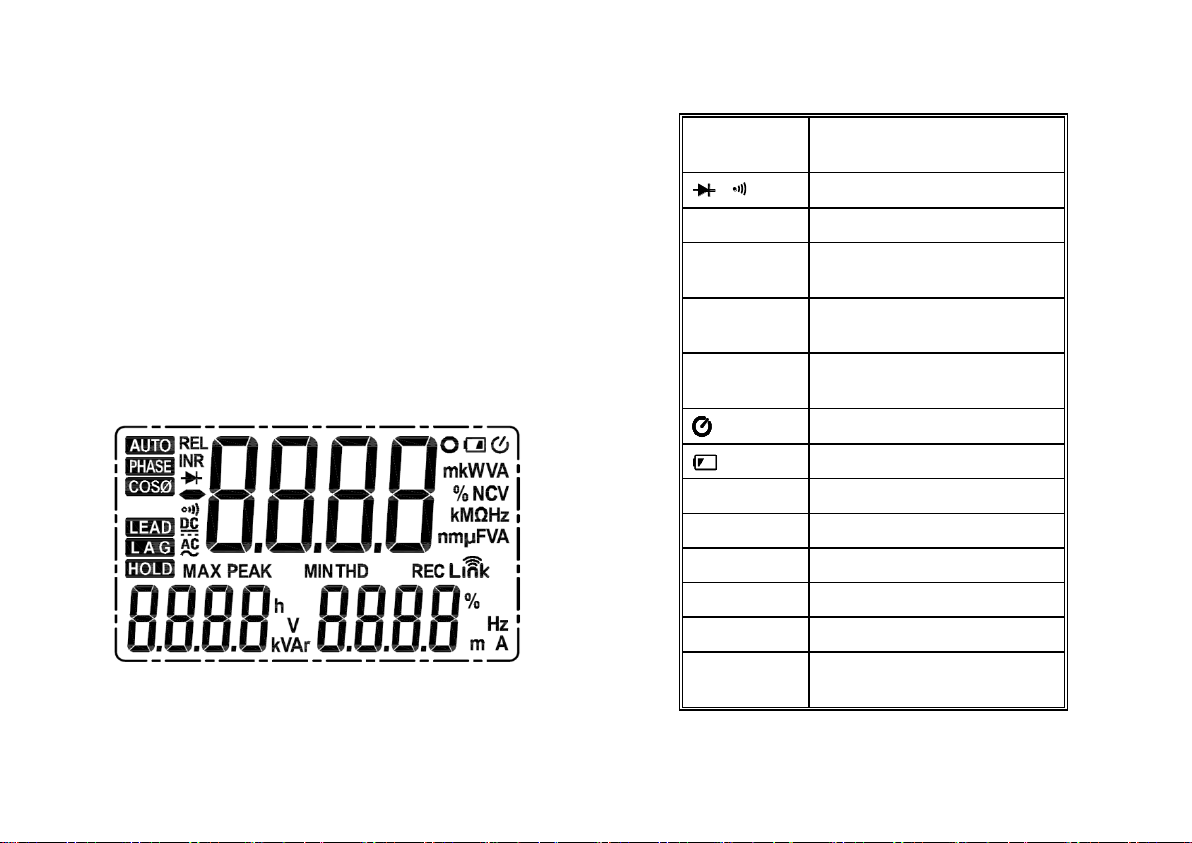
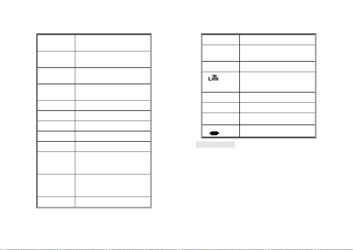
2.3 LCD display
AC, DC
Alternating current/Direct
current
.
Diode and continuity
AUTO
Auto range mode
MAX
Status of maximum
measurement
MIN
Status of minimum
measurement
REL
Status of relative
measurement
Status of automatic shutdown
LOW BATTERY
HOLD
Status of reading holding
HZ
Frequency measurement
%
Percentage (duty ratio)
mV, V
Millivolt, volt (voltage)
A
Ampere (electric current)
nF,μF, mF
Nano farad, microfarad and
millifarad
Page 11
21 22
Ω, kΩ, MΩ
Ohm, kilo-ohm and megohm
(resistance)
Hz, kHz,
MHZ
Hertz, kilohertz and
megahertz (frequency)
NCV
Non-contact voltage
detection
W, KW
Watt and kilowatt (active
power)
VA, KVA
Unit of apparent power
Var, KVAr
Reactive power
o
Phase angle
PEAK
Peak value measurement
THD
Total harmonic distortion
H01F
Total harmonic distortion F
(relative to fundamental
wave)
H01r
Total harmonic distortion r
(relative to actual effective
value)
COSФ
Power factor
Phase
Phase
INR
Status of inrush current
measurement
REC
Data recorder
Bluetooth function
LEAD
Leading phase angle
LAG
Lagging phase angle
h
Hour (time unit)
Negative sign
3. Specification
Recalibrate the meter under the conditions of
18°C~28°C and the relative humidity less than 75%,
with the calibration cycle of 1 year.
Page 12

23 24
3.1 General
Auto range and manual range.
Full-scale overload protection.
Maximum allowable voltage between measured
end and the ground: 1,000 V DC or 750 V AC.
Working height: less than 2,000 m.
Displayer: LCD.
Maximum displayed value: 5999 dgt.
Polar indication: self-indicating, "-" means
negative polarity.
Over-range display: '0L' or '-0L'.
Sampling time: around 3 times/s.
Unit display: display the functions and the unit
of electric quantity.
Time of automatic shutdown: 30 minutes.
Power supply: DC power supply 9 V.
Type of battery: NEDA 1604 or 6F22.
Under-voltage indication of battery: LCD
display symbol.
Temperature coefficient: less than 0.1×degree
of accuracy/°C.
Working temperature: 18°C~28°C.
Storage temperature: -10°C~50°C.
Dimension: 238×92×50 mm.
Weight: around 420 g (including battery).
3.2 Technical specifications
Environmental temperature: 235°C relative
humidity: ≤ 75%
Page 13
25 26
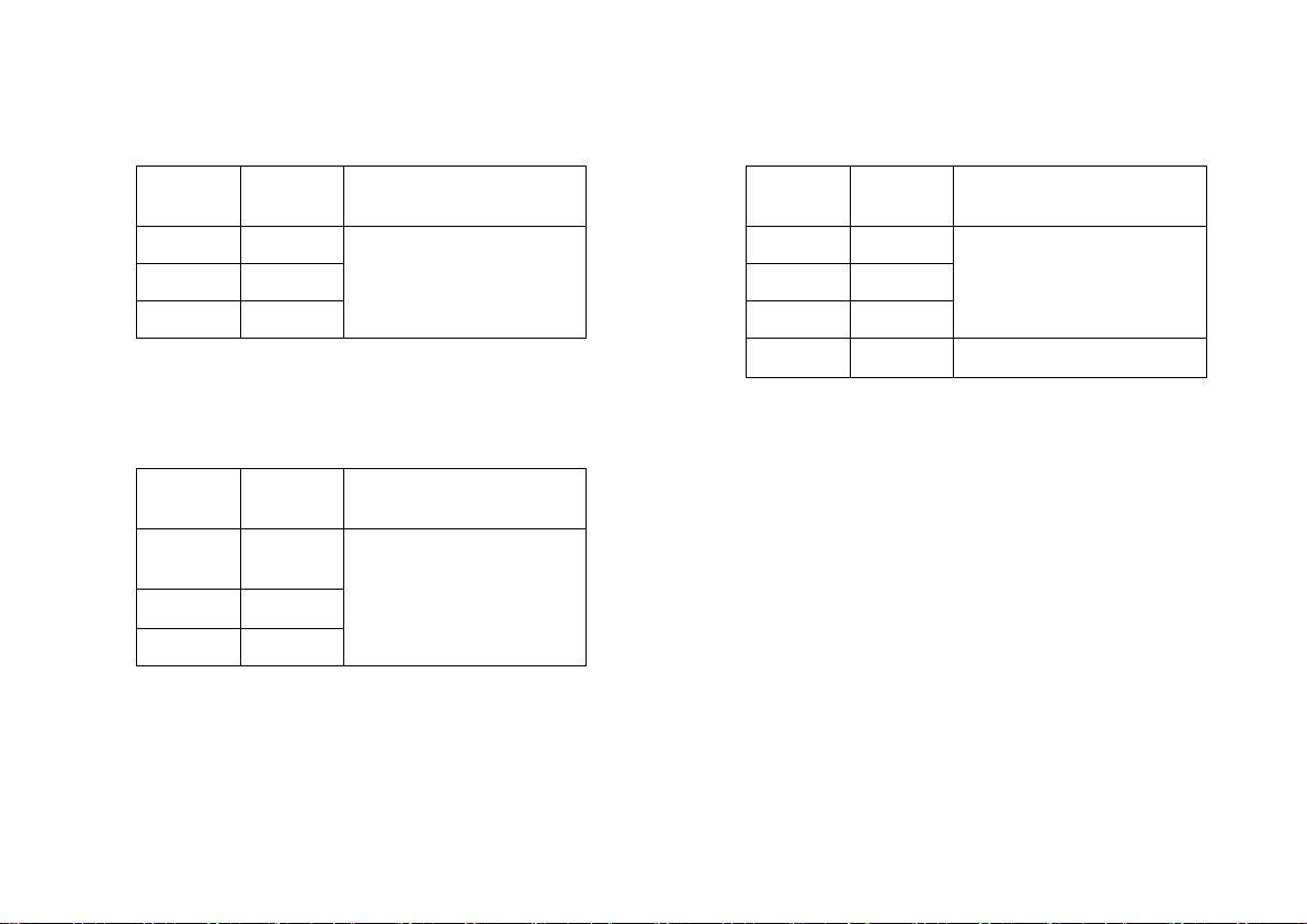
3.2.1 Alternating current
Range
Resolutio
n
Accuracy
60A
0.01A
(2.0% rdg+ 8 dgt)
600A
0.1A
1000A
1A
- Maximum input current: 1,000A AC
- Frequency range: 40~400 Hz
3.2.2 Inrush current
Range
Resolutio
n
Accuracy
60A
0.01A
< 60 A (for reference
only)
600A
0.1A
(5% rdg+ 60 dgt)
1000A
1A
Integral time: 100 ms; measurement range:
20~1,000 A; frequency range: 40~400 Hz
3.2.3 DC voltage
Range
Resoluti
on
Accuracy
6V
0.001V
(0.5% rdg+ 5 dgt)
60V
0.01V
600
0.1V
1000V
1V
(0.8% rdg+ 4 dgt)
- Input impedance: 10M
- Maximum input voltage: 750 V AC (effective value)
or 1,000 V DC.
Page 14

27 28
3.2.4 AC voltage
Range
Resoluti
on
Accuracy
6V
0.001V
(0.6% rdg+ 4 dgt)
60V
0.01V
600V
0.1V
750V
1V
(0.8% rdg+ 4 dgt)
- Input impedance: 10M
- Maximum input voltage: 750 V AC (effective
value) or 1,000 V DC.
- Frequency range: 40~400 Hz.
Note:
Under the small voltage range, there might be
reading on the meter before the probe is connected
to the measured circuit.
The above phenomenon is normal because the
meter has high sensitivity and it has no influence on
the actual measurement result.
3.2.5 Frequency
3.2.5.1 Frequency measurement with clamp (at
A gear):
Range
Resolutio
n
Accuracy
99.99Hz
0.01Hz
999.9Hz
0.1Hz
(1.5% rdg+ 5 dgt)
- Measurement range: 10 Hz~1 kHz
- Range of input signal: ≥ 20A AC (the input current
is increased with the measured frequency)
- Maximal input current: AC 1000 A (effective value)
Page 15

29 30
3.2.5.2 At V gear:
Range
Resolutio
n
Accuracy
99.99Hz
0.01Hz
999.9Hz
0.1Hz
(1.5% rdg+ 5 dgt)
9.999kH
z
0.001kHz
- Measurement range: 10 Hz~10kHz
- Range of input voltage: ≥ 1 V AC (effective value)
(the input voltage is increased with the measured
frequency)
- Input impedance: 10M
- Maximum input voltage: 750 V AC (effective
value)
3.2.5.3 At HZ/DUTY gear:
Range
Resolutio
n
Accuracy
9.999Hz
0.001Hz
(0.3% rdg+ 5 dgt)
99.99Hz
0.01Hz
999.9Hz
0.1Hz
9.999kH
z
0.001kHz
99.99KH
Z
0.01kHZ
999.9KH
Z
0.1KHZ
9.999M
HZ
0.001MH
Z
- Overload protection: 1,000 V DC or 750 V AC
(effective value)
- Range of input voltage: ≥ 2 V (the input voltage
is increased with the increase of the measured
frequency)
Page 16

31 32
3.2.6 Duty ratio
Range
Resolutio
n
Accuracy
0.1 - 99.9%
0.1%
(3.0%+3)
3.2.6.1 At A gear (from the clamp):
- Frequency response: 10 ~ 1 kHz.
- Range of input current: ≥ 20 A AC (effective value)
-Maximal input current: AC 1,000 A
3.2.6.2 At V gear:
- Frequency response: 10 ~ 10kHz.
- Range of input voltage: 1 V AC.
- Input impedance: 10M
- Maximum input voltage: 750 V AC (effective
value)
3.2.6.3 At HZ/DUTY gear:
- Frequency response: 10 ~ 10MHz.
- Range of input voltage: ≥ 2V AC (effective value)
(the input voltage is increased with the measured
frequency)
- Maximum input voltage: 250V AC (effective value)
3.2.7. Resistance
Range
Resolution
Accuracy
600
0.1
(0.8% rdg+ 3 dgt)
6k
0.001k
60k
0.01k
600k
0.1k
6M
0.001M
(2% rdg+ 5 dgt)
60M
0.1M
- Open-circuit voltage: around 0.78 V
- Overload protection: 1,000 V DC or AC (effective
value)
Page 17

33 34
3.2.8 Circuit continuity test
Range
Resolut
ion
Function
600Ω
0.1
If the resistance of
measured circuit is less
than 50, the buzzer inside
the meter will send a sound.
- Open-circuit voltage: around 1.48V
- Overload protection: 1,000 V DC or 750 V AC
(effective value)
3.2.9. Capacitance
Range
Resolutio
n
Accuracy
9.999nF
0.001nF
(3.0% rdg+ 5 dgt)
99.99nF
0.01nF
999.9nF
0.1nF
9.999F
0.001F
99.99F
0.01F
(3.0% rdg+ 5 dgt)
999.9F
0.1F
9.999mF
0.001mF
99.99mF
0.01mF
- Overload protection: 1,000 V DC or 750 V AC
(effective value)
3.2.10 Diode test
Range
Resoluti
on
Function
3V
0.001V
Display the approximate
value of diode forward
voltage
Page 18

35 36
- DC forward current is around 1 mA
- DC reverse voltage is around 3.2 V
- Overload protection: 1,000 V DC or 750 V AC
(effective value)
3.2.11 Single-phase active power
Range
Resoluti
on
Accuracy
3W
0.01W
(3.0% rdg+ 5 dgt)
100W
0.1W
4000W
1W
10kW
0.01kW
100kW
0.1kW
750kW
1kW
Minimum input current: 1 mA, and minimum input
voltage: 1 V.
3.2.12 Single-phase apparent power
Range
Resoluti
on
Accuracy
3VA
0.01VA
(3.0% rdg+ 5 dgt)
(3.0% rdg+ 5 dgt)
100VA
0.1VA
4000VA
1VA
10kVA
0.01kVA
100kVA
0.1kVA
750kVA
1kVA
Minimum input current: 1 mA, and minimum input
voltage: 1 V.
Page 19

37 38
3.2.13 Single-phase reactive power
Range
Resoluti
on
Accuracy
3W
0.01W
(3.0% rdg+ 5 dgt)
100W
0.1W
4000W
1W
10kW
0.01kW
100kW
0.1kW
750kW
1kW
Minimum input current: 1 mA, and minimum input
voltage: 1 V.
3.2.14 Power factor
Range
Resolution
Accuracy
0.3 ~ 1
capacitive
0.001
(3.0% rdg+ 5
dgt)
0.3 ~ 1
inductive
0.001
Min. input current: 1 mA / min. input voltage: 1 V.
3.2.15 Harmonics measurement
Range
Accuracy of harmonic electrical
level
1
(3.0% rdg+ 10 dgt)
2-6
(3.5% rdg+ +10 dgt)
7-8
(4.5% rdg+ 10 dgt)
9-10
(5.0% rdg+ 10 dgt)
11-15
(7.0% rdg+ 10 dgt)
16-20
(10.0% rdg+ 10 dgt)
Minimum input current: 1 mA, and minimum input
voltage: 1 V.
4 Operation Guide
4.1 Reading holding
1) During the measurement, if the reading shall be
held, short-press the "HOLD/B.L" key to lock the
display value of the display, and short-press the
"HOLD/B.L" key to unlock the kept reading.
Page 20

39 40
4.2 Manual range
The RANGE key is used for setting the auto/manual
range, and this key can be activated through
triggering. Its startup default state is
auto range. Press the key once to switch to the
manual range. In the manual range mode, move the
meter to the next higher gear after pressing the key
once, and after moving to the highest gear, press
the key continuously to move the meter to the lowest
gear. Perform the cyclic operations in sequence. If
press the key for more than 2 s,
the meter will be switched to the state of auto range.
Note:
During the measurement of diode, continuity test,
capacitance, and frequency KW, W and NCV gear,
the manual range is unavailable.
4.3 Switchover of frequency and duty ratio
1) When the meter is at AC current gear, short-press
the "Hz/%/INRUSH/▲" key, the meter can be in Hz
measurement state to measure the frequency of
measured AC voltage and current signals. Then,
short-press the "Hz/%/INRUSH/▲" key again, the
meter will be in DUTY measurement state to
measure the duty ratio of measured voltage and
current signals. If the meter is in HZ/% gear, shortpress "Hz/%/INRUSH/▲" key to switch the meter to
the HZ and DUTY states circularly.
2) If the meter is in AC current and AC/DC voltage
gear, short-press the "Hz/%/INRUSH/▲" key, the
meter will be in the voltage and current
measurement state.
Page 21

41 42
4.4 Selection of maximum/minimum value
measurement
1) Press the "MAX/MIN" key in the kW and W gear,
the interface will simultaneously display the
maximum and minimum values obtained after the
test for a period of time, and then press the ▲or
▼key on this interface to enter the interface
displaying the time of record. After that, the specific
time period of these maximum and minimum values
will be displayed.
2) When the meter is at AC current gear, AC/DC
voltage gear and resistance gear, press the
"MAX/MIN" to enter the MAX mode and measure
the maximum value all the time; press "MAX/MIN"
key once again to enter the state for measuring the
minimum value; and then press the "MAX/MIN" key
for the third time to exit the measurement mode of
maximum and minimum value.
Note:
1) The meter is in manual range mode under the
measurement states of max/min value.
4.5 Function switching
1) Long-press the FUNC key in the power
measurement interface to enter the power, voltage
and current measurement interface.
2) Short-press the FUNC key in the power
measurement interface to enter the active power,
apparent power, reactive power, power factor and
phase angle measurement interface.
3) When the meter is at power gear, short-press the
FUNC key in the voltage measurement interface to
enter the voltage effective value, harmonic,
harmonic distortion rate THD-R and harmonic
distortion rate THD-F measurement interface.
Page 22

43 44
4) When the meter is at power gear, short-press the
FUNC key in the current measurement interface to
enter the current effective value, harmonic,
harmonic distortion rate THD-R and harmonic
distortion rate THD-F measurement interface.
5) When the meter is at DC/AC gear, short-press the
FUNC key to switch between the DC voltage
measurement and AC voltage measurement
interface.
6) When the meter is at
resistance/diode/buzzer/capacitance gear, shortpress the FUNC key to switch among resistance,
diode, buzzer and capacitance measurement.
4.6 Measurement of relative value
1) Short-press the LINK/REL/▼ key at AC current,
AC/DC voltage and capacitance gears to enter the
relative value measurement mode and store the
current displaying value in memory as the reference
value. For the sequent measurement, the displayed
value is the difference value between the input value
and reference value, i.e. REL△ (current reading) =
input value - reference value.
2) This function of relative value measurement
only can be available in the manual measurement
mode.
4.7 LINK measurement
At any gear (excluding OFF gear), long-press
LINK/REL/▼ to turn on the Bluetooth of meter. Then
open the corresponding APP (iOS or Android) of the
meter through mobile phone or other equipment and
search the signal to link them. After the linking, the
APP will display the content displayed on meter in
Page 23

45 46
real time. Long-press the LINK/REL/▼ key once
again, the Bluetooth of meter will be turned off and
the meter will be disconnected from the APP.
4.8 REC function
The meter performs the functions of data recording
and Bluetooth data reading.
1) Data recording: the meter can save 1,000 pieces
of data records. Long-press REC/RANG key to
enable the meter to record data. The REC indicator
on LCD will be on, and the meter will store the
current measurement data at the rate of 3 times/s.
Long-press REC key again to exit the data
recording function. The meter also can exit the data
recording function when the 1,000 pieces of data
are recorded or a key operation or gear switching
operation is performed.
2) Data reading: the meter cannot support the direct
reading of stored data, and it only support the
reading of the stored data with the Bluetooth
function through a specific APP on the mobile phone.
4.9 ▼function
Short-press LINK/REL/▼ in the harmonic
measurement interface at KW and W gears to scroll
down, and to switch between the 1st harmonic and
20th harmonic. At the KW and W gears, short-press
the function key in the maximum/minimum value
measurement interface to scroll down, and switch
and display the maximum/minimum value.
4.10 ▲function
Short-press in the harmonic measurement interface
at KW and W gears to scroll up, and to switch
between the 1st harmonic and 20th harmonic. At the
KW and W gears, short-press the function key in the
maximum/minimum value measurement interface to
scroll up, and switch and display the
maximum/minimum value.
Page 24

47 48
4.11 INRUSH measurement
Long-press "Hz/%/INRUSH/▲" for more than 2 s at
AC current gear to enterthe inrush measurement
state.
4.12 Back-light and clamp lighting
1) During measurement, if the ambient light is too
dim to read, press
the "B.L/HOLD" for more than 2 s to turn on the
back-light, and the back-light will be off 20 s later.
2) In this period, press the "B.L/HOLD" key for 2 s
to turn off the back-light.
3) Turn on the back-light of the meter at the current
gear, and the clamp lamp will be on at the same time.
The luminous object of the back-light is LED with
high working current.
Although this meter is set with timing circuit (with
time of 30 s),
the service life of battery will be shortened with
frequent use of back-light.
Therefore, you shall minimize the use of back-light
as far as possible under the unnecessary conditions.
Note:
When the battery voltage ≤ 7.2 V, the display will
display the symbol of " "(under-voltage).
However,
if the back-light is used, when the battery voltage ≥
7.2 V, the battery voltage is reduced due to high
working current, the display may display the symbol
" "(when the symbol of " " is displayed, the
measurement accuracy cannot be guaranteed).
Under such circumstance, the battery will not be
replaced until the symbol " "is displayed without
back-light.
Page 25

49 50
4.13 Automatic shutdown
1) After startup, in case of no operation within 30
minutes, the meter will enter the dormant state and
shut down automatically for saving electric energy.
There will be voice prompt (a prolonged blast) from
the buzzer 1 minute before shutdown, and then the
meter will shut down automatically.
2) After shutdown, press FUNC key and the meter
will resume operation.
3) If the "B.L/HOLD" key is pressed during startup,
the function of automatic shutdown will cancel
automatically.
4.14. Measurement preparation
1) Turn the change-over switch to power on the
meter. If the battery is in under-voltage state (the
voltage ≤ 7.2 V), the display will display the symbol
" ", and then the battery shall be replaced.
2) " " means that the input voltage or current shall
not be greater than the indicated value in order to
prevent
the internal circuit from damage.
3) Turn the change-over switch to the required
measurement function and range.
4) For wiring, connect the public testing line at first
and then connect the energized testing line. For
disconnecting,
remove the energized testing line at first.
4.15 AC current measurement
Warning
Electric shock.
Remove the probe from the meter before
measuring with the current clamp.
1) Turn the change-over switch to AC current gear.
At this time, the meter is in AC current measurement
state, and then the suitable range shall be selected.
Page 26

51 52
2) Hold the trigger, and open the clamp to clamp one
conductor of measured circuits.
3) Read the current value from LCD display.
Note:
1) If two or more circuits of the measured circuits are
clamped, the measurement result will be not correct.
2) In order to acquire the accurate reading,
the measured conductor shall be in the center
of clamp as far as possible.
3) " " means that the maximum AC input
current is 1,000 A.
4) When the reading is greater than 600.1 A
at 60 A/600 A, there will be the alarm sound
"beep" from the meter. When the reading is
greater than 620 A rms, the ACA will display
overload.
5) When the reading is greater than 1001 A at
1,000 A, there will be the alarm sound "beep"
from the meter. When the reading is greater
than 1,100 A rms, the ACA will display
overload.
Figure 1 Schematic Diagram for Current
Measurement at AC Gear
Page 27
53 54
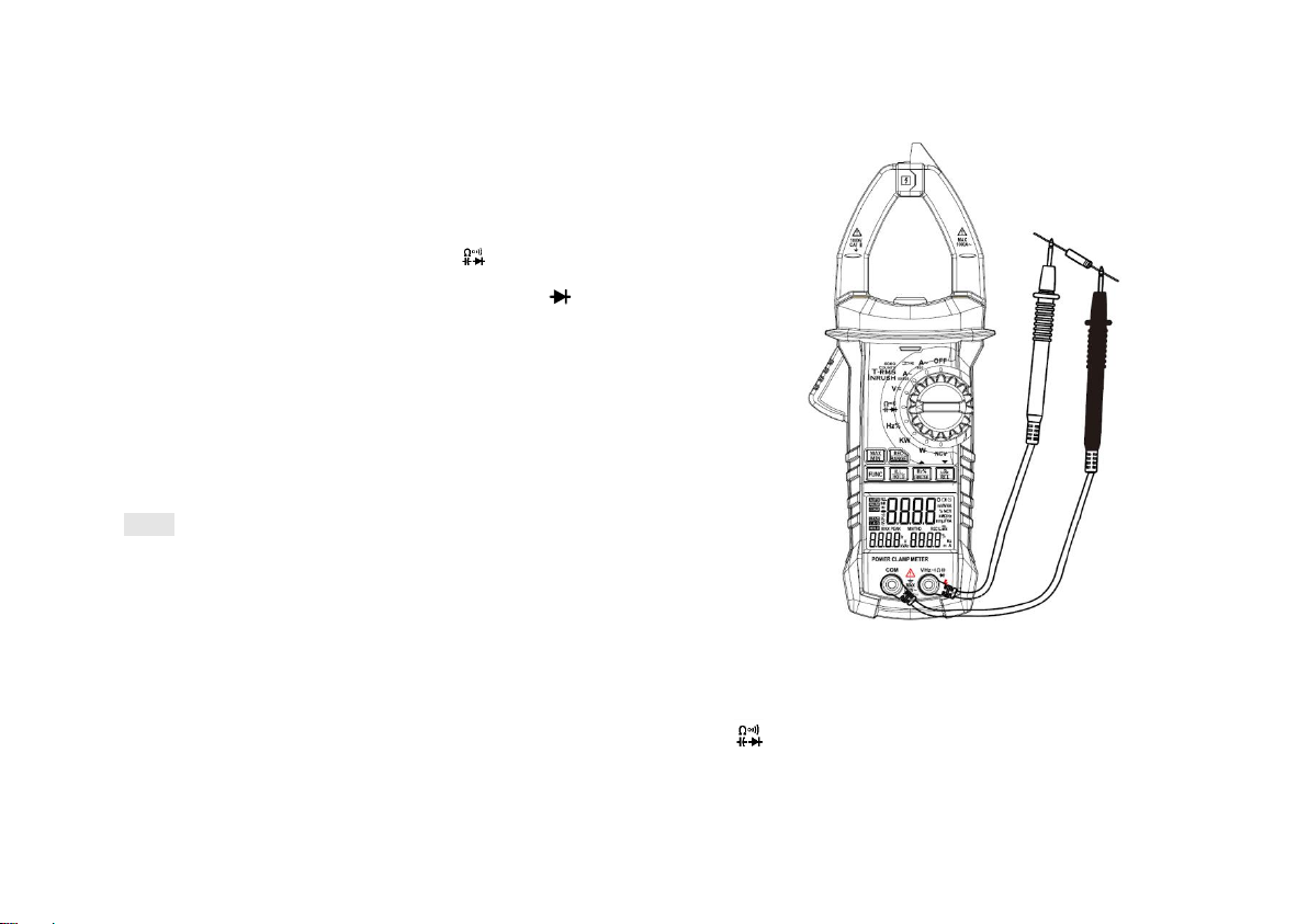
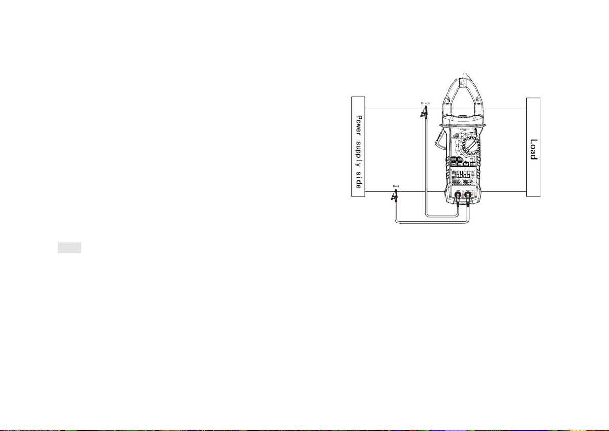
4.16. Voltage measurement
Warning
Electric shock.
Pay special attention to high voltage
measurement to avoid electric shock.
Do not input the voltage with the
effective value greater than AC 750.
1) Plug the black probe into COM jack, plug the red
probe into INPUT jack, and select the suitable
range.
2) Turn the change-over switch to AC/DC voltage
gear. In this case, the meter is in the DC voltage
measurement state. If the AC voltage shall be
measured, press the FUNC key and the meter will
enter the AC voltage measurement state.
3) Connect the probe to both ends of voltage source
or load to conduct measurement.
4) Read the voltage value from LCD.
Note:
1) The auto range will be unavailable under the
relative measurement mode.
2) " " means that the maximum input voltage is
750 V AC or 1,000 V DC.
3) There will be the alarm sound "beep" from the
meter, when the measured reading of the meter is
greater than 600 V rms ACV.
When the reading is greater than 750 V rms ACV,
the meter will display overload.
4) There will be the alarm sound "beep" from the
meter, when the measured reading of the meter is
greater than 1,000 V rms DCV.
When the reading is greater than 1100V rms, the
DCV will display overload.
Page 28

55 56
Figure 2: Schematic Diagram for AC Voltage
Measurement at AC/DC Voltage Gear
4.17 Measuring frequency and duty ratio
1) Frequency measurement with clamp (at
current gear):
Warning
Electric shock.
Remove the probe from the meter before
measuring with the current clamp.
⑴Turn the change-over switch to AC current gear.
⑵Hold the trigger, and open the clamp to clamp one
conductor of measured circuits.
⑶ Press the "Hz/%INRUSH/▲"button shortly to
switch into the status of frequency measurement.
⑷Read the frequency value from LCD display.
⑸Press "Hz/%INRUSH/▲"again to enter the status
of duty ratio measurement.
Page 29

57 58
Note:
⑴If two or more circuits of the measured circuits are
clamped, the measurement result will be not correct.
⑵The measurement range of frequency is 10 Hz ~
1 kHz. If the measured frequency is less than 10 Hz,
the frequency greater than 10 kHz might be
measured, but the accuracy of measurement
cannot be guaranteed.
⑶The measurement range of duty ratio is 10 ~ 95%.
⑷The maximum input current of " " is 1000A AC
(effective value).
2) At voltage gear:
Warning
Electric shock.
Pay special attention to high voltage
measurement to avoid electric shock.
Do not input the voltage with effective value
greater than AC 750.
⑴Insert the black probe into COM jack, and insert
the red probe into INPUT jack.
⑵Turn the change-over switch to AC/DC voltage
gear, press FUNC to enter the status of AC voltage
measurement.
⑶Press the "Hz/%INRUSH/▲"button to switch into
the frequency measurement state.
⑷Connect the probe to both ends of signal source
or load to conduct measurement.
⑸Read on the LCD.
⑹Press "Hz/%INRUSH/▲"again to enter the status
of duty ratio measurement.
Note:
⑴The measurement range of frequency is 10 Hz ~
10kHz. If the measured frequency is less than 10 Hz,
the LCD will display "00.0", the frequency less than
10 kHz might be measured, but the accuracy of
measurement cannot be guaranteed.
⑵The measurement range of duty ratio is 10 ~ 95%.
Page 30

59 60
⑶The maximum input voltage of " " is 750 V AC
(effective value).
3) At HZ/DUTY gear:
Warning
Electric shock.
Pay special attention to high voltage
measurement to avoid electric shock.
Do not input the voltage with effective value
greater than AC 750 V.
⑴Insert the black probe into COM jack, and insert
the red probe into INPUT jack.
⑵Turn the change-over switch to HZ% gear.
⑶Connect the probe to both ends of signal source
or load to conduct measurement.
⑷Read on the LCD.
⑷Press "Hz/%INRUSH/▲"again to enter the status
of duty ratio measurement.
Note:
The measurement range of frequency is 10 Hz ~
9.999 MHz, if the measured frequency less than 10
Hz,
the LCD will display "00.0"; the frequency greater
than 9.999 MHz might be measured, but the
accuracy of measurement cannot be guaranteed.
Figure 3: Schematic Diagram for Frequency
Measurement at HZ% Gear
Page 31

61 62
4.18 Resistance measurement
Warning
Electric shock.
When measuring the impedance on the
circuit, the circuit power should be
disconnected, and the capacitor in the
circuit should be completely discharged.
1) Insert the black probe into COM jack, and insert
the red probe into INPUT jack.
2) Place the change-over switch on the gear,
and set the meter in the status of resistance
measurement.
3) Connect the probes to both ends of the
measured resistor or the circuit for measurement.
4) Read on the LCD.
Note:
1) When the input is open-circuited, the LCD will
display "0L" for over range.
2) If the resistance of measured resistor is greater
than 1 MΩ, the reading of the meter might be stable
after a few seconds, and it is common for the high
resistance readings.
Figure 4 Schematic Diagram for Resistance
Measurement at Gear
Page 32
63 64
4.19 Diode test
1) Insert the black probe into COM jack, and insert
the red probe into INPUT jack.
2) Turn the change-over switch to the gear.
3) Press "FUNC" to switch into the status of
measurement.
4) Connect the red probe to the positive pole of the
diode, and connect the black probe to the negative
pole for measurement.
5) Read on the LCD.
Note:
1) The approximate value of the forward voltage
drop of diode will be displayed on the meter.
2) If the probe is connected inversely or the probe is
open-circuited, the LCD will display "0L".
Figure 5 Schematic Diagram for Diode Testing at
Gear
Page 33

65 66
4.20 Circuit continuity test
Warning
Electric shock.
For the circuit continuity test, the circuit
power should be disconnected, and the
capacitor in the circuit should be
completely discharged.
1) Insert the black probe into COM jack, and insert
the red probe into INPUT jack.
2) Turn the change-over switch to the gear.
3) Press "FUNC" button to switch to the status of
circuit continuity testing.
4) Connect the probes to both ends of the circuit for
measurement.
5) If the resistance of measured circuit is less than
50, the buzzer inside the meter will make a sound.
6) Read the resistance value of the circuit from LCD.
Note:
If the probe is open-circuited or the resistance of the
measured circuit is greater than 600, the "0L" will
be displayed.
Figure 6 Schematic Diagram for Circuit Continuity
Test at Gear
Page 34

67 68
4.21 Capacitance measurement
Warning
Electric shock.
To avoid electric shock, the capacitor
should be completely discharged before
the capacitance measurement.
1) Insert the black probe into COM jack, and insert
the red probe into INPUT jack.
2) Turn the change-over switch to the gear.
3) Connect the probe to the both ends of the
measured capacitor for measurement after the
capacitor is completely discharged.
4) Read the capacitance value from LCD.
Note:
To improve the accuracy of the measured value less
than 10 nF,the distributed capacitance of the meter
and conductors should be subtracted.
Figure 7 Schematic Diagram for Capacitance
Measurement at Gear
Page 35

69 70
4.22 Measurement of inrush current
Warning
Electric shock.
Remove the probe from the meter before
measuring with the current clamp.
4.10.1 Turn the change-over switch to 60/600 A or
1000 A AC current gear.
4.10.2 Hold the trigger, and open the clamp to clamp
one conductor of measured circuits.
4.10.3 Long press the "HZ%/INRUSH/▲" button
more than 2 seconds to enter the mode of inrush
current measurement. Then the LCD will display
"INR", and the meter will display and hold the inrush
current value until the motor start-up is detected.
4.10.4 Read the inrush current value from LCD
display.
Note:
1) If two or more circuits of the measured circuits are
clamped, the measurement result will be not correct.
2) In order to acquire the accurate reading, the
measured conductor shall be in the center of clamp
as far as possible.
3) The LCD only displays "OL" in the manual range
mode indicating the over range, and the higher
range should be selected.
4) Under the manual range mode, if the measured
value is not known in advance, the highest level
should be set for the range.
5) " " means that the maximum input current is
1000A AC (effective value).
Page 36

71 72
Figure 8 Schematic Diagram for Inrush Current
Measurement at AC Current Gear
4.23 NCV measurement
1) Turn the change-over switch of the meter to the
NCV gear.
2) The top of the meter should be arranged near the
conductor. When the detected voltage is great than
110 Vac (RMS), the voltage sensing indicator may
be on, and the buzzer may make the alarm sound
"beep".
Note:
1: The voltage may still exist even without
instructions. Do not determine whether there is
voltage in the conductor only by using the noncontact voltage detectors. The detecting operation
might be affected by the socket design, insulation
thickness, type and other factors.
2: When there is input voltage to the input terminal
of the meter, the voltage sensing indicator may also
be on.
Page 37

73 74
3: Intrusive sources (such flashlight, motor, etc.) in
the external environment may cause a wrong trigger
of non-contact voltage detection.
Figure 9 Schematic Diagram for Voltage Detection
at NCV Gear
4.24 Active power measurement
Warning
Electric shock.
Pay special attention to high voltage and high
current measurement to avoid electric shock.
Do not input the voltage with the effective
value greater than AC 750 and the current with
the effective value greater than 1,000 A.
1) Turn the change-over switch to kW or W gear.
2) Clamp the measured conductor of the power
supply or load with the clamp. Input the measured
voltage from the V end and COM end. After the
measuring circuits are connected correctly, the
active power shall be read from the LCD and the
LCD displays the effective values of measured
voltage and current simultaneously.
Page 38

75 76
3) Determine whether the switch shall be turned to
the KW gear or W gear according to the measured
current. At the W gear, the measurement range of
current is 1 mA - 4,000 mA and at the KW gear, the
measurement range of current is 1 A - 1,000 A. The
measurement range of voltage at both the KW gear
and W gear is 1 V -750 V.
4) Press MAX/MIN key in the active power
measurement interface to enter the
maximum/minimum value measurement mode, and
the LCD will display the measured value of active
power and the maximum and minimum values of
active power within a certain period simultaneously.
Press the Hz/%INRUSH/▲ key or LINK/REL/▼ key
again in this interface, the LCD will display the
recording time and real-time measurement value of
active power.
Note:
1)The maximum measurement range of active
power is 750 kW, and the LCD will display OL for
over range.
2)The maximum measured current is 4,000 mA at
W gear. Please do not operate by mistake.
3)The minimum measured voltage is 1 V and the
minimum measured current is 1 mA.
4)The maximum measured voltage is 750 V and
the maximum measured current is 1,000 A.
Page 39

77 78
Figure10 Schematic Diagram for Active Power
Measurement at KW Gear
4.25 Apparent power measurement
Warning
Electric shock.
Pay special attention to high voltage and high
current measurement to avoid electric shock.
Do not input the voltage with the effective
value greater than AC 750 and the current with
the effective value greater than 1,000 A.
1) Turn the change-over switch to the kW or W gear,
press FUNC key to enter the apparent power
measurement interface.
2) Clamp the measured conductor of the power
supply or load with the clamp. Input the measured
voltage from the V end and COM end. After the
measuring circuits are connected correctly, read the
apparent power from the LCD and the LCD displays
the effective values of measured voltage and
current simultaneously.
3) Determine whether the switch shall be turned to
the KW gear or W gear according to the measured
current. At the W gear, the measurement range of
current is 1 mA - 4,000 mA and at the KW gear, the
measurement range of current is 1 A - 1,000 A. The
measurement range of voltage at both the KW gear
and W gear is 1 V -750 V.
4) Press MAX/MIN key in the apparent power
measurement interface to enter the
maximum/minimum value measurement mode, and
Page 40

79 80
the LCD will display the measured value of apparent
power and the maximum and minimum values of
apparent power within a certain period
simultaneously. Press the Hz/%INRUSH/▲ key or
LINK/REL/▼ key once again in this interface. The
LCD will display the recording time and real-time
measurement value of apparent power.
Note:
1) The maximum measurement range of apparent
power is 750 kW, and the LCD will display OL for
over range.
2) The maximum measured current is 4,000 mA at
W gear. Please do not operate by mistake.
3) The minimum measured voltage is 1 V and the
minimum measured current is 1 mA.
4) The maximum measured voltage is 750 V and the
maximum measured current is 1,000 A.
Figure11 Schematic Diagram for Apparent Power
Measurement at KW Gear
Page 41

81 82
4.26 Power factor measurement
1)Turn the change-over switch to the kW or W gear,
press FUNC key to enter the power factor
measurement interface.
2)Clamp the measured conductor of the power
supply or load with the clamp. Input the measured
voltage from the V end and COM end. After the
measuring circuits are connected correctly, the
power factor from the LCD shall be read and the
LCD displays the value of reactive power
simultaneously.
3)Determine whether the switch shall be turned to
the KW gear or W gear according to the measured
current. At the W gear, the measurement range of
current is 1 mA - 4,000 mA and at the KW gear, the
measurement range of current is 1 A - 1,000 A. The
measurement range of voltage at both the KW gear
and W gear is 1 V -750 V.
4)There is a phase difference between the voltage
value and current value of the inductive load and
capacitive load. Generally. the power factor is
indicated by the cosine COSǾ of phase angle Ǿ.
When the power factor is negative, it means that the
measured load is capacitive load.
5) The reactive power is an indirectly measured
value. The computational formula of kVAr is:
222
k kWkVAVAr −=
, and the value is calculated out
with the measured voltage, current
and active power value.
Warning
Electric shock.
Pay special attention to high voltage and high
current measurement to avoid electric shock.
Do not input the voltage with the effective value
greater than AC 750 and the current with the
effective value greater than 1,000 A.
Page 42

83 84
Note:
1) The maximum measured current is 4,000 mA at
W gear. Please do not operate by mistake.
2) The minimum measured voltage is 1 V and the
minimum measured current is 1 mA.
3) The maximum measured voltage is 750 V and the
maximum measured current is 1,000 A.
Figure12 Schematic Diagram for Power Factor
Measurement at KW Gear
4.27 Phase angle measurement
1) Turn the change-over switch to the kW or W gear,
press FUNC key to enter the phase angle
measurement interface.
2) Clamp the measured conductor of the power
supply or load with the clamp. Input the measured
voltage from the V end and COM end. After the
measuring circuits are connected correctly, the
phase angle shall be read from the LCD and the
LCD displays the effective values of measured
voltage and current simultaneously.
Warning
Electric shock!
Pay special attention to high voltage and
high current measurement to avoid
electric shock.
Page 43
85 86
3) Determine whether the switch shall be turned to
the KW gear or W gear according to the measured
current. At the W gear, the measurement range of
current is 1 mA - 4,000 mA and at the KW gear, the
measurement range of current is 1 A - 1,000 A. The
measurement range of voltage at both the KW gear
and W gear is 1 V -750 V.
4) There is a phase difference between the voltage
vale and current value of the inductive load and
capacitive load. Generally, the phase difference is
indicated by the phase angle Ǿ.
Note:
1) The maximum measured current is 4,000 mA at
W gear. Please do not operate by mistake.
2) The minimum measured voltage is 1 V and the
minimum measured current is 1 mA.
3) The maximum measured voltage is 750 V and the
maximum measured current is 1,000 A.
Figure 13 Schematic Diagram for Phase Angle
Measurement at KW Gear
Page 44
87 88
4.28 Harmonics measurement (voltage signal)
1)Turn the change-over switch to the kW or W gear,
first long-press the FUNC key to enter the voltage
measurement interface, and then short-press the
FUNC key to enter the harmonics measurement
interface, and switch from 1st - 20th harmonic through
pressing the Hz/%INRUSH/▲ key or LINK/REL/▼
key.
2)Input the measured voltage signal from the V end
and COM end.
3)After the measuring circuits are connected
correctly, the effective value of the nth harmonic
component shall be read.
4)Short-press the FUNC key in the harmonic
measurement interface once again to enter into THDR (relative to the actual effective value) or THD-F
(relative to the fundamental wave) measurement
mode. The main interface displays the effective value
of the nth harmonic component and the minor
interface displays the total harmonic distortion.
5)Press MAX/MIN key in the voltage measurement
interface to enter the maximum/minimum value
measurement mode. In this case, the main interface
displays the measured effective value of voltage and
the minor interface displays the maximum and
minimum values within a certain period. Press the
Hz/%INRUSH/▲ key or LINK/REL/▼ key again in this
interface to enter into the time recording interface. In
this case, the main interface displays the limited
voltage measurements, and the minor interface
displays the time of maximum and minimum values.
Warning
Electric shock.
Pay special attention to high voltage
measurement to avoid electric shock.
Do not input the voltage with the effective
value greater than AC 750.
Page 45

89 90
Note:
1)The minimum measured voltage is 1 V and the
maximum measured voltage is 750 V. This interface
will display OL for over 750 V.
Figure 14 Schematic Diagram for Harmonics
Measurement of Voltage Signal at KW Gear
Page 46

91 92
4.29 Harmonics measurement (current signal)
1) Turn the change-over switch to the kW or W gear,
first long-press the FUNC key to enter the current
measurement interface, and then short-press the
FUNC key to enter into the harmonics measurement
interface, and switch from 1st - 20th harmonic
through pressing the Hz/%INRUSH/▲ key or
LINK/REL/▼ key.
2) Clamp the measured conductor of the power
supply or load with the clamp.
3) After the measuring circuits are connected
correctly, the effective value of the nth harmonic
component shall be read.
4) Short-press the FUNC key in the harmonic
measurement interface once again to enter into
THD-R (relative to the actual effective value) or
THD-F (relative to the fundamental wave)
measurement mode. The main interface displays
the effective value of the nth harmonic component
and the minor interface displays the total harmonic
distortion.
5) Press MAX/MIN key in the current measurement
interface to enter the maximum/minimum value
measurement mode. In this case, the main interface
displays the measured effective value of current and
the minor interface displays the maximum and
minimum values within a certain period. Press the
Hz/%INRUSH/▲ key or LINK/REL/▼ key again in
this interface to enter into the time recording
interface. In this case, the main interface displays
the limited voltage measurements, and the minor
interface displays the time of max. and min. values.
Warning
Electric shock.
Pay special attention to high current
measurement to avoid electric shock.
Do not input the current with the effective
value greater than AC 1,000 A.
Page 47

93 94
Note:
1)The minimum measured current is 1 mA and the
maximum measured current is 1,000 A. This
interface will display OL for over 1,000 A.
Figure 15 Schematic Diagram for Harmonics
Measurement of Current Signal at KW Gear
5 Maintenance
5.1 Battery replacement
Warning
Before opening the battery cover of meter,
take the probe away from the measuring
circuits to avoid electric shock.
1) If the meter displays the symbol " ", the battery
shall be replaced.
2) Unscrew the fastening screw of the meter battery
cover and remove it.
3) Replace the old battery.
4) Install the battery cover in the original position.
Note:
Do not install the battery in the incorrect direction.
Page 48

95 96
5.2 Probe replacement
Do not use the probe with damage or wear trace
(exposing the white layer). Otherwise, replace it
timely.
Warning
The replaced probe shall meet the EN61010031 Standard, rated CATI III 1,000 V, and the
range of current measurement shall be 10 A
or above.
The probe with damaged insulating layer and
exposed metal wire of conductor must be replaced.
6 Delivery scope
1 x Clamp meter PCE-PCM 3
1 x Transport bag
1 x Test lead set
1 x 9V block battery
1 x User manual
 Loading...