

Page 1

This publication, including all photographs, illustrations and
software, is protected under international copyright laws, with all
rights reserved. Neither this manual, nor any of the material
contained herein, may be reproduced without the express written
consent of the manufacturer.
The information in this document is subject to change without
notice. The manufacturer makes no representations or warranties
with respect to the contents hereof and specifically disclaims any
implied warranties of merchantability or fitness for any particular
purpose. Further, the manufacturer reserves the right to revise this
publication and to make changes from time to time in the content
hereof without obligation of the manufacturer to notify any person
of such revision or changes.
Trademarks
IBM, VGA, OS/2, and PS/2 are registered trademarks of
International Business Machines.
Intel, Pentium, Pentium-II, Pentium-III, MMX, and Celeron are
registered trademarks of Intel Corporation.
Microsoft, MS-DOS and Windows 95/98/NT are registered
trademarks of Microsoft Corporation.
Sound Blaster is a trademark of Creative Technology Ltd.
PC-cillin and ChipAwayVirus are trademarks of Trend Micro Inc.
AMI is a trademark of American Megatrends Inc.
A3D is a registered trademark of Aureal Inc.
Gamut is a registered trademark of Formosoft International Inc.
SuperVoice is a registered trademark of Pacific Image
Communications Inc.
MediaRing Talk is a registered trademark of MediaRing Inc.
Other names used in this publication may be trademarks and are
acknowledged.
Copyright © 2000
All Rights Reserved
M770LMRT
I81X/February 2000
2
, V1.2C
Page 2

Federal Communications Commission (FCC)
Federal Communications Commission (FCC)
Federal Communications Commission (FCC)Federal Communications Commission (FCC)
This equipment has been tested and found to comply with the limits for a
Class B digital device, pursuant to Part 15 of the FCC Rules. These limits
are designed to provide reasonable protection against harmful interference
in a residential installation. This equipment generates, uses, and can
radiate radio frequency energy and, if not installed and used in accordance
with the instructions, may cause harmful interference to radio
communications. However there is no guarantee that interference will not
occur in a particular installation. If this equipment does cause harmful
interference to radio or television reception, which can be determined by
turning the equipment off and on, the user is encouraged to try to correct
the interference by one or more of the following measures:
Reorient or relocate the receiving antenna.
Increase the separation between the equipment and the receiver.
Connect the equipment onto an outlet on a circuit different from that
to which the receiver is connected.
Consult the dealer or an experienced radio/TV technician for help.
Shielded interconnect cables and shielded AC power cable must be
employed with this equipment to insure compliance with the pertinent RF
emission limits governing this device. Changes or modifications not
expressly approved by the system’s manufacturer could void the user’s
authority to operate the equipment.
Declaration of Conformity
This device complies with part 15 of the FCC rules. Operation is subject
to the following conditions:
This device may not cause harmful interference, and
This device must accept any interference received, including
interference that may cause undesired operation.
Canadian Department of Communications
Canadian Department of Communications
Canadian Department of CommunicationsCanadian Department of Communications
This class B digital apparatus meets all requirements of the Canadian
Interference-causing Equipment Regulations.
Cet appareil numérique de la classe B respecte toutes les exigences du
Réglement sur le matériel brouilieur du Canada.
Page 3

Table of Contents
Chapter 1 Introduction.................................................................... 1
Key Features ..................................................................................... 2
Processors Support ....................................................................... 2
Memory Support........................................................................... 2
Expansion Slots ............................................................................ 2
Onboard IDE channels..................................................................2
Power Supply and Power Management........................................ 2
Built-in Graphics System..............................................................3
Sound System ............................................................................... 3
Onboard I/O Ports.........................................................................3
Hardware Monitoring ................................................................... 4
Built-in LAN Adapter................................................................... 4
Fax/Modem DAA Module............................................................ 4
Onboard Flash ROM ....................................................................4
Bundled Software ......................................................................... 4
Dimensions ................................................................................... 5
Package Contents .............................................................................. 5
Optional Accessories .................................................................... 5
Static Electricity Precautions ............................................................ 6
Chapter 2 Mainboard Installation ................................................... 7
Mainboard Components....................................................................8
I/O Ports ............................................................................................ 9
Install the Processor ..........................................................................9
Installing a Slot-1 Processor Cartridge ......................................... 9
Installing a Socket-370 Processor............................................... 11
Install Memory................................................................................ 11
Set the Jumpers ............................................................................... 12
Jumper JP1: Clear CMOS Memory............................................ 13
Jumper JP3: Keyboard Power On Selector................................. 13
Jumper JP4: Onboard Audio Enable/Disable ............................14
Jumper JP5: System Bus Frequency (100 MHz) Selector .......... 14
Jumper JP6: Audio Codec Selector ............................................ 14
Jumper JP7: Enable/Disable Onboard LAN...............................14
Jumper JP8: IDT or Intel processor Selector .............................. 14
Jumper JP9: System Bus Frequency (133 MHz) Selector (only for
i810e chipset).............................................................................. 15
Jumper JP12, JP13: Normal/Flexible setting for socket-370......15
Install the Mainboard ...................................................................... 16
Install the Extension Brackets.........................................................17
LAN Adapter Extension Bracket................................................ 17
Page 4

Fax/Modem DAA Module.......................................................... 18
Optional Extension Brackets........................................................... 19
Optic Module Extension Bracket................................................ 19
Internal Digital Audio................................................................. 19
AV/S-Video Output Extension Bracket...................................... 20
Install Other Devices....................................................................... 21
Floppy Disk Drive ...................................................................... 21
IDE Devices................................................................................ 21
Internal Sound Connections........................................................22
Infrared Port................................................................................ 22
Expansion Slots............................................................................... 22
AMR Slot ................................................................................... 23
Wake On LAN............................................................................ 24
Wake On Modem ....................................................................... 24
Chapter 3 BIOS Setup................................................................... 25
Introduction..................................................................................... 25
Running the Setup Utility ............................................................... 26
Standard CMOS Setup Page ........................................................... 27
Advanced Setup Page ..................................................................... 28
Power Management Setup Page...................................................... 30
PCI / Plug and Play Setup Page ......................................................31
Load Optimal Settings .................................................................... 32
Load Best Performance Settings ..................................................... 32
Features Setup Page ........................................................................ 33
CPU PnP Setup Page ...................................................................... 35
Hardware Monitor Page .................................................................. 36
Change Password ............................................................................ 36
Change or Remove the Password ............................................... 37
Exit.................................................................................................. 37
Chapter 4 Software & Applications.............................................. 38
Introduction..................................................................................... 38
Installing the Drivers....................................................................... 38
Installing Under Windows 95/NT/2000 .....................................38
Bus Master IDE Driver............................................................... 39
USB Driver................................................................................. 39
Sound Driver .............................................................................. 39
Graphics Drivers and Software................................................... 39
Modem Drivers and Software..................................................... 40
Network Adapter Driver............................................................. 40
BIOS Update Utility ................................................................... 40
PC-Cillin Software ..................................................................... 40
ADCM Software......................................................................... 40
Auto-Installing under Windows 98 ............................................ 40
Page 5

Using the PCI Sound Application ................................................... 42
The Four Speakers System.............................................................. 43
Speaker Installation .................................................................... 43
Speaker Position ......................................................................... 43
Mixer Setup ................................................................................ 43
Demo .......................................................................................... 44
Appendix A: Corel WordPerfect Suite 8 ................................... A1
Welcome to Corel WordPerfect Suite 8 ........................................ A2
Installing Corel WordPerfect Suite 8 ............................................ A6
Learning how to use Corel WordPerfect Suite 8 ........................... A9
Support and Services ................................................................... A13
Appendix B: Gamut .....................................................................B1
Introduction ................................................................................... B2
Before Installing ............................................................................ B3
Installation .................................................................................... B4
Produce MP3 fileUse CD-Cashier ............................................ B5
Play MP3 fileUse Musician ...................................................... B7
Play music CDUse 3D
Play MIDI fileUse Midier ......................................................... B9
Recording audio dataUse Voice-Catcher ................................ B10
FS
-ACD .................................................. B8
Page 6

Chapter 1
Introduction
This mainboard has a slot-1 processor socket for an Intel
processor cartridge, and it also has a socket-370 for an Intel
PPGA (Plastic Pin Grid Array) Celeron or FCPGA Pentium III
processor. You can install either one of these processors according
to the power and performance requirements that you need from
your system. Note that you cannot install two processors on this
mainboard.
Slot-1 processors include the SEPP (Single Edge Processor
Package) Celeron, the Pentium-II, and the Pentium-III. The
mainboard supports a system bus of 66 MHz, 100 MHz or 133
MHz (i810e chipset only).
The mainboard uses the Intel i810/i810e chipset which provides
CPU Plug & Play through firmware. The mainboard is highly
integrated and includes a built-in Graphics Accelerator with
optional AV/S-Video output, a built-in PCI 3D Sound System,
and a built-in 10BaseT/100BaseTX Network Adapter. A V.90
Fax/Modem DAA module is also shipped with the mainboard. In
addition, it has a full set of ATX I/O Ports and three expansion
slots.
This mainboard has all the features you need to develop a powerful
multimedia workstation that is network ready, and has built-in
communications. It supports hardware monitoring and built-in
trend’s ChipAwayVirus virus protection system. The board
adheres to the micro-ATX form factor and ATX power supply
which supports all of the ATX power management features
including ACPI (Advanced Configuration and Power management
Interface), power saving modes and keyboard power on hot
keys.
Page 7

Key Features
The key features of this mainboard include:
Processors Support
♦ Pentium-III support for 450 MHz to 800 MHz clock rates
♦ Pentium-II support for 233 MHz to 450 MHz clock rates
♦ SEPP Celeron support for 266 MHz to 433 MHz clock
rates
♦ PPGA Celeron provides Pentium-II performance with
integrated level 1 and level 2 cache memory
FCPGA Pentium-III CPUs are supported
♦
♦ Support for 66 MHz, 100 MHz and 133 MHz (i810e chipset
only) Front Side Bus
♦ All processors configured by CPU Plug & Play
Memory Support
♦ Two DIMM slots for SDRAM 168-pin memory modules
♦ Support for 100 MHz memory bus
♦ Maximum installed memory can be 2 x 256 MB = 512 MB
Expansion Slots
Three 32-bit PCI slots
♦
♦ One AMR slot
Onboard IDE channels
♦ Primary and Secondary PCI IDE channels
♦ Support for PIO (programmable input/output) modes
♦ Support for Bus mastering and UltraDMA 33/66 modes
(UltraDMA 66 is available with 82801AA chip only)
Power Supply and Power Management
♦ Provides ATX power connector
Support for Green PC standard, suspend switch, keyboard
♦
power on/off
Support Wake on Modem, Wake on LAN and Wake on
♦
Alarm
Page 8

Built-in Graphics System
♦ 3D Hyper Pipelined Architecture: Parallel Data Processing
(PDP) and Precise Pixel Interpolation (PPI).
♦ Full 2D H/W and Motion Video Acceleration
Up to 1600x1200 in 8-bit color at 85Hz refresh
♦
♦ H/W Motion Compensation Assistance for S/W MPEG2
decode
♦ Optional TV encoder for NTSC and PAL TV support (AV/S-
Video)
Sound System
♦ Meets PC98 audio specification
♦ Full duplex playback and recording with built-in 16-bit
CODEC
♦ HRTF 3D professional audio supports both Direct Sound
3D® and A3D® compatible interface plus support for 4-
channel speakers
Drivers support DOS/Windows 95/98/2000/NT 4.0
♦
Built-in 32 ohm earphone buffer and 3D surround
♦
♦ Provides MPU-401 Game/MIDI port and legacy Sound
Blaster 16 support
♦ Downloadable Wave-table Synthesizer supports Direct
Music®
♦ Digital Audio Interface (SPDIF In/Out) with 24-bit stereo,
44KHz sampling rate and measured 120dB audio quality
♦ Optional optic fibre interface which enables communication
with MiniDisk or high-end audio systems
Stereo Mixer supports analog mixing from CD-Audio,
♦
Line-In, and digital mixing from voice, FM/Wave-table and
digital CD-Audio
Onboard I/O Ports
Floppy disk drive port with 1Mb/s transfer rate
♦
♦ One serial ports with 16550-compatible fast UART
♦ One parallel port with support for ECP and EPP
♦ Two USB ports, two PS/2 ports and one infrared port
Page 9

Hardware Monitoring
♦ Built-in hardware monitoring for CPU/system temperatures,
fan speeds and mainboard voltages
♦ Supports AMI Desktop Client Manager (ADCM)
Built-in LAN Adapter
Onboard 10BaseT/100BaseTX LAN Adapter
♦
♦ LAN controller integrates Fast Ethernet MAC and PHY
compliant with IEEE802.3u 100BASE-TX, 10BASE-T and
ANSI X3T12 TP-PMD standards
♦ Compliant with ACPI 1.0 and the Network Device Class
Power Management 1.0
♦ High Performance provided by 100 Mbps clock generator and
data recovery circuit for 100 Mbps receiver
Fax/Modem DAA Module
♦ Supports 56 Kbps V.90, V.34, V.32bis, V.32, V.22bis, V.22
♦ Supports Auto Fallback and MNP 5, V.42bis data compression
with 115200 compatible Virtual UART
Requires 16 MB RAM and WIN 95/98/NT
♦
Onboard Flash ROM
Supports plug and play configuration of peripheral devices
♦
and expansion cards
♦ Built-in virus protection using Trend’s ChipAwayVirus
which ensures that the entire boot process is virus protected.
Bundled Software
♦ AMI Desktop Client Manager supports hardware
monitoring on stand alone systems or over a network
♦ PC-Cillin provides automatic virus protection under
Windows 95/98
♦ SuperVoice Fax/Modem and voice software
♦ MediaRing Talk provides PC internet phone
communication
Gamut provides professional audio applications included
♦
MP3 encoding/decoding
Page 10

♦ S-YXG50 is a music synthesizer software to play back
MIDI files on the system
♦ WordPerfect Suite 8 is a windows version office
application (optional)
WinDVD is a DVD playback application (optional)
♦
Dimensions
♦ Micro-ATX form factor (24.4cm x 22cm)
Package Contents
Your mainboard package ships with the following items:
Mainboard
This User’s guide
1 UDMA/33 IDE cable
1 Floppy diskette drive cable
Fax/Modem DAA module
Network adapter extension bracket
Support software CD-ROM
Optional Accessories
You can purchase the following optional accessories for this
mainboard.
Optic module extension bracket
AV/S-Video output extension bracket
UDMA/66 IDE cable
Page 11

Static Electricity Precautions
1. Components on this mainboard can be damaged by static
electricity. Take the following precautions when unpacking the
mainboard and installing it in a system.
2. Keep the mainboard, and other components, in their original
static-proof packaging until you are ready to install them.
3. During an installation, wear a grounded wrist strap if possible.
If you don’t have a wrist strap, frequently discharge any static
electricity by touching the bare metal of the system chassis.
4. Handle the mainboard carefully by the edges. Avoid touching
the components unless it is absolutely necessary. During the
installation lay the mainboard on top of the static-proof
packaging with the component side facing upwards.
5. Inspect the mainboard for any damage caused during transit.
Ensure that all the components that are plugged into sockets
are correctly seated.
6. If you suspect that the mainboard has been damaged, do not
apply power to the system. Contact your mainboard vendor
and report the damage.
Page 12

Chapter 2
Mainboard Installation
To install this mainboard into your system, follow the procedures
in this chapter:
Identify the mainboard components
Install the correct processor
Install one or more memory modules
Verify that any jumpers or switches are at the correct setting
Install the mainboard in the system chassis
Install any extension cables to the mainboard headers
Install any other devices and make the appropriate connections
to the mainboard headers.
Note: 1. Before installing the mainboard, you must ensure that the
Clear CMOS jumper JP1 is set to the Normal setting. See this
chapter for information locating JP1 and changing the jumper
setting.
2. While installing this mainboard, please make sure the AC
power cord is unplugged before the full system is installed
completely. Otherwise, it may destroy stuffs unpredictably, due to
the power-on trigger event of power management.
Page 13
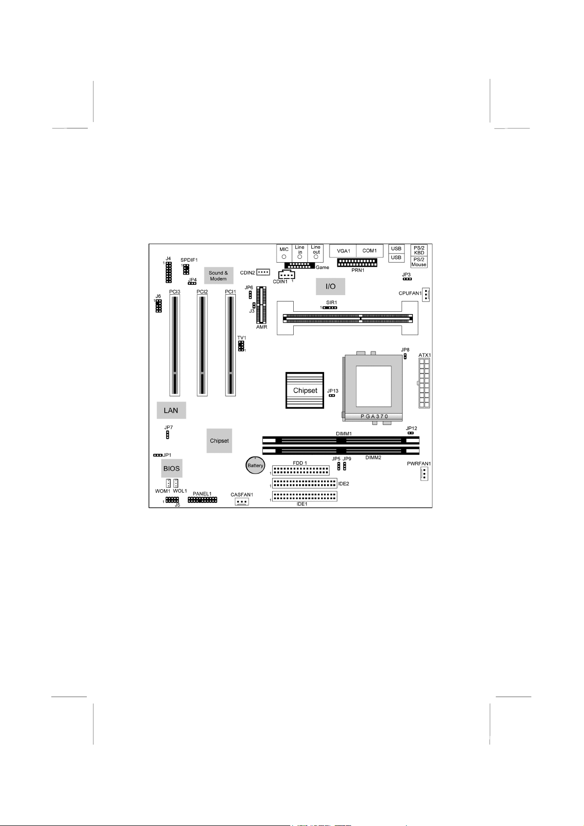
Mainboard Components
Use the diagram below to identify the major components on your
mainboard.
Note: Any jumpers on your mainboard that do not appear in
this illustration are for testing only.
Page 14
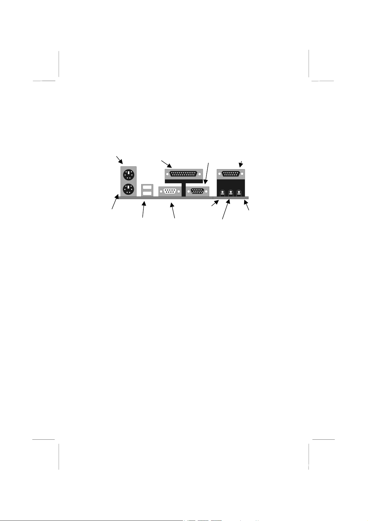
I/O Ports
The illustration below shows a side view of the I/O ports installed
on the mainboard.
PS/2 Mouse
Parallel Port LPT1
VGA Port
Game/MIDI Port
PS/2 Keyboard
USB Ports
Serial Port COM1/3
Stereo Out Jack
Stereo In Jack
Microphone Jack
Install the Processor
This mainboard has a Slot-1 which can be installed with Slot-1
processor cartridge including the Pentium-II, Pentium-III, and the
SEPP Celeron. It also has a Socket-370 which can be installed with
the PPGA Celeron or FCPGA Pentium III processor.
To ensure reliability, make sure that your PPGA/FCPGA
processor is fitted with a heatsink/cooling fan assembly.
You can install a Slot-1 processor or a Socket-370 processor. You
cannot install both a Slot-1 CPU and a Socket-370 CPU.
Take care that you do not try to install a Socket-7 processor into
the Socket-370. A Socket-7 processor such as the Pentium-MMX,
or the AMD K5/K6 does not fit in the socket-370.
Installing a Slot-1 Processor Cartridge
1. Locate Slot-1, and CPUFAN1 on the mainboard.
Page 15
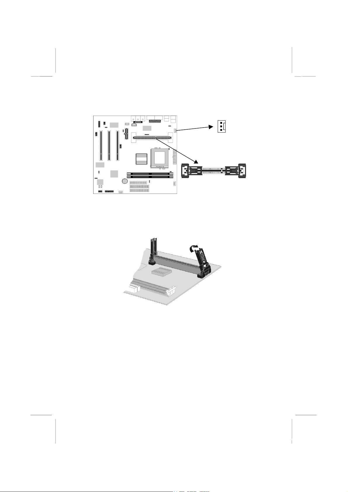
CPUFAN1
Slot-1 with pre-installed
cartridge holder. The
upright arms are folded
down for shipping.
2. The Slot-1 is installed with a cartridge holder. The upright
struts of the cartridge holder are folded down for shipping. Pull
the struts upwards so that they are in the upright position.
3. Insert the processor cartridge into the cartridge holder. Follow
the instructions given with your processor cartridge. The edge
connector on the cartridge has a notch so that it only fits into
the Slot-1 in the correct way.
4. Locate the cooling fan power supply CPUFAN1. Connect the
cable from the processor cartridge cooling fan to CPUFAN1.
5. On this mainboard, you can configure the processor by
entering the correct settings in the BIOS setup utility.
Page 16
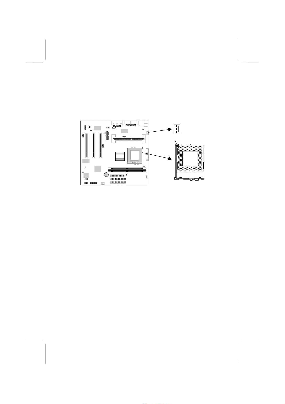
Installing a Socket-370 Processor
The processor installs into the ZIF (Zero Insertion Force) Socket370 on the mainboard.
1. Locate the Socket-370, and CPUFAN1. Pull the locking lever
out from the socket and swing it to the upright position.
Pin-1 Corner
CPUFAN1
Socket-370
2. On the processor, identify the pin-1 corner by noting that it has
a slight bevel.
3. On the Socket-370, identify the pin-1 corner. The pin-1 corner
is on the same side as the locking lever, closest to the top of the
lever when it is in the locked position.
4. Match the pin-1 corners and insert the processor into the
socket. No force is required and the processor should drop into
place freely.
5. Swing the locking lever down and hook it under the catch on
the side of the socket. This locks the processor in the socket.
6. If the processor is installed with a cooling fan assembly,
connect the cable from the fan to the CPU fan power connector
CPUFAN1.
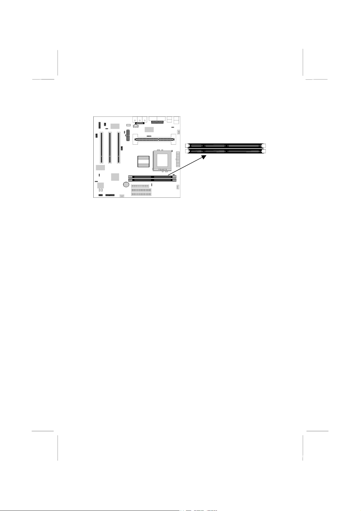
Install Memory
The mainboard has two DIMM slots which can be installed with
memory modules. You must install at least one memory module in
order to use the mainboard.
Page 17
DIMM1
DIMM2
For this mainboard, you must use 168-pin, 3.3V memory modules
installed with SDRAM memory chips. You must use memory that
operates on a 100 MHz memory bus (PC-100 memory). You can
install any size of memory module from 16 MB up to 256 MB, so
the maximum memory size is 2 x 256 MB = 512 MB.
The edge connectors on the memory modules have cut outs, which
coincide with struts in the DIMM slots, so the memory modules
can only be installed in the correct way.
On the DIMM slot, pull the locking latches at either end of the
slots outwards. Position the memory module correctly and insert it
into the DIMM slot. Press the module down into the slot so that the
locking latches lever inwards and lock the module in place.
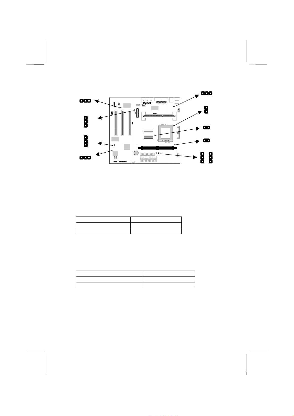
Set the Jumpers
Jumpers are sets of pins that can be connected together with
jumper caps. The jumper caps change the way the mainboard
operates by changing the electronic circuits on the mainboard. If a
jumper cap connects two pins, we say the pins are SHORT. If a
jumper cap is removed from two pins, the pins are OPEN.
Page 18
JP8
JP4
1
1
1
JP7
1
1
JP1
1
Jumper JP1: Clear CMOS Memory
Use this jumper to clear the contents of the CMOS memory. You
may need to clear the CMOS memory if the settings in the setup
utility are incorrect and prevent your mainboard from operating. To
clear the CMOS memory, disconnect all the power cables from the
mainboard and then move the jumper cap into the CLEAR setting
for a few seconds.
Function Jumper Setting
Normal Operation Short Pins 1-2
Clear CMOS Memory Short Pins 2-3
Jumper JP3: Keyboard Power On Selector
You can use hot keys on your keyboard as a power on/off switch
for the system. Use this jumper to turn this feature on or off.
Note: Make sure that the system can provide 1A on +5VSB (+5V
Standby) signal before using the Keyboard Power On function.
Function Jumper Setting
Enable Keyboard Power On Short Pins 1-2
Disable Keyboard Power On Short Pins 2-3
Page 19

Jumper JP4: Onboard Audio Enable/Disable
Use this jumper to enable or disable the onboard audio system and
modem. Disable the built-in audio if you plan on using another
audio system on an expansion card.
Function Jumper Setting
Enable Audio/Modem Short Pins 1-2
Disable Audio/Modem Short Pins 2-3
Jumper JP5: System Bus Frequency (100 MHz) Selector
Use this jumper to set the system bus frequency. In the normal
setting, the system automatically selects the correct frequency
according to the kind of processor installed. In the Force 100 MHz
setting, the system uses a 100 MHz system bus even if the
processor is designed to operate with a 66 MHz bus.
Function Jumper Setting
Normal Short Pins 1-2
Force 100 MHz Short Pins 2-3
Jumper JP6: Audio Codec Selector
Use this jumper to select if the system uses the audio codec chip
integrated on the mainboard, or an audio codec chip located on an
optional AMR card.
Function Jumper Setting
Turn on onboard codec Short Pins 1-2
Turn off onboard codec Short Pins 2-3
Jumper JP7: Enable/Disable Onboard LAN
Use this 3-pin jumper to enable or disable the onboard network
adapter.
Function Jumper Setting
Enable Onboard LAN Short Pins 1-2
Disable Onboard LAN Short Pins 2-3
Jumper JP8: IDT or Intel processor Selector
Use this 2-pin jumper to select if you are installing an Intel
processor or an IDT processor in the socket-370 processor socket.
Function Jumper Setting
Intel processor Short Pins 1-2
IDT processor Open Pins 1-2
Page 20

Jumper JP9: System Bus Frequency (133 MHz) Selector
(only for i810e chipset)
Use this jumper to set the system bus frequency. In the normal
setting, the system automatically selects the correct frequency
according to the kind of processor installed. In the Force 133 MHz
setting (only for i810e chipset), the system uses a 133 MHz system
bus even if the processor is designed to operate with a 100 MHz
bus.
Function Jumper Setting
Normal Short Pins 1-2
Force 133 MHz Short Pins 2-3
Jumper JP12, JP13: Normal/Flexible setting for socket370
Use these two jumpers to set the socket-370 to the normal setting
or the flexible setting. Some future high-performance socket-370
processors require the flexible setting.
Function JP12 Setting JP13 Setting
Normal Open Pins 1-2 Open Pins 1-2
Flexible PGA-370 Short Pins 1-2 Short Pins 1-2
Page 21
J3
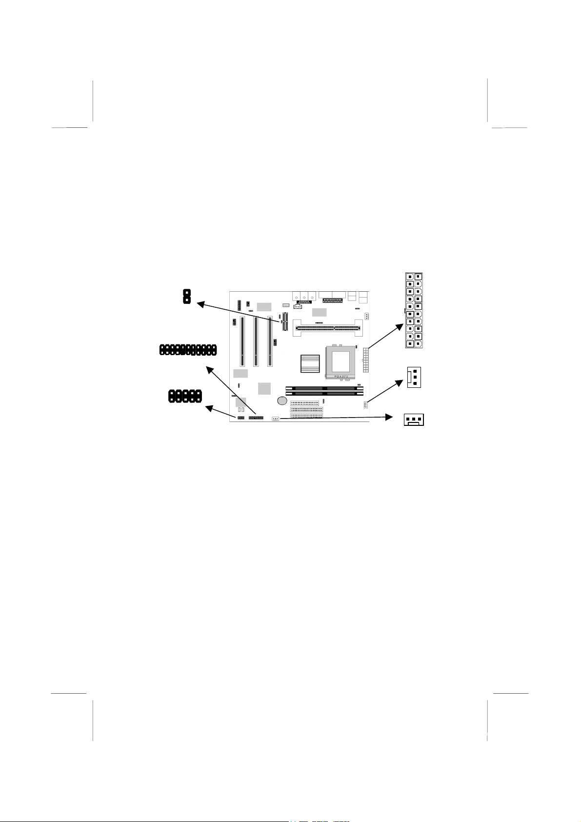
Install the Mainboard
Install the mainboard into the system chassis. This mainboard uses
the mini-ATX format with a twin-tier I/O ports. Ensure that your
case has an I/O template that can be used by this mainboard.
Install the mainboard into the unit case. Follow the instructions
provided by the case manufacturer using the screws and mounting
points provided in the chassis.
1
Connect the power cable from the ATX power supply unit to the
power connector ATX1 on the mainboard.
If the case that you are using has chassis and/or system power
supply cooling fan, connect the cable from the fan to the onboard
chassis/system power supply cooling fan power CASFAN1/
PWRFAN1.
If the case has a case open detect alarm, connect the cable to the
case open detect circuit J3.
If the case has extra USB ports, you can connect them to J5.
Then connect the case switches and indicator LEDs to the bank of
switch and LED connectors PANEL1. See the illustration below
for a guide to the pin functions of the PANEL1 case connector.
PWRFAN1
Page 22
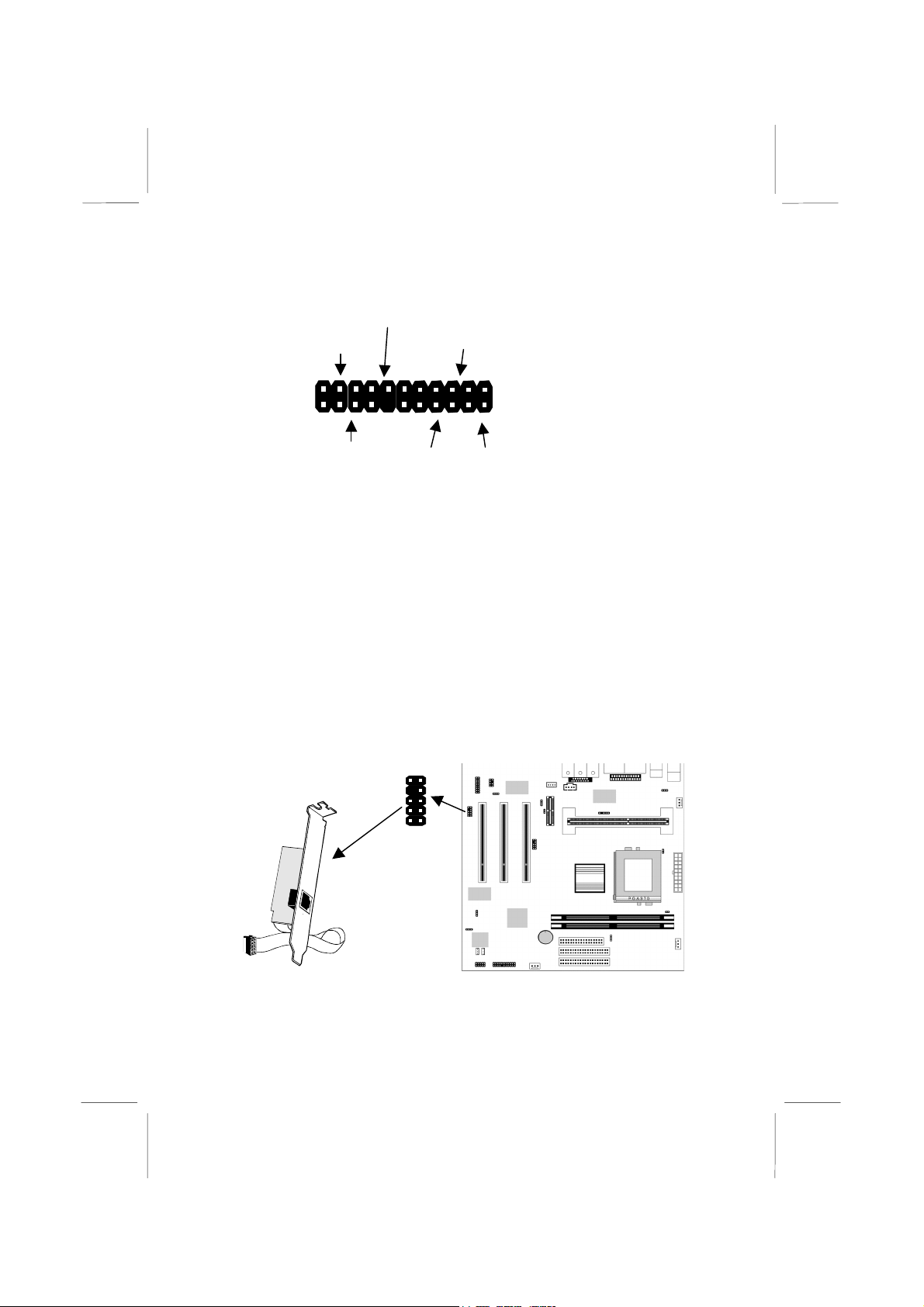
Power LED
Pins 2-4-6
Keylock
Pins 8-10
SMI Button Pins 19-20
Reset Switch
Pins 17-18
2
1
22
21
Speaker
Pins 1-3-5-7
HDD LED
Pins 15-16
Power Button/Suspend
Switch Pins 21-22
Install the Extension Brackets
The extension brackets are used to transmit features on the
mainboard to external connectors that can be fixed to the system
chassis. Follow the steps below to install the extension brackets.
Note: All the ribbon cables used on the extension brackets carry a
red stripe on the pin-1 side of the cable.
LAN Adapter Extension Bracket
This bracket supports an RJ45 network connector and connects to
the built in J6 LAN header on the mainboard.
1. On the mainboard, locate the J6 LAN header for this bracket.
2. Plug the cable from the bracket into the LAN header.
1
J6 LAN Header
LAN Extension
Bracket
Page 23
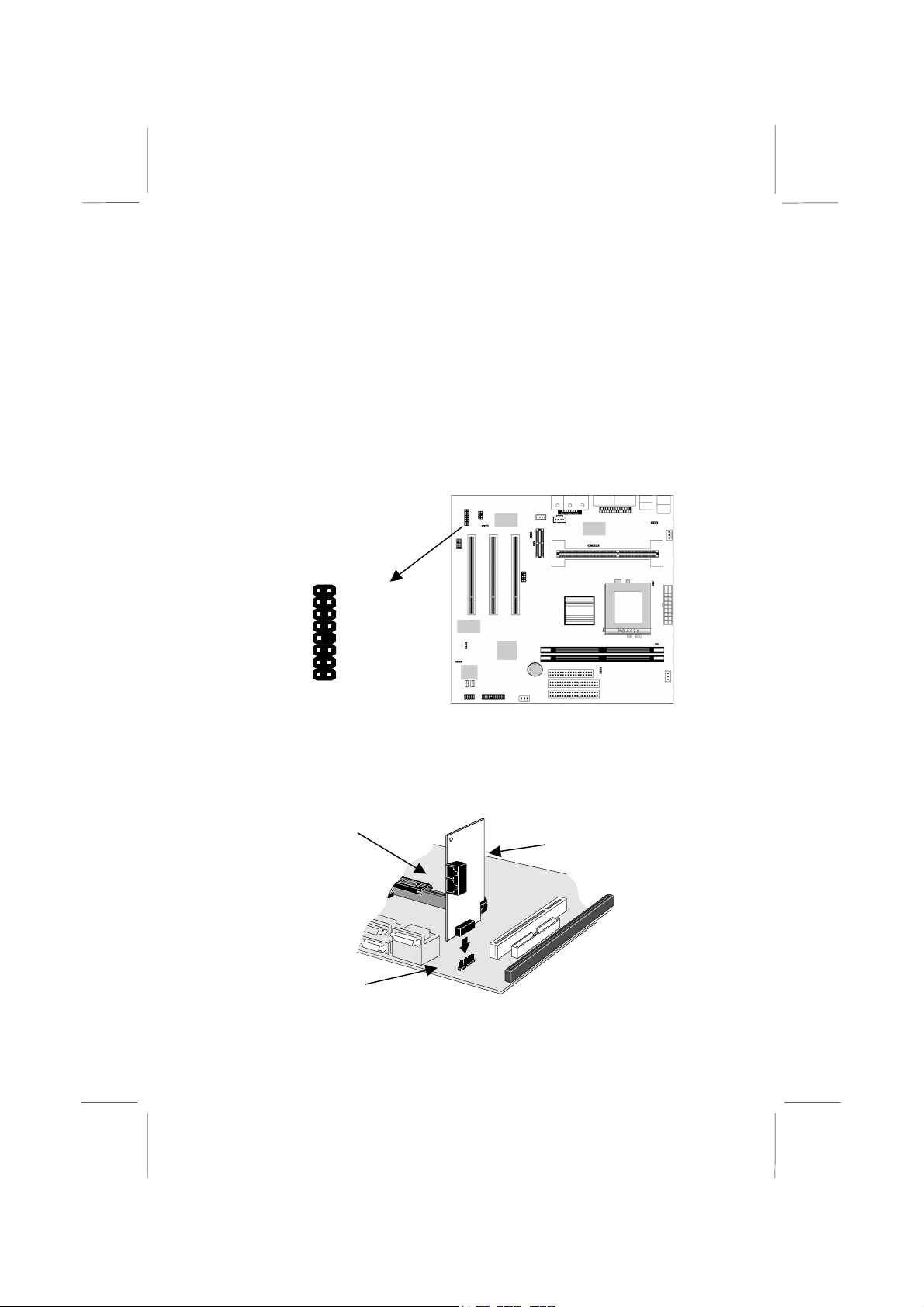
3. In the system chassis, remove a blanking plate from one of the
expansion slots and install the extension bracket in the slot.
Use the screw that held the blanking plate in place to secure
the extension bracket.
Fax/Modem DAA Module
The Fax/Modem DAA module plugs directly into the mainboard
adjacent to an expansion slot in the system chassis. When you
remove the blanking plate from the system chassis, you can access
the LINE and TEL RJ11 connectors on the metal edge of the
Fax/Modem DAA module.
J4-MODEM Header
AUX 5V 13
GND 1
GND 3
GND 5
AUX 3V 7
HOOK 9
RIN 11
MUTE 15
2 MCLK
4 FRA-SY
6 SCLK
8 RIN-WAK
10 GPIO
12 SDO
14 SDI
16 RST
1. Locate the J4 Modem header on the mainboard.
2. Plug the Fax/Modem DAA module into the J4 Modem header.
3. Remove the blanking plate adjacent to the Fax/Modem DAA
module.
Line & Tel
RJ11 Sockets
Modem DAA Module
J4 Modem Header
Page 24
Optional Extension Brackets
For this mainboard, you can also obtain an Optic Module extension
bracket and an AV/S-Video output extension bracket. Install these
brackets by following the steps below.
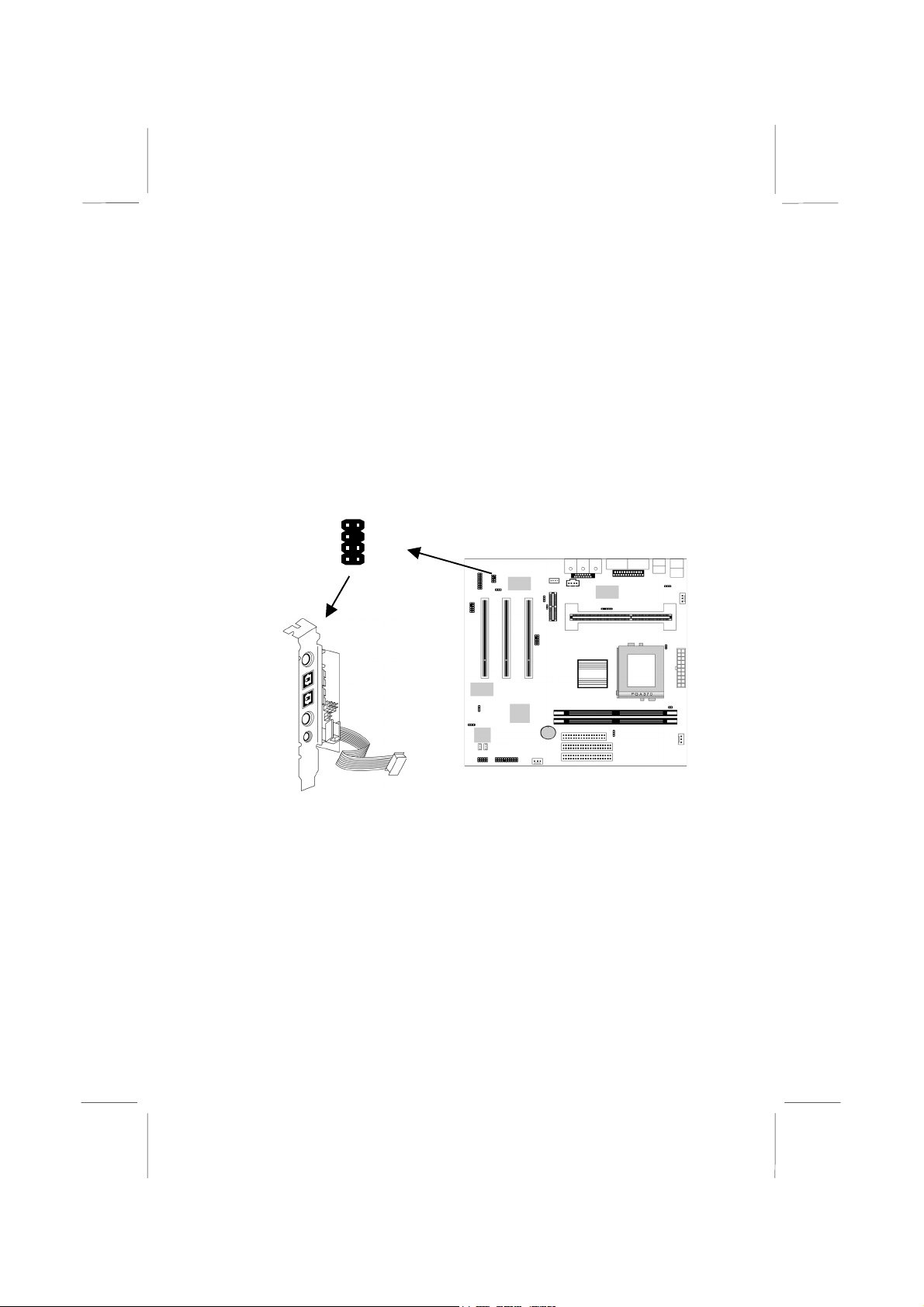
Optic Module Extension Bracket
This bracket has two RCA jacks for digital audio in/out, and an
auxiliary jack for a Stereo Line-in device. It also provides a pair of
optic fiber interface which enables the communication with
MiniDisk or high-end audio systems.
SPDIF Out
1. On the mainboard, locate the SPDIF1 header for this bracket.
2. Plug the cable from the bracket into the SPDIF1 header.
3. In the system chassis, remove a blanking plate from one of the
Internal Digital Audio
If you have an optional internal digital audio cable, you can also
use it to connect the digital audio output connector of a CD-ROM
or DVD drive to the pins 5-6 of SPDIF1.
Optic Out
Optic In
SPDIF In
Aux In
Aux I n(L) 1
+12V 3
SPDIF/In 5
SPDIF/Out 7
2 Aux In(R)
6 GND
8 GND
SPDIF1 Header
Digital Audio
Extension Bracket
expansion slots and install the extension bracket in the slot.
Use the screw that held the blanking plate in place to secure
the extension bracket.
Page 25
A
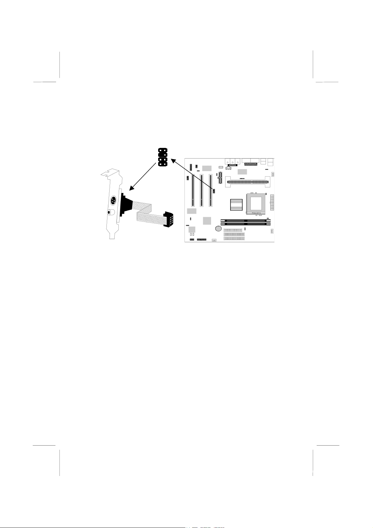
AV/S-Video Output Extension Bracket
This bracket has an AV jack and a S-Video jack for the television
out.
TV1 Header
1
V/S-Video Output
Extension Bracket
1. On the mainboard, locate the TV1 header for this bracket.
2. Plug the cable from the bracket into the TV1 header.
3. In the system chassis, remove a blanking plate from one of the
expansion slots and install the extension bracket in the slot.
Use the screw that held the blanking plate in place to secure
the extension bracket.
Page 26
Install Other Devices
Install and connect any other devices in the system following the
steps below.
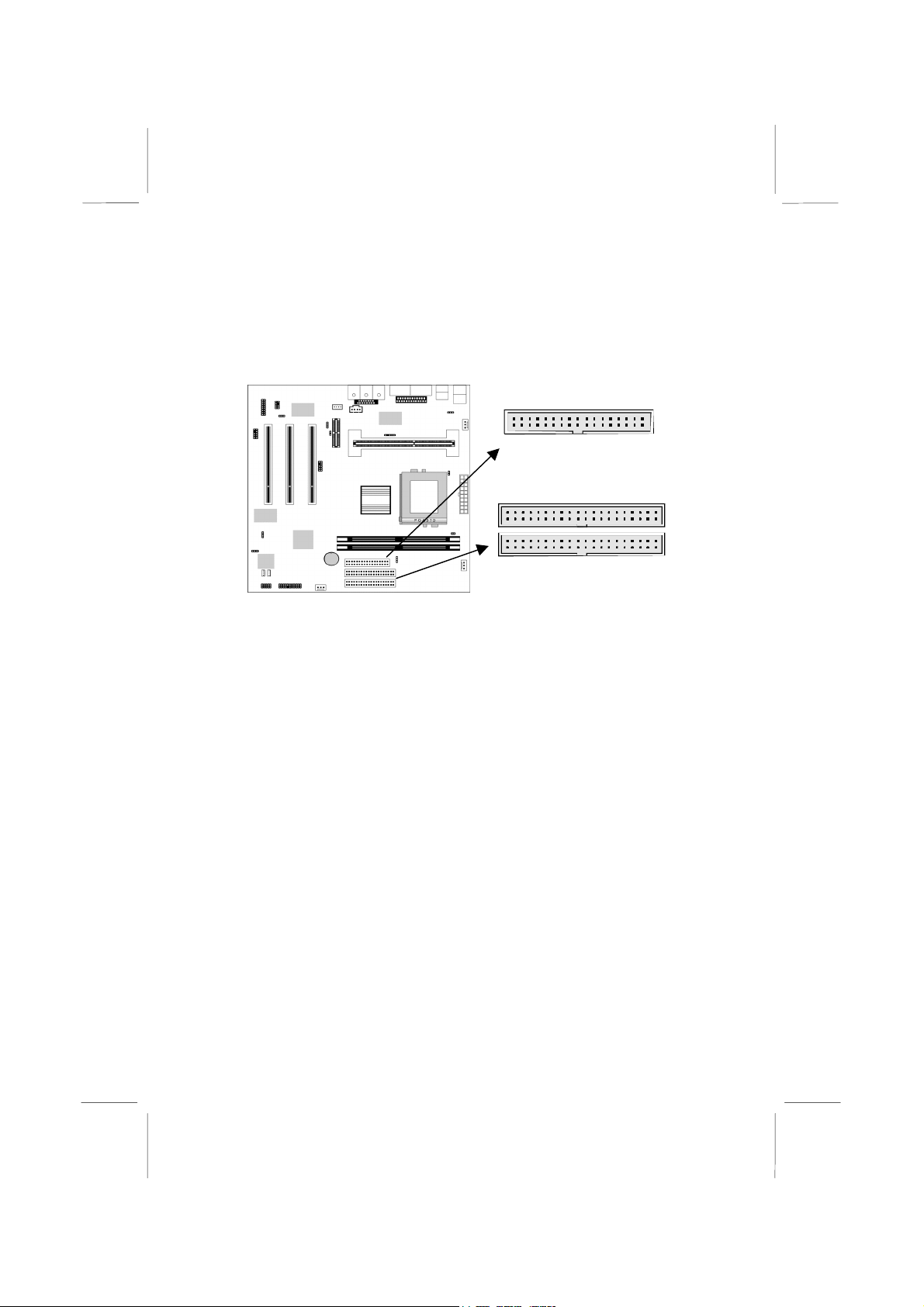
Floppy Disk Drive
The mainboard ships with a floppy disk drive cable that can
support one or two drives. Drives can be 3.5” or 5.25” wide, with
capacities of 360K, 720K, 1.2MB, 1.44MB, or 2.88MB.
Install your drives and supply power from the system power unit.
Use the cable provided to connect the drives to the floppy disk
drive header FDD1.
IDE Devices
IDE devices include hard disk drives, high-density diskette drives,
and CD-ROM/DVD drives.
The mainboard ships with an IDE cable that can support one or two
IDE devices. If you connect two devices to a single cable, you
must configure one of the drives as Master and one of the drives as
Slave. The documentation of the IDE device will tell you how to
configure for Master or Slave.
Install the device(s) and supply power from the system power unit.
Use the cable provided to connect the device(s) to the Primary IDE
channel connector IDE1 on the mainboard.
1
1
1
FDD1
IDE2
IDE1
Page 27
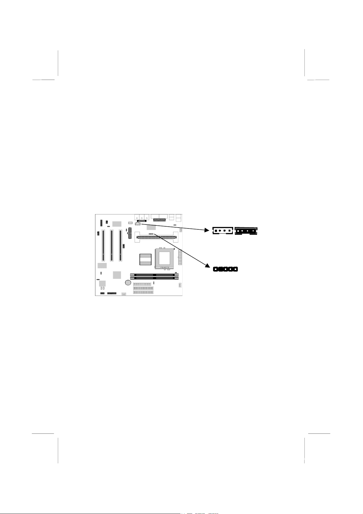
If you want to install more IDE devices, you can purchase a second
IDE cable and connect one or two devices to the Secondary IDE
channel connector IDE2 on the mainboard. If you have two devices
on the cable, one must be Master and one must be Slave.
Internal Sound Connections
If you have installed a CD-ROM drive or a DVD drive, you can
connect the sound output of the drive to the built-in sound system.
On the mainboard, locate the two 4-pin connectors for CDIN1 and
CDIN2. There are two kinds of connector because different brands
of CD-ROM drive have different kinds of cable connectors on their
audio output cable. Connect the cable to the appropriate connector.
1
CDIN2 CDIN1
SIR1-Infrared
Header
1
Infrared Port
You can install the mainboard with an optional infrared port. You
can purchase these options from third-party vendors.
1. On the mainboard locate the infrared port header SIR1.
2. Connect the cable from the infrared port to the infrared header
SIR1 and then secure the infrared port to an appropriate place
in the system chassis.
Expansion Slots
This mainboard has three 32-bit PCI expansion slots and one AMR
slot. The PCI1 slot is shared with the onboard VGA and the
onboard Modem, and the PCI3 slot is shared with the onboard
Page 28
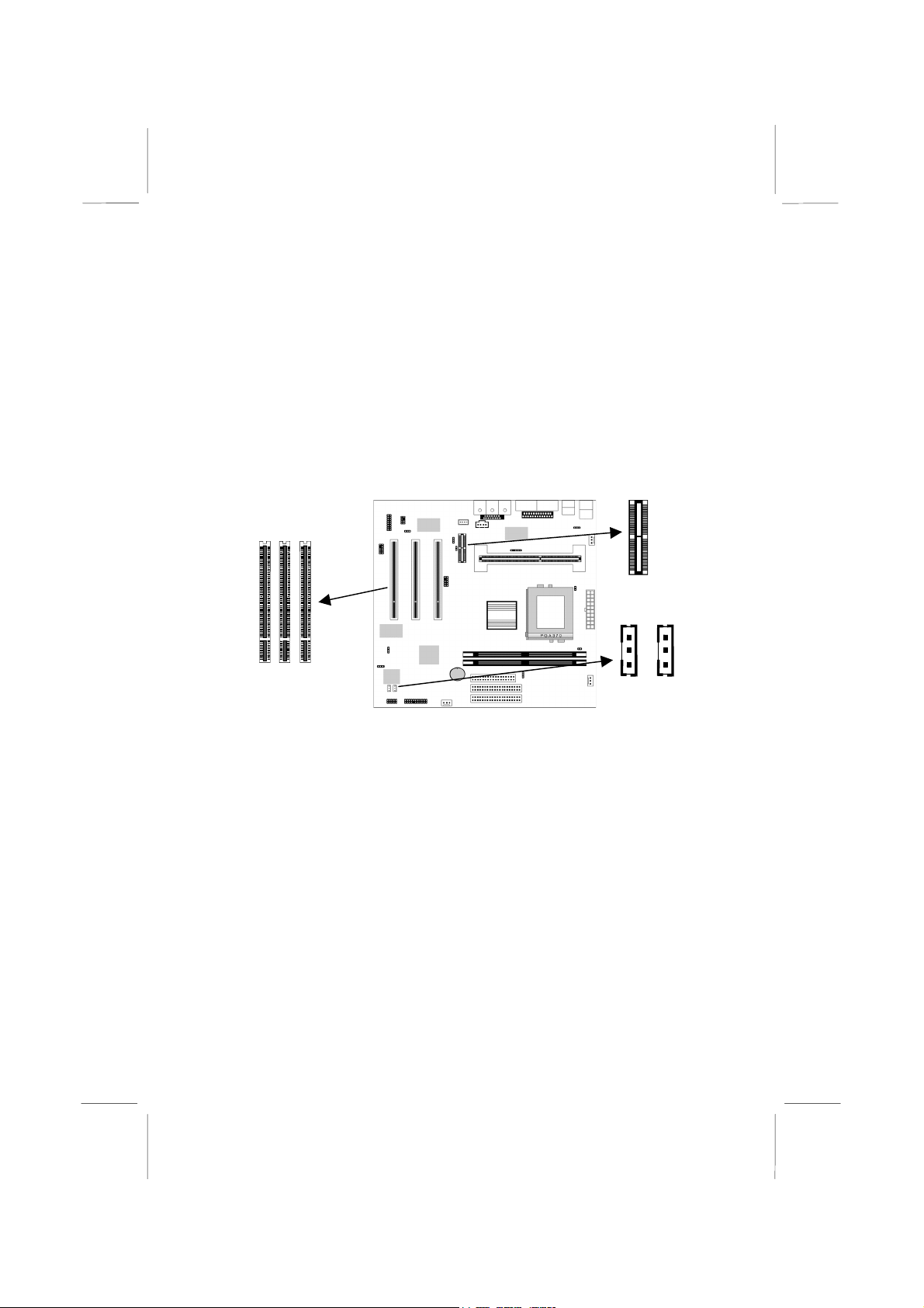
LAN. It means that you can use either one of shared both but you
cannot use the both at the same time.
AMR Slot
The AMR (Audio Modem Riser) slot is an industry standard slot
that allows for the installation of a special audio/modem riser card.
Different territories have different regulations regarding the
specifications of a modem card. You can purchase an AMR card
that is approved in your area and install it directly into the AMR
slot.
PCI3 PCI2 PCI1
AMR
WOM1
Header
WOL1
Heade
Follow the steps below to install a PCI/AMR expansion card.
1. Locate the PCI or AMR slot on the mainboard.
2. Remove the blanking plate from the appropriate expansion slot
on the system chassis.
3. Install the edge connector of the expansion card into the slot
and press it quite firmly down so that it is seated correctly.
4. Secure the bracket of the card into the expansion slot in the
system chassis using the screw that held the blanking plate in
place.
Note: If you have installed an AMR card, you should check the
settings of jumpers JP4 (audio/modem enable/disable) and JP6
(select onboard codec or AMR codec). You should disable the
onboard audio/modem to avoid conflicts with the AMR card. You
can use the AMR codec chip (if it has one) or the onboard codec
chip.
Page 29

Wake On LAN
If you have installed a LAN adapter card, connect the card to the
wake on LAN header WOL1. This allows incoming traffic to
resume the system from a software power down.
Wake On Modem
If you have installed a fax/modem card, connect the fax/modem to
the wake on modem connector WOM1. You can then use the setup
utility to program your computer to resume from a power saving
mode whenever there is an incoming call to the fax/modem.
Page 30

Chapter 3
BIOS Setup
Introduction
The BIOS setup utility stores information about your computer
such as the date and time, the kind of hardware you have installed,
and so on. Your computer uses this information to initialize all the
components at boot up time, and make sure that everything runs
smoothly.
If the information in the setup utility is incorrect, it may cause your
system to malfunction. It can even stop your computer from
booting properly. If this happens, you can use the clear CMOS
jumper to clear the CMOS memory area that is used to store the
setup information, or you can hold down the End key while you
reboot your computer, Holding down the End key also clears the
setup information.
You can run the setup utility and manually make changes to the
setup utility. You might need to do this to configure some of the
hardware that you add to the mainboard, such as the CPU, the
memory, disk drive, etc.
Page 31
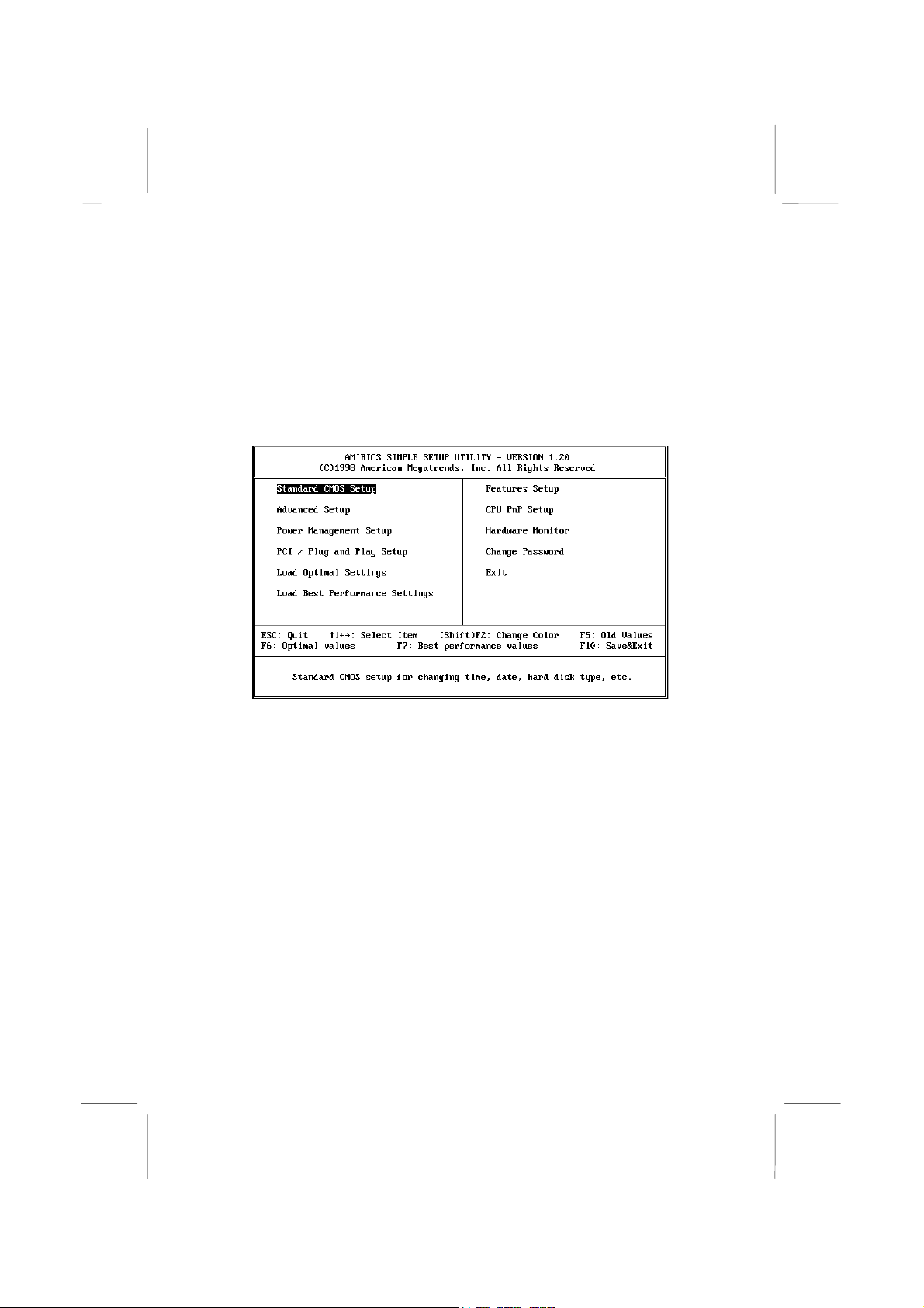
Running the Setup Utility
Each time your computer starts, before the operating system is
booted, a message appears on the screen that prompts “Hit <DEL>
if you want to run SETUP”. When you see this message, press the
Delete key and the Mainmenu page of the setup utility appears on
your monitor.
You can use the cursor arrow keys to highlight any of the options
on the Mainmenu page. Press Enter to select the highlighted
option. To leave the setup utility, press the Escape key. Hold down
the Shift key and press F2 to cycle through the optional color
schemes of the setup utility.
Some of the options on the Mainmenu page lead to tables of items
with installed values. In these pages, use the cursor arrow keys to
highlight the items, and then use the PgUp and PgDn keys to cycle
through the alternate values for each of the items. Other options on
the Mainmenu page lead to dialog boxes which require you to
answer Yes or No by hitting the Y or N keys.
If you have already made changes to the setup utility, press F10 to
save those changes and exit the utility. Press F5 to reset the
changes to the original values. Press F6 to install the setup utility
Page 32
with a set of default values. Press F7 to install the setup utility with
a set of best-performance values.
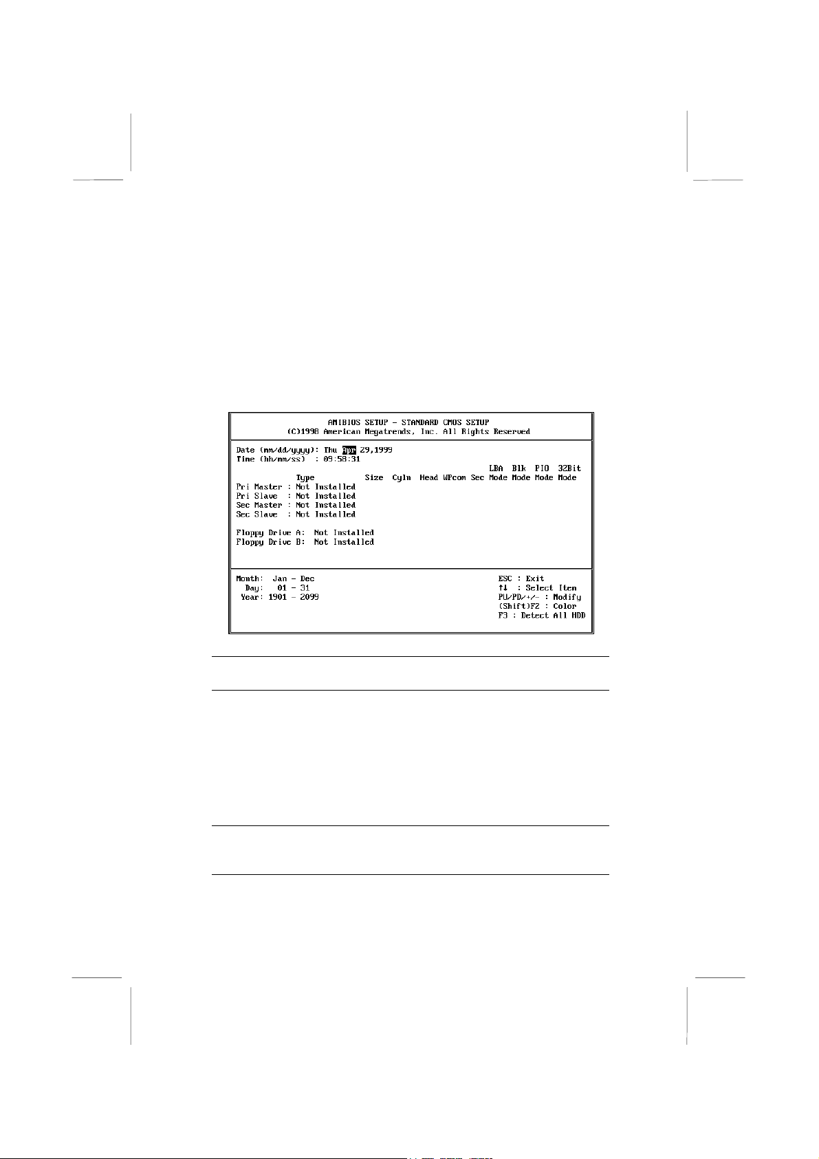
Standard CMOS Setup Page
Use this page to set basic information such as the date and time, the
IDE devices, and the diskette drives. If you press the F3 key, the
system will automatically detect and configure the hard disks on
the IDE channels.
Date & Time
Pri Master
Pri Slave
Sec Master
Sec Slave
Floppy Drive A
Floppy Drive B
Use these items to install your system with the
correct date and time
Use these items to configure devices on the
primary and secondary IDE channels. To
configure a hard disk drive, choose
setting fails to find a hard disk drive, set it to
Auto
, and then fill in the hard disk characteristics
User
(Size, Cyls, etc.) manually. If you have a CDROM drive, select the setting
have an ATAPI device with removable media
(e.g. a ZIP drive or an LS-120) select
Use these items to set the size and capacity of
the floppy diskette drive(s) installed in the
system.
CDROM
Auto
. If you
ARMD
. If the
.
Page 33

Advanced Setup Page
Use this page to set more advanced information about your system.
Take some care with this page. Making changes can affect the
operation of your computer.
AMIBIOS SETUP – ADVANCED SETUP
Trend ChipAwayVirus Enabled
st
Boot Device IDE-0
1
nd
Boot Device Floppy
2
Try Other Boot Devices Yes
S.M.A.R.T. for Hard Disks Disabled
BootUp Num-Lock On
Floppy Drive Swap Disabled
Floppy Drive Seek Disabled
Primary Display VGA/EGA
Password Check Setup
Boot to OS/2 Over 64MB No
Internal Cache Enabled
System BIOS Cacheable Disabled
Video BIOS Shadow Enabled
DRAM Page Closing Policy Open
CAS Latency 3 SCLKs ESC : Quit
Graphic Win Size 64M F1 : Help PU/PD/+/- : Modify
Delayed Transaction Disabled F5 : Old Values (Shift)F2 : Color
F6 : Load Optimal values
F7 : Load Best performance values
Trend ChipAway
Virus
1st Boot Device
nd
2
Boot Device
Try Other Boot
Devices
S.M.A.R.T. for
Hard Disks
BootUp NumLock
©1998 American Megatrends, Inc. All Rights Reserved
: Select Item
This mainboard has built-in virus protection in the
firmware. Use this item to enable or disable the
built-in virus protection.
Use these two items to determine the order and
priority that your computer follows to load an
operating system at start-up time.
If you enable this item, the system will also
search for other boot devices if it fails to find an
operating system from the first two locations.
Enable this item if your hard disk(s) supports
SMART (Self-Monitoring, Analysis and Reporting
Technology).
This items determines if the Num Lock key is
active or inactive at system start-up time.
Page 34

Floppy Drive
Swap
Floppy Drive
Seek
Primary Display
Password Check
Boot to OS/2
Over 64MB
Internal Cache
System BIOS
Cacheable
Video BIOS
Shadow
DRAM Page
Closing Policy
CAS Latency
Graphic Win Size
Delayed
Transaction
If you have two diskette drives installed and you
enable this item, drive A becomes drive B and
drive B becomes drive A.
If you enable this item, your system will check the
diskette drives at start up time. Disable this item
unless you are using an old 360K diskette drive.
Use this item to determine the display devices for
the primary display of your computer.
If you have installed a password on your system,
use this item to determine if the password is
required to enter the setup utility (
required at start-up time and to enter the setup
utility (
Enable this item if you are booting the OS/2
operating system and you have more than 64MB
of memory installed.
Leave this item enabled since all the processors
that can be installed on this board have internal
cache memory.
If you enable this item, a segment of the system
BIOS will be cached to main memory for faster
execution.
When this item is enabled, 32 kilobytes of the
system video BIOS is copied to system memory
from where it can execute more rapidly.
This item determines the operation of the
memory Page Closing Policy. We recommend
that you leave this item at the default value.
This item determines the operation of the main
memory CAS (column address strobe). We
recommend that you leave this item at the default
value.
This item determines the operation of the
onboard graphics adapter. We recommend that
you leave this item at the default value.
If you enable this item, your system will delay the
transaction mechanism for AGP master/PCI
master. We recommend that you leave this item
at the default value.
Always
).
Setup
) or
Page 35
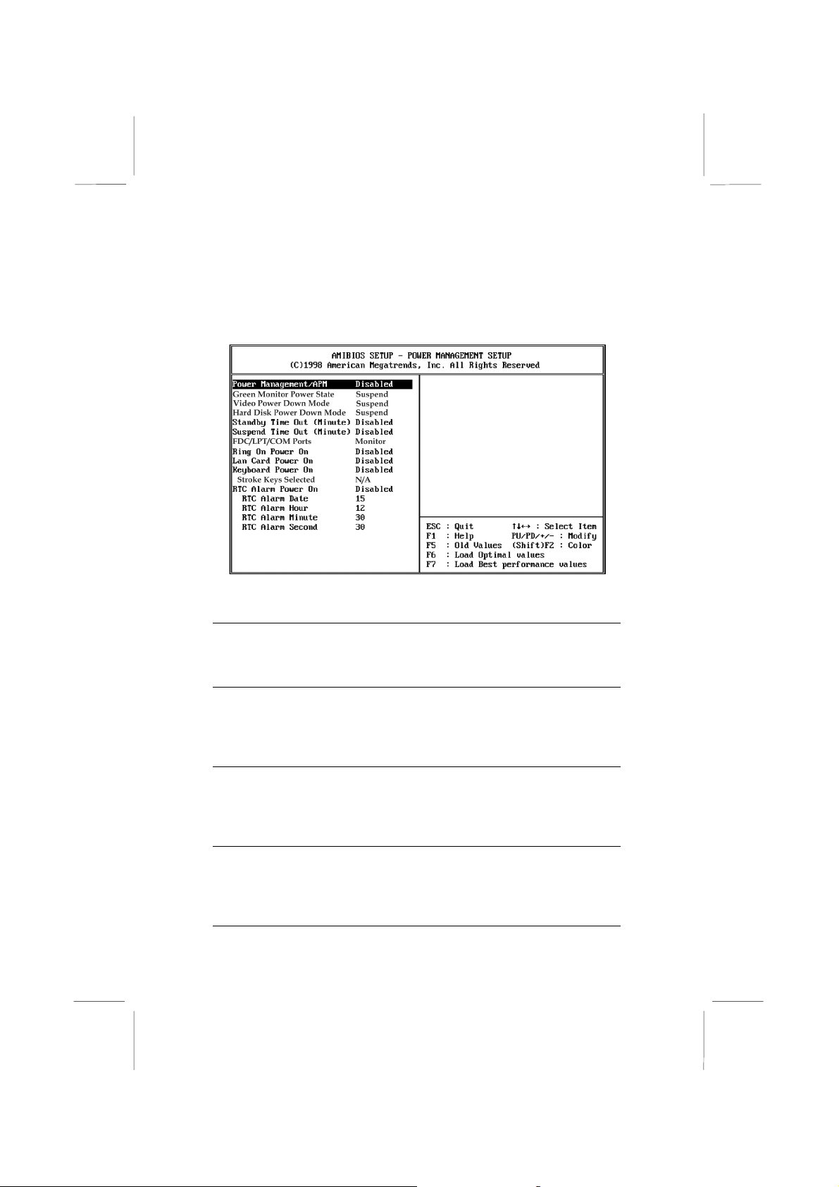
Power Management Setup Page
This page sets some of the parameters for the system power
management operation.
Power
Management/APM
Green Monitor
Power State
Video Power Down
Mode
Hard Disk Power
Down Mode
Use this item to enable or disable the power
management routines. If you enable the power
management, you can use the items below to
set the power management operation.
Use this item to determine which power-saving
mode is required to power down a green PCcompliant monitor. You can force the monitor to
power down in Standby or Suspend modes, or
you can disable the powerdown.
Use this item to determine which power-saving
mode is required to power down the graphics
sub-system. You can force the graphics to
power down in Standby or Suspend modes, or
you can disable the powerdown.
Use this item to determine which power-saving
mode is required to power down the hard disk
drive(s). You can force the hard disk to power
down in Standby or Suspend modes, or you
can disable the powerdown.
Page 36

Standby Time Out
(Minute)
Suspend Time Out
(Minute)
FDC/LPT/COM
Ports
Ring On Power On
Lan Card Power
On
Keyboard Power
On
Stroke Keys
Selected
RTC Alarm Power
On
This sets the timeout for standby mode in
minutes. If the time selected passes without any
system activity, the computer will enter the
power-saving standby mode.
This sets the timeout for suspend mode in
minutes. If the time selected passes without any
system activity, the computer will enter the
power-saving suspend mode.
If you set this item to Monitor, any activity on
the floppy disk drive(s)/the parallel port/the
serial port can resume the system from a power
saving mode.
Your system can enter a software power down.
If you enable this item, the system can
automatically resume if there is an incoming call
on the built-in Fax/Modem.
Your system can enter a software power down.
If you enable this item, the system can
automatically resume if there is traffic on the
network adapter.
Your system can enter a software power down.
If you enable this item, you can resume the
system by pressing hot keys on the keyboard.
You must enable the jumper for Keyboard
Power On.
If you have enabled the Keyboard Power On,
use this item to select the hot keys to power on
the system.
Your system can enter a software power down.
If you enable this item, the system can
automatically resume at a fixed time on the
system’s RTC (realtime clock). Use the items
below to set the date and time of the wake-up
alarm.
PCI / Plug and Play Setup Page
This page sets some of the parameters for devices installed on the
system PCI bus, and devices that use the system plug and play
capability.
Page 37

AMIBIOS SETUP – PCI / PLUG AND PLAY SETUP
©1998 American Megatrends, Inc. All Rights Reserved
Plug and Play Aware O/S Yes
Primary Graphics Adapter OnBoard VGA
Assign IRQ for VGA Yes
ESC : Quit
F1 : Help PU/PD/+/- : Modify
F5 : Old Values (Shift)F2 : Color
F6 : Load Optimal values
F7 : Load Best performance values
: Select Item
Plug and Play
Aware O/S
Primary Graphics
Adapter
Assign IRQ for
VGA
Enable this item if you are using an O/S that
supports Plug and Play such as Windows 95 or
98.
Use this item to define if your primary graphics
adapter is installed in a onboard VGA or add-on
VGA.
If this item is enabled, an IRQ will be assigned
to the VGA graphics system.
Load Optimal Settings
If you select this item and press Enter a dialog box appears. If you
press Y, and then Enter, the setup utility is loaded with a set of
optimal default values. The optimal default values are not very
demanding and they should allow your system to function with
most kinds of hardware and memory chips.
Load Best Performance Settings
If you select this item and press Enter a dialog box appears. If you
press Y, and then Enter, the setup utility is loaded with a set of
best-performance default values. The optimal default values are
quite demanding and your system might not function properly if
Page 38
you are using slower memory chips or other kinds of lowperformance components.
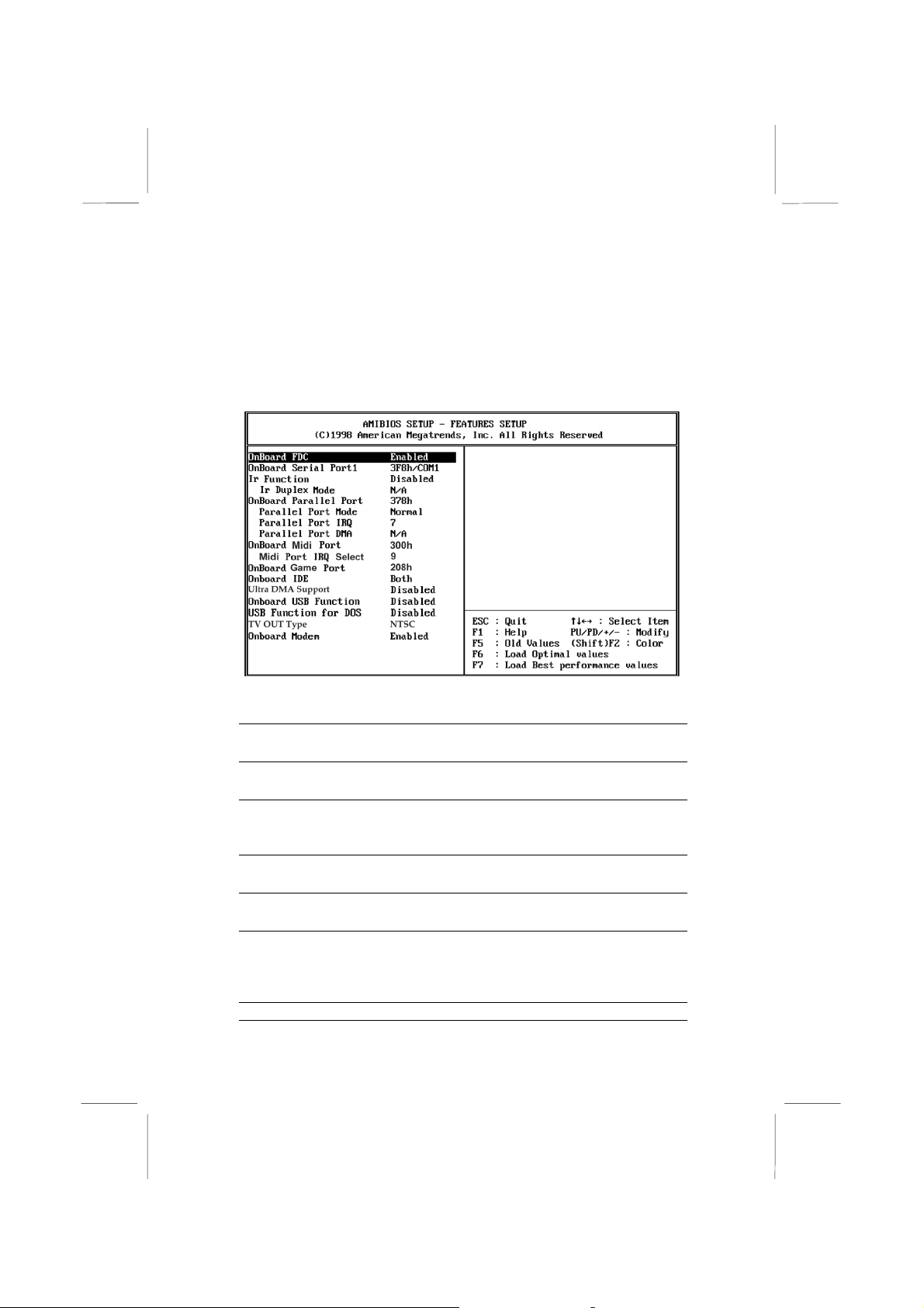
Features Setup Page
This page sets some of the parameters for peripheral devices
installed on the system.
Onboard FDC
Onboard Serial
Port1
IR Function
IR Duplex Mode
Onboard Parallel
Port
Parallel Port Mode
Parallel Port IRQ
Use this item to enable or disable the onboard
floppy disk drive interface.
Use this item to enable or disable the onboard
serial port COM1, and to assign a port address
Use this item to define the protocol for an
infrared port if you have installed an optional IR
port.
Use this item to define if the optional infrared
port is full-duplex or half-duplex.
Use this item to enable or disable the onboard
parallel port LPT1, and to assign a port address
Use this item to determine the parallel port
mode. You can select Normal, ECP (Extended
Capabilities Port), EPP (Enhanced Parallel
Port), or ECP + EPP.
Use this item to assign an IRQ to the parallel
Page 39

Parallel Port DMA
Onboard Midi Port
Midi Port IRQ
Onboard Game
Port
Onboard IDE
Ultra DMA Support
OnBoard USB
Function
USB Function for
DOS
TV Out Type
Onboard Modem
port.
Use this item to assign a DMA channel to the
parallel port.
Use this item to enable or disable the onboard
MIDI port, and to assign a port address
Use this item to assign an IRQ to the MIDI port.
Use this item to enable or disable the onboard
Game port, and to assign a port address
Use this item to enable or disable either of the
two onboard IDE channels, Primary or
Secondary.
Use this item to enable or disable the Ultra
DMA function to support the IDE devices.
Use this item to enable or disable the USB
(Universal Bus Ports) that are integrated on this
mainboard.
If you have enabled the USB function, use this
item to enable or disable USB when you are
working in the DOS environment.
This item is available when TV out kit onboard
(optional). Use this item to determine the type
of the TV Out . You can select NTSC or PAL.
Use this item to enable or disable the onboard
Modem device
Page 40

CPU PnP Setup Page
This page lets you configure the mainboard for the kind of CPU
that you have installed.
AMIBIOS SETUP – CPU PnP SETUP
©1998 American Megatrends, Inc. All Rights Reserved
CPU Speed (MHz) 400 (66x6)
ESC : Quit
F1 : Help PU/PD/+/- : Modify
F5 : Old Values (Shift)F2 : Color
F6 : Load Optimal values
F7 : Load Best performance values
CPU Speed
Use this item to define the clock speed of the
processor that you have installed.
: Select Item
Page 41
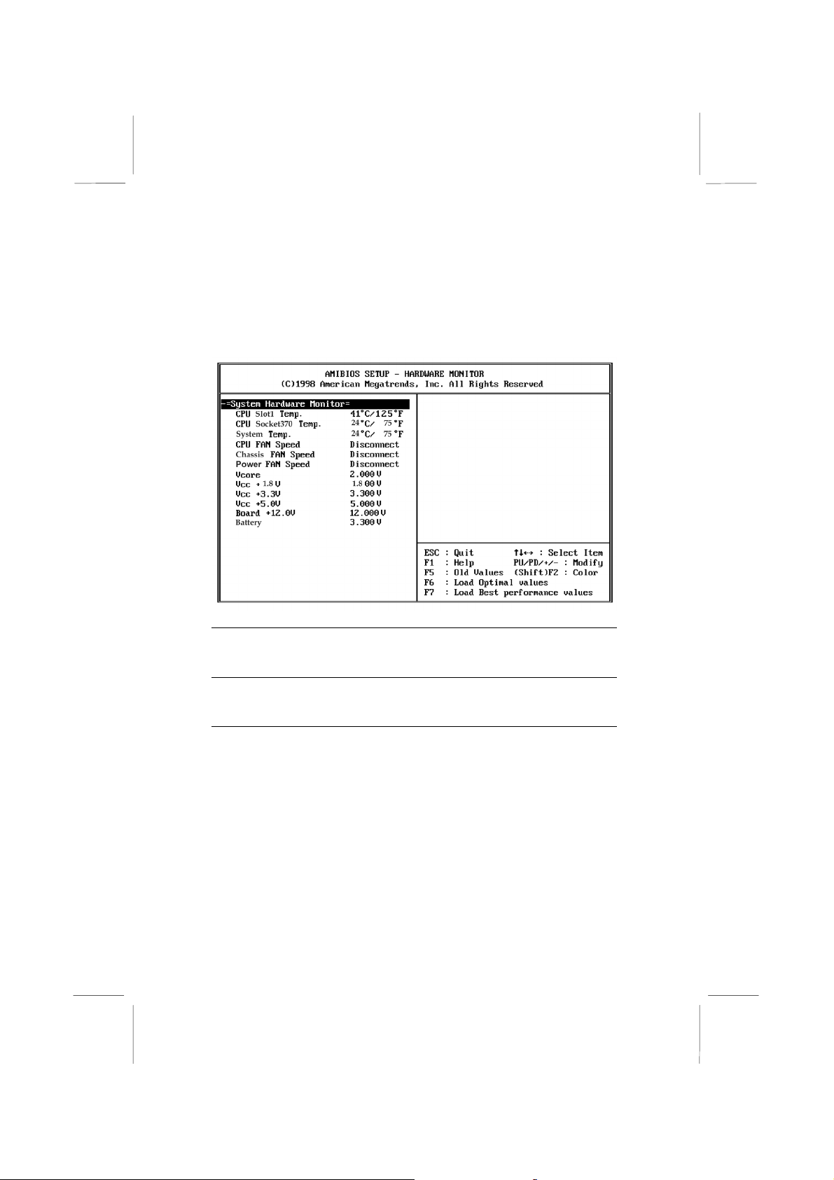
Hardware Monitor Page
This page sets some of the parameters for the hardware monitoring
function of this mainboard.
CPU Slot1 /
Socket370 &
System Temp.
Fan Speeds, VCCs
& Battery
Use these items to monitor the threshold
temperature for the CPU and the system
chassis.
Use these items to monitor the parameters for
the voltages that control the fans and the
mainboard.
Change Password
If you highlight this item and press Enter, a dialog box appears
which lets you enter a Supervisor password. You can enter no more
than six letters or numbers. Press Enter after you have typed in the
password. A second dialog box asks you to retype the password for
confirmation. Press Enter after you have retyped it correctly. The
password is required at boot time, or when the user enters the setup
utility.
Page 42

Change or Remove the Password
Highlight this item and type in the current password. At the next
dialog box, type in the new password, or just press Enter to disable
password protection.
Exit
Highlight this item and press Enter to save the changes that you
have made in the setup utility and exit the setup program. When
the Save and Exit dialog box appears, press Y to save and exit, or
press N to exit without saving.
Page 43
Chapter 4
Software & Applications
Introduction
The support software CD-ROM included in the mainboard package
contains all the drivers and utilities as needed to use our products.
Below you can find a brief description of each software program,
and the right location for your mainboard. More information on
each individual software might be available in a README file,
located in the same directory as the software.
If the operating system used in your system is Windows 98, it
will automatically install all the drivers and utilities for your
board. See the Auto-Installing Under Windows 98 section.
Installing the Drivers
The software on the support CD-ROM is for Windows 95/NT/2000
and Windows 98, but the automatic installation is now for Win98
only. If your operating system is not Windows 98, you have to
manually install for your drivers.
Installing Under Windows 95/NT/2000
1. In order to run the software put the support software CD-ROM
in the CD-ROM drive.
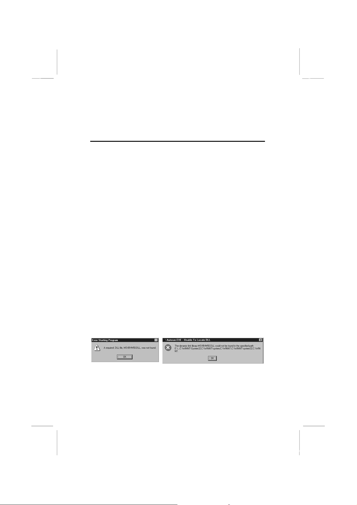
2. If your operating system is Windows 95/NT, the system might
get an error message as one of two pictures below from the
PnP function.
Don’t care the message, and click the OK button to exit. You
don’t really need the file to install the drivers.
If your operating system is Windows 2000, exit the Auto Set
Up window and go on.
Page 44

3. Use either My Computer or Windows Explorer to look at the
directory structure. You must use the Open command. Doubleclicking on the drive icon will not work.
4. Execute the EXE file name given in the description below.
Note: The correct path name for each software driver is provided,
where D: identifies the CD-ROM drive letter – modify if necessary.
Bus Master IDE Driver
The IDE Bus Master Drivers allows the system to properly manage
the IDE channels on the mainboard. You need to install two IDE
drivers if you are running Windows 9x.
Windows 9x – D:\IDE\Intel810\WIN9x\Intelinf\SETUP.EXE,
♦
and then, D:\IDE\Intel810\WIN9x\Infinst\SETUP.EXE
USB Driver
The USB Driver allows the system to recognize the USB ports on
the mainboard. You need to install this driver if you are running
Windows 95. This driver is available for:
Win95 – D:\USB\EUSBSUPP\USBSUPP.EXE
♦
♦ Win95 (Chinese) – D:\USB\CUSBSUPP\CUSBSUPP.EXE
Sound Driver
The Sound driver allows the system to generate optimal sound
effects. This driver is available for:
♦ DOS & Win3.x – D:\SOUND\Driver\M770LMRT\DosDrv\
♦ Windows 9x – D:\SOUND\Driver\M770LMRT\W95-98\Drv
♦ Windows NT – D:\SOUND\ Driver\M770LMRT\Nt40\Drv\
There are also two Audio applications available for:
♦ Windows 9x – D:\SOUND\Gamut\Audio Player
Windows 9x – D:\Yamaha-XG\S-YXG50
♦
Graphics Drivers and Software
Find the Graphics drivers and software here:
♦ D:\VGA\Intel810\Win9x\Graphics\SETUP.EXE
Page 45

Modem Drivers and Software
The Modem driver is required by the onboard modem module.
SuperVoice is a suite of modem applications for data and voice
transmissions. MediaRing Talk provides an internet telephone for
the onboard modem.
♦ D:\Modem\Driver\9xNT\Setup.exe
♦ D:\Modem\SuperVoice
D:\Modem\MediaRing Talk
♦
Network Adapter Driver
Find the network adapter driver here:
D:\LAN\Davicom9102
♦
BIOS Update Utility
The BIOS Update utility allows you to update the BIOS setup file
on your mainboard to a newer version. You can download the
latest version of the BIOS setup available for your mainboard from
the website.
♦ D:\UTILITY\AMIFL816.EXE
PC-Cillin Software
The PC-Cillin software program provides anti-virus protection for
your system. This program is available for:
♦ DOS – D:\PC-CILLIN\DOS\PCSCAN.EXE
♦ Windows 9x – D:\PC-CILLIN\WIN98\SETUP.EXE
ADCM Software
The AMI Desk-Client Management software provides network
management services. This software is available for:
♦ Windows 9x – D:\AMIADCM\Win9x\SETUP.EXE
Auto-Installing under Windows 98
During the installation under Win98 OS, the setup program will
automatically find out and match the proper drivers for the
hardware of your system. However, Windows might not be able to
detect some of your new hardware.
Please follow the steps listed below to install drivers and
applications for your system.
Page 46
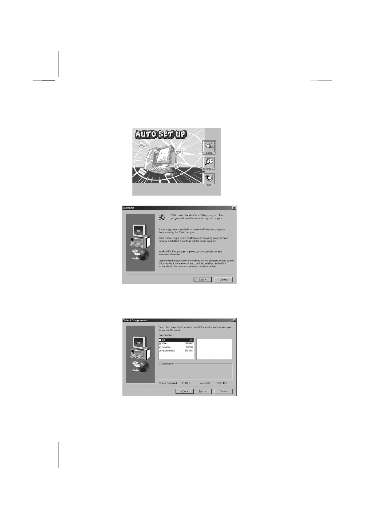
1. Put the support CD into CD-ROM drive.
2. The setup window will appear as below.
3. Click Setup button to continue.
4. Click Next button to continue.
5. Select the items that you want to setup by clicking on it (the
default options are recommended). Click the Next button to
proceed.
6. The support software will automatically install.
Page 47

Once any of the installation procedures start, software is
automatically installed in sequence. You will need to follow the
onscreen instructions, confirm commands and allow the computer
to restart as few times as is needed to complete installing whatever
software you selected to install. When the process is finished, all
the support software will be installed and working.
There are some utilities that you have to manually install if you
need, check to the above section.
Using the PCI Sound Pro Application
1. Before you install the Sound drivers, make sure your Operating
System has been installed, otherwise the PCI Sound Pro might
be detected as “Other device” by the device manager of your
OS.
2. After the drivers are properly installed, choose the
MULTIMEDIA icon in the CONTROL PANEL when you
need to use the Software Wave-Table drivers as a MIDI output
device. Select the MIDI page and click on “C-media SoftMidi
Synthesis (Win98) / Driver (Win95)”, then click “OK” to
confirm.
3. A Windows application named Audio Rack is provided with
the Sound drivers, which gives you control over all the audio
functions through a user interface that is as simple to use as a
home stereo system. We recommend that you use the System
Mixer in the Audio Rack software to control your computer’s
audio volume, recording device and the recording gain.
4. If the devices that you are using require the MIDI port as the
control interface, you need to select the MULTIMEDIA icon
in the CONTROL PANEL. Select the MIDI page and click on
“CM8738 MPU-401” (Win98) or “CM8738/C3DX PCI Audio
External MIDI Port” (Win95), and then click “OK” to confirm.
5. For more information, refer to the PCI Sound Pro manual in
the CD which ships with this mainboard.
Page 48

The Four Speakers System
The onboard Sound Pro audio system supports 2 wave channels
(front/rear) known as the 4 speaker system. If you are running
applications which use the DirectSound® 3D or A3D® audio
interface, your system can simulate realistic 3D sound through a 4
speaker setup. Follow the steps below to install a 4-speaker setup.
Speaker Installation
Connect the front two speakers to the Line-out jack on the sound
ports extension bracket. Connect the rear two speakers to the Linein/Rear jack on the sound ports extension bracket. The original
Line-in can be moved to Aux.
Speaker Position
Set up your speakers similar to the following figure to get the best
audio result.
Mixer Setup
There is a 4-speakers option in the Volume Control of the Mixer
when you are setting up the PCI Audio Application. Click on the 4
SPK icon to enable this option. This means that the output to the
rear speakers is sent through the Line-in/Rear jack. In order to
avoid hardware conflicts, DO NOT enable this option when the
Line-in/Rear jack is connected with a line-in device. While the 4
Page 49

speakers mode is enabled, turn on/off the output of the front
speakers and adjust the volume of the speakers so that the
front/rear speakers have the same volume.
Demo
Execute the “Helicopter” demo in the C3D HRTF Positional Audio
Demos of the PCI Audio Application. When you hear the
helicopter flying behind you, it means that the rear speakers are
working properly.
 Loading...