

Page 1

The information presented in this publication has been
carefully checked for reliability; however, no
responsibility is assumed for inaccuracies.
Specifications are subject to change without notice.
Trademarks
IBM, PC/AT, and PC/XT are trademarks of
International Business Machines Corporation.
Intel and Pentium are trademarks of Intel Corporation.
AMD is a trademark of Advanced Micro Devices Inc.
Cyrix is a trademark of Cyrix Corporation.
IDT is a trademark of Integrated Devices Technology
Corporation.
AMI is a trademark of American Megatrends Inc.
MS-DOS and WINDOWS NT are registered trademarks
of Microsoft Corporation.
Page 2

ii
Contents
Chapter 1: Introduction ...................................................................... 2
Key Features ................................................................................... 3
Unpacking the Mainboard & Static Electricity Precautions..... 5
Chapter 2: Hardware Configuration................................................ 7
Mainboard Component Locations ............................................... 8
Connectors....................................................................................... 9
PWR1 Ð AT Power Supply Connectors ............................... 9
COM1/2 Ð Serial Port #1/#2................................................. 9
PRN Ð Parallel Port ................................................................. 9
FDC Ð Floppy Disk Port ......................................................... 9
IDE1/IDE2 Ð Primary/Secondary IDE Ports...................... 9
PS1 Ð PS/2 Mouse Head Connector ..................................... 9
PS2 Ð PS/2 Mouse Pin Connector......................................... 9
KBD Ð Keyboard Connector .................................................. 9
J3 Ð ATX Form Card Connector ............................................ 9
J3 (1-4, 10-13) Ð 2 sets of Universal Serial Bus (USB)
Connectors ............................................................................... 9
J3 (5-6, 15-16) Ð PS/2 Mouse Connector ............................ 10
J3 (7-9, 17-18) Ð Infrared Connector.................................... 10
J2 (2, 4, 6, 8, 10) (KEY LOCK) Ð Keylock & Power LED
Connector ............................................................................... 10
J2 (1, 3, 5, 7) (SPK) Ð Speaker Connector............................ 10
J2 (13, 14) (TB-LED) Ð Turbo LED Connector ................... 11
J2 (15, 16) (HDD-LED) Ð HDD LED Connector ................ 11
J2 (17, 18) (RST) Ð Reset Switch Connector ....................... 11
J2 (19, 20) (SP-LED) Ð Suspend LED Connector ............... 11
J1 (FAN-PWR) Ð Fan Power ................................................ 11
Sound Pro Connectors:......................................................... 12
CD1/CD2 Ð Analog Audio for Sony/Panasonic ............. 12
J4 Ð Sound and Game ........................................................... 12
J7 Ð Digital Audio IN ............................................................ 12
J6 Ð Digital Audio OUT........................................................ 12
Jumper Settings ............................................................................ 13
JP1 Ð CMOS RAM Clear Selector* ...................................... 13
JP4 Ð DIMM Voltage Selectors** ......................................... 13
JP3 Ð CPU Type Selector ...................................................... 13
JP6 Ð CPU Core Voltage Selectors....................................... 13
JP5 (A, B) Ð CPU Internal Clock Speed Selectors ............. 14
JP7 (A, B) Ð CPU External Clock Selectors......................... 14
Page 3

iii
JP9 Ð Sound Pro Selector ...................................................... 14
J5 Ð MIC Type Selector ......................................................... 14
Memory Installation..................................................................... 15
Chapter 3: ACPI Functions & Connectors with ATX Power ..... 16
PWR2 Ð ATX Power Connector .......................................... 16
Software Power-Off .............................................................. 17
Modem Ring Power-On ....................................................... 17
Alarm Wake Up .................................................................... 17
J2 (21, 22) (PWRBT) Ð ATX Power Button and Suspend
Switch Connector .................................................................. 18
Chapter 4: BIOS Setup ..................................................................... 19
Entering WinBIOS Setup............................................................. 20
Default ........................................................................................... 21
Setup Window .............................................................................. 21
Standard Setup ...................................................................... 22
Advanced Setup .................................................................... 23
Chipset Setup......................................................................... 25
Power Management Setup................................................... 26
PCI/PnP Setup ...................................................................... 28
Peripheral Setup.................................................................... 30
Security .......................................................................................... 31
User ......................................................................................... 31
Anti-Virus............................................................................... 31
Utility ............................................................................................. 32
Detect IDE .............................................................................. 32
Exit WinBIOS Setup ..................................................................... 32
Save Changes and Exit ......................................................... 32
Do Not Save Changes and Exit ........................................... 32
Continue ................................................................................. 32
Page 4

Chapter 1
Introduction
The mainboard is a high-performance mainboard based
on the advanced Pentiumª microprocessor and
featuring PCI Local Bus and the high-end chipset. The
mainboard offers a high degree of flexibility in
configuration and is fully IBM PC/AT compatible.
Page 5

Introduction 3
Key Features
The advanced features of this mainboard include:
¥ Supports Pentiumª 90 ~ 300 MHz with
P54C/P55C (MMXª), Cyrix/IBM 6x86, 6x86L,
6x86MX (M2), IDT C6, and AMD K5/K6 CPUs at
60/66/75/83.3 MHz external clock speed
¥ Supports Write Allocation feature for AMD K6;
Error Checking & Correction (ECC) and Parity for
DRAM; Linear Wrap Mode for Cyrix M1, M2
¥ Supports 64M-bit (16Mx4, 8Mx8, 4Mx16)
DRAM/SDRAM technology
¥ Provides 4 x 72-pin SIMM and 3 x 168-pin DIMM to
support FPM/EDO/SDRAM modules ÒTable FreeÓ
configuration so that DIMM and SIMM can be
installed in any combinations up to 384MB
¥ Supports single piece of 72-pin SIMM working
capability
¥ Onboard 1MB (1024KB) Pipelined Burst
synchronous L2 cache
¥ Dual 20-pin ATX and 12-pin AT power connectors;
ATX power supports Modem Ring On, Suspend
Switch, and Alarm Wake Up
¥ Supports Ultra DMA/33 and ACPI
¥ Provides auto switching power between 2.2V and
3.5V for CPU Core voltage
¥ Supports 2.88MB, Iomega ZIP-100M, and IDE LS-
120 FDD, bootable from floppy, HDD ,CD-ROM,
SCSI, NetWork, LS-120, ZIP, or others
¥ 4 PCI Local Bus slots and 3 x 16 bits ISA Bus slots
¥ Onboard PCI Bus Master IDE interface supports 4
IDE devices with 2 channels; BIOS supports 4 IDE
harddisk drives which do not need device driver
Page 6

4 Chapter 1
for S/W application and the capacity of each
harddisk can be larger than 528MB and up to 8.4GB
¥ PCI IDE Controller supports PIO Mode 0 to Mode 4
and Ultra DMA/33 at maximum transfer rate of 33
MB/s and Bus Master IDE DMA Mode 2
¥ Onboard super Multi-I/O chip supports 2 serial
ports with 16550 fast UART compatible, 1 parallel
port with EPP and ECP capabilities, and one floppy
disk drive interface
¥ Supports PS/2 Mouse connecor and pin header
¥ Supports ATX FORM CARD containing PS/2
Mouse, USB interface x 2, and Infrared connectors
(optional)
¥ BIOS supports NCR810 SCSI BIOS firmware and
ÒPlug & PlayÓ Flash ROM
¥ Onboard Sound Pro supports the following
features:
Ñ Sound Blaster 16/PRO compatible with stereo
voice up to 48KHz sampling rates, HRTF 3D
Positional Audio Technology
Ñ Windows Sound System V2.0 compatible,
Accelerates Direct Sound 3D in Win95, and
Windows 95/31 & DOS drivers supported
Ñ Supports 44.1K digital audio (SPDIF) IN/OUT,
HSP-23 Wavetable synthesizer, full duplex 16bits CODEC with filters, and high quality 3D
sound (ON/OFF controllable)
Ñ Device supports SB16, WSS, & Game
Ñ Stereo Mixer supports analog mixing form CD-
Audio & Line-In and digital mixing from Voice,
FM/Wave-table, and digital CD-Audio.
Page 7

Introduction 5
Unpacking the Mainboard & Static
Electricity Precautions
This Mainboard package contains the following items:
1. The Mainboard
2. The Device Driver for this mainboard
3. This UserÕs Guide
4. Sound & Game ribbon cables/bracket
5. ATX Form Card (optional)
The mainboard is easily damaged by static electricity.
Follow the precautions below while unpacking or
installing the mainboard.
1. Do not remove the mainboard from its original
package until you are ready to install it.
2. Frequently ground yourself to discharge any static
electric charge that may build up in your body
while working on installation and/or
configuration. For example, you may ground
yourself by grasping an unpainted portion of the
systemÕs metal chassis.
3. Remove the mainboard from its anti-static
packaging and place it on a grounded surface,
component side up.
4. Handle the mainboard by its edges or by the
mounting bracket to avoid touching its
components.
Page 8

6 Chapter 1
5. Check the mainboard for damage. If any integrated
circuit appears loose, press carefully to seat it
firmly in its socket.
6. Do not apply power if the mainboard appears
damaged. If there is damage to the board contact
your dealer immediately.
Page 9

Chapter 2
Hardware Configuration
Before you install the mainboard into the system
chassis, you may find it convenient to first configure
the mainboardÕs hardware. This chapter describes how
to set jumpers and install memory modules, and where
to attach components.
Page 10
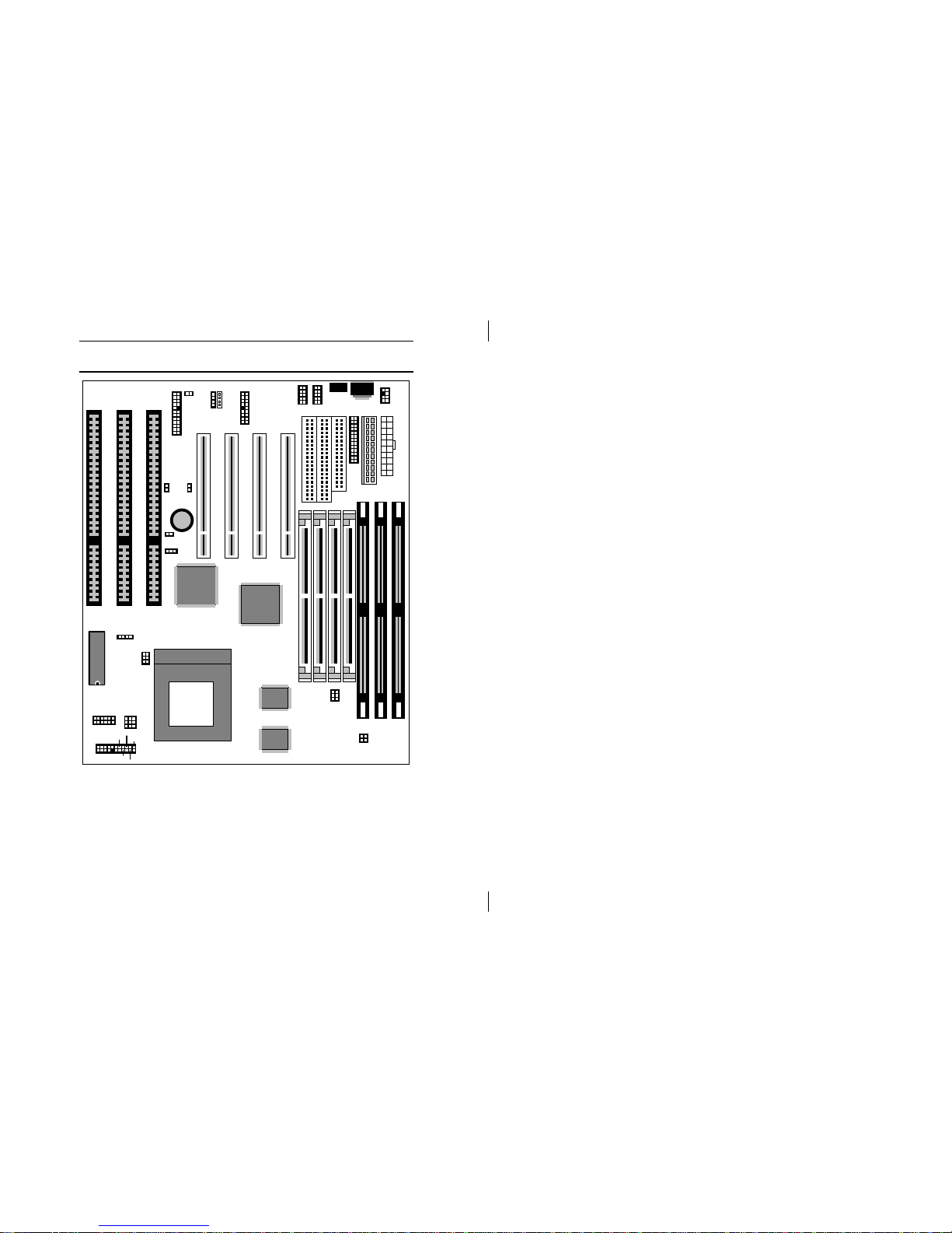
8 Chapter 2
Mainboard Component Locations
PCI4 PCI3 PCI2 PCI1
SIMM4SIMM3SIMM2SIMM1
DIMM1 DIMM2DIMM3
COM1 COM2
Socket 7
PWR1
14
Fan-PWR
PRN
PS1
JP6
ABCDEF
AB
JP4
JP3
1
BA
KBD
JP7
1
JP1
12 12
IDE2
1
FDC
1
CBA
JP5
1
3
J3
10 1
Battery
+
IDE1
1
PWR2
3.3V
5V
HDD-LED
SP-LED
SUS-SW
SPK
J2
1
2
21
22
+
+
TB-LED
RST
Keylock
12
PS2
Version
Cache
Cache
BIOS
Chipset
Chipset
1
CD1
CD2
J7J6
J5
26 13
1
J4
JP9
14
1
Figure 2Ð1. Mainboard Component Locations
Page 11

Hardware Configuration 9
Connectors
Attach system components and case devices to the
mainboard via the mainboard connectors. See Figure
2Ð1 for the location of the connectors on the mainboard.
Note: Make sure that the power is turned off before making
any connection to the board.
PWR1 – AT Power Supply Connectors
COM1/2 – Serial Port #1/#2
PRN – Parallel Port
FDC – Floppy Disk Port
IDE1/IDE2 – Primary/Secondary IDE Ports
PS1 – PS/2 Mouse Head Connector
PS2 – PS/2 Mouse Pin Connector
KBD – Keyboard Connector
J3 – ATX Form Card Connector
J3 (1-4, 10-13) – 2 sets of Universal Serial
Bus (USB) Connectors
USB USB
Pin Description Pin Description
1 +5V 10 +5V
2 Data Ð 11 Data Ð
3 Data + 12 Data +
4 Ground 13 Ground
Page 12

10 Chapter 2
J3 (5-6, 15-16) – PS/2 Mouse Connector
Pin Description
5 +5V
6 Mouse CLK
15 Mouse Data
16 Ground
J3 (7-9, 17-18) – Infrared Connector
Pin Description
7 Ground
8 Reserved
9 +5V
17 IR In
18 IR Out
J2 (2, 4, 6, 8, 10) (KEY LOCK) – Keylock &
Power LED Connector
Keylock connector enables and disables the keyboard
key-in function on the case.
Pin Description
2 LED Output
4 N.C.
6 Ground
8 Keylock
10 Ground
J2 (1, 3, 5, 7) (SPK) – Speaker Connector
Pin Description
1 Data Out
3 N.C.
5 Ground
7 +5V
Page 13

Hardware Configuration 11
J2 (13, 14) (TB-LED) – Turbo LED
Connector
Pin Description
13 (+) Anode
14 (Ð) Ground
J2 (15, 16) (HDD-LED) – HDD LED
Connector
Pin Description
15 (+) +5V
16 (Ð) Active Low
J2 (17, 18) (RST) – Reset Switch Connector
Attach the Reset push button cable to this connector.
Setting Description
Open Normal Mode
Close Reset System
J2 (19, 20) (SP-LED) – Suspend LED
Connector
Pin Description
19 (+) +5V
20 (Ð) Active Low
J1 (FAN-PWR) – Fan Power
Pin Description
1 +12V
2 Ground
3 Ground
4 +5V
Page 14

12 Chapter 2
Sound Pro Connectors:
CD1/CD2 – Analog Audio for
Sony/Panasonic
Connect to ÒAUDIOÓ on the CD-ROM drive.
J4 – Sound and Game
Sound contains Line-in/MIC (Microphone), and Lineout (Speaker). Game connector is also the Joystic
connector. Connect this connector to the Sound &
Game ribbon cable/bracket as the following drawing:
Line-In MIC Line-Out Game
J4 J4
J7 – Digital Audio IN
Depending on the type of your CD-ROM drive to
connect this connector to ÒDIGITAL AUDIOÓ on the
CD-ROM drive.
J6 – Digital Audio OUT
Connect to the Digital Audio Device.
Page 15
Hardware Configuration 13
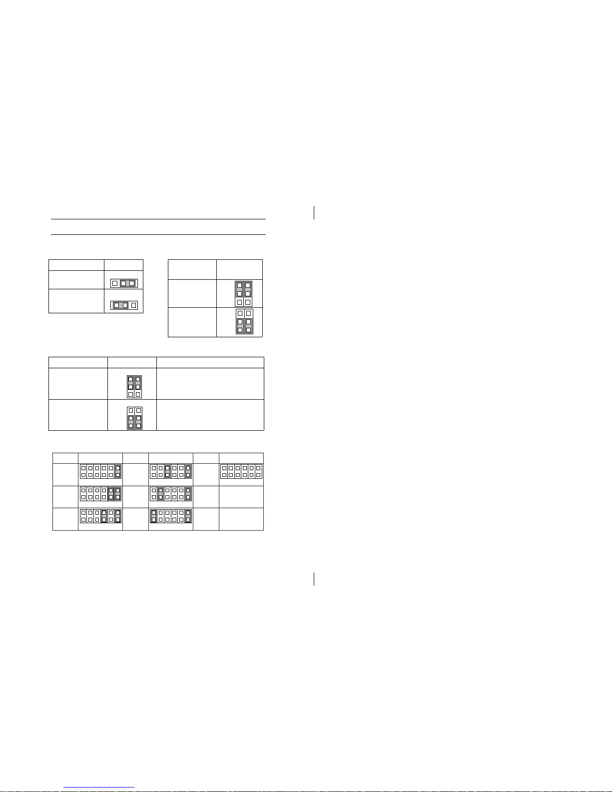
Jumper Settings
JP1 – CMOS RAM
Clear Selector*
Description Setting
Normal Mode
31
Clear CMOS
(default)
31
JP4 – DIMM Voltage
Selectors**
Voltage
Selectors
Setting
5V
15V
3.3V
3.3V
(default)
15V
3.3V
JP3 – CPU Type Selector
CPU Setting Example
P55C
(Dual Voltage)
(default)
AB
1
Intel MMXª,
AMD K6, IBM/Cyrix
6x86L/6x86MX(M2)
P54C
(Single Voltage)
AB
1
Intel P54C, IDT C6, AMD K5,
IBM/Cyrix 6x86
JP6 – CPU Core Voltage Selectors
EABCDF
ABCDEF
ABCDEF
ABCDEF
ABC ED F
E
ABCD F EFABCD
2.5V 3.2V
3.3V
3.5V2.9V
2.8V
(default)
Vcc Setting Vcc Setting
2.2V
Vcc Setting
* Make sure that the setting is set to Normal Mode before installing the
mainboard.
** The setting must be set to 3.3V position for all Synchronous DRAM.
Page 16
14 Chapter 2
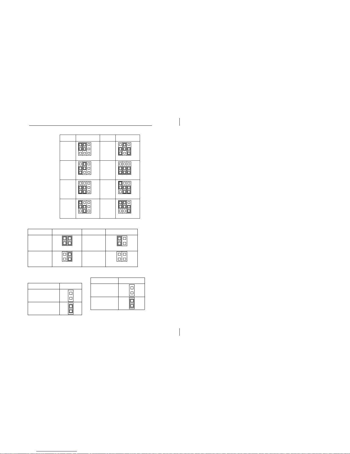
JP5 (A, B, C) – CPU Internal Clock Speed Selectors
1.5X/
3.5X
Internal Setting
CBA
4.0X
Internal Setting
CBA
2.0X
CBA
4.5X
CBA
2.5X
CBA
5.0X
CBA
CBA
5.5X3.0X
CBA
1
1
1
1
1
1
1
1
JP7 (A, B) – CPU External Clock Selectors
Clock Settings Clock Settings
60MHz
AB
75MHz
A B
66MHz
(default)
A B
83MHz
A B
JP9 – Sound Pro
Selector
Description Setting
Enabled
Disabled
J5 – MIC Type Selector
Description Setting
Standard
Special
Note: The CPU speed is equal to the CPU External Clock x CPU Internal Clock speed.
Page 17

Hardware Configuration 15
Memory Installation
The mainboard lets you add up to 384MB of system
memory through SIMM and DIMM sockets on the
board. Four SIMM sockets on the mainboard are
divided into two banks: Bank 0 and Bank 1. Each bank
consists of two 72-pin SIMM modules and three 168-pin
DIMM sockets are divided into three banks: Bank 0,
Bank 1, and Bank 2. The mainboard supports the
following memory configurations.
Bank Memory Module
Bank 0
SIMM1 & SIMM2
DIMM1
2 x 4MB/8MB/16MB/32MB/64MB
or
4MB, 8MB, 16MB, 32MB, 64MB, 128MB
Bank 1
SIMM3 & SIMM4
DIMM2
2 x 4MB/8MB/16MB/32MB/64MB
or
4MB, 8MB, 16MB, 32MB, 64MB, 128MB
Bank 2
DIMM3 4MB, 8MB, 16MB, 32MB, 64MB, 128MB
Total System Memory = Bank 0 + Bank 1 + Bank 2
Notes: 1. The following two types of DRAM module can not be used at
the same time: SIMM 1 & 2 and DIMM1 or SIMM3 & 4
and DIMM2.
2. Use 2 DRAM types: FPM/EDO faster than 70ns for SIMM
socket.
3. Use 3 DRAM types: FPM/EDO/SDRAM faster than 70ns
for DIMM socket.
Page 18

Chapter 3
ACPI Functions & Connectors
with ATX Power
PWR2 – ATX Power Connector
The ATX power supply provides a single 20-pin
connector and supports the ACPI specification.
Pin Description Pin Description
1 3.3V 11 3.3V
2 3.3V 12 Ð12V
3 Ground 13 Ground
4 +5V 14 PS-ON
5 Ground 15 Ground
6 +5V 16 Ground
7 Ground 17 Ground
8 Power OK 18 Ð5V
9 5VSB 19 +5V
10 +12V 20 +5V
Page 19

ATX Functions & Connectors 17
The functions and connectors described below work
with the ATX power supply.
Software Power-Off
Follow the steps below to use the ÒSoftware Power-Off
ControlÓ function in Windows 95 with ATX power
supply.
1. Click the START button on the Windows 95 task
bar.
2. Select Shut Down The Computer to turn off the
computer. The message ÒIt is now safe to turn off
your computer.Ó will not be shown when using this
function.
Modem Ring Power-On
While in Soft-off/Suspend state, if an external modem
ring-up signal occurs, the system wakes up and can be
remotely accessed. Make sure that the Ring Resume
From Soft Off option is set to Enabled in the BIOS setup
section (Refer to the Power Management section in
Chapter 4.)
Alarm Wake Up
If you want to autoboot the system at a certain time, set
the function of RTC Alarm time properly and the
function of RTC Alarm Resume From Soft Off option in
the BIOS Setup section will be set to Enabled.
Page 20

18 Chapter 3
J2 (21, 22) (PWRBT) – ATX Power Button and Suspend
Switch Connector
Attach the ATX Power Button or Suspend Switch cable
to this connector.
In the AT power system, this connector will act as a
suspend switch; and in the ATX power system, this
connector will be not only an ATX power button but a
Suspend switch as well. Details are described below:
When the system is off, push the power button to turn
the system on. When the system is on, push the power
button rapidly to switch the system to the Suspend
mode, and, by pushing and holding the button for
more than 4 seconds, it will turn the system completely
off. When the system is in the Suspend mode, push the
power button rapidly to turn the system on.
Page 21

Chapter 4
BIOS Setup
This chapter explains how to configure the mainboardÕs
BIOS setup program. The setup program provided
with the mainboard is the BIOS from AMI.
After you have configured the mainboard and have
assembled the components, turn on the computer and
run the software setup to ensure that the system
information is correct.
The software setup of the system board is achieved
through Basic Input-Output System (BIOS)
programming. You use the BIOS setup program to tell
the operating system what type of devices are
connected to your system board.
The system setup is also called CMOS setup. Normally,
you need to run system setup if either the hardware is
not identical with information contained in the CMOS
RAM, or if the CMOS RAM has lost power.
Note: When installing newer BIOS into this mainboard, you
must clear CMOS for a moment then set back to
Normal Mode, or hold down the <End> key then
power on to reboot the system.
Page 22
20 Chapter 4
Entering WinBIOS Setup
To enter the WinBIOS Setup program:
1. Turn on or reboot the system. A screen appears
with a series of diagnostic checks.
2. When ÒHit <DEL> if you want to run SETUPÓ
appears, press the <DEL> key to enter the BIOS
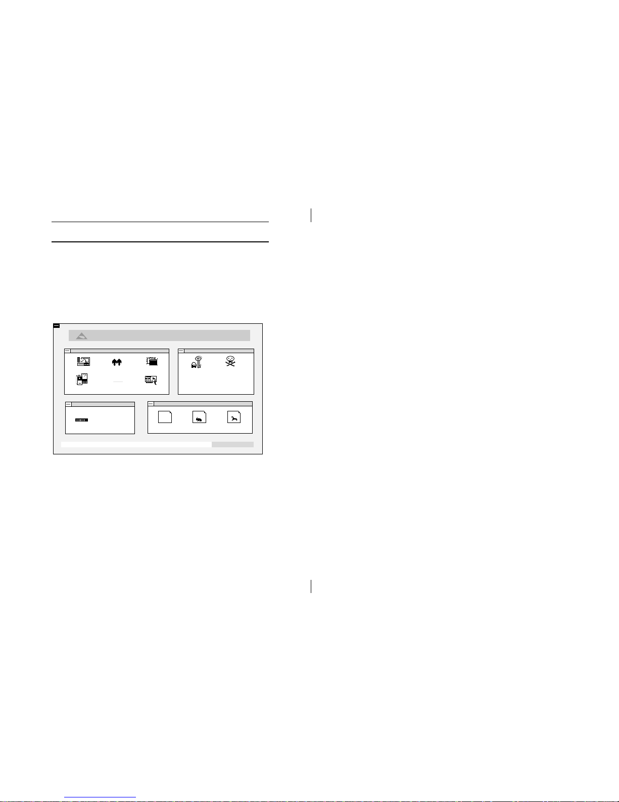
setup program. The following screen appears:
AMIBIOS Setup, Version - 2.4
(C) 1997, American Megatrends Inc.
American
Megatrends
Alt+H: Help
Set Date, Time, Floppy, Hard Disk
Default
Original Optimal Best
Security
User Anti-Virus
Setup
Standard Advanced Chipset
Power Mgmt
PCI/PnP Peripheral
P
CI
Utility
Detect IDE
3. Use your keyboard or mouse to choose options.
Modify system parameters to reflect system
options. Press Alt-H for Help.
Page 23
BIOS Setup 21
Default
Every option in the BIOS Setup contains three default
values: Original default, Best default, and the Optimal
default value.
Original: The original default values recover the
modified settings to the original values.
Optimal: The Optimal default values provide optimum
system settings for all devices and system
features.
Best: The Best default values provide best
performance settings for all devices and
system features, but dependent used devices
and we arenÕt guaranty that system run
overnight on these settings.
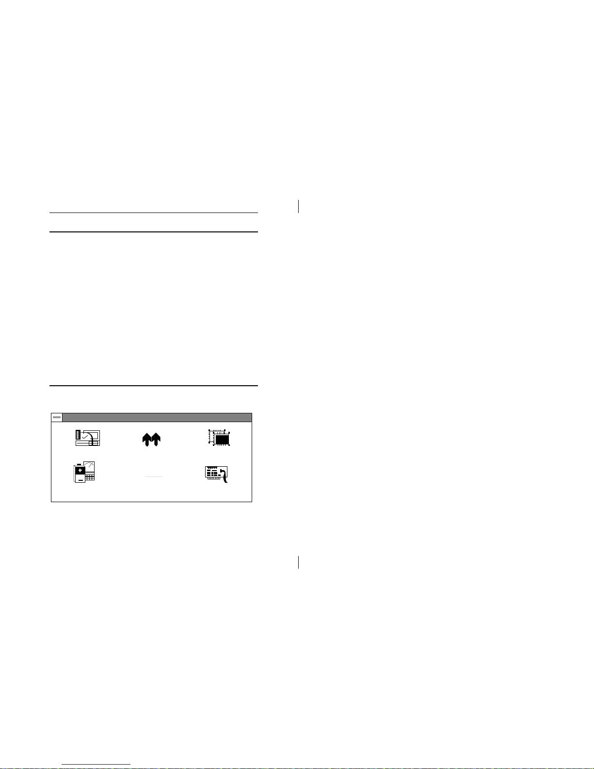
Setup Window
The Setup window has six icons that allow you to set
system configuration options.
Setup
Standard Advanced Chipset
Power Mgmt
PCI/PnP Peripheral
P
CI
Page 24

22 Chapter 4
Standard Setup
The WinBIOS Setup options described in this section
are displayed by choosing the Standard icon from the
Setup section on the WinBIOS Setup main menu. All
Standard Setup options are described in this section.
Pri Master
Pri Slave
Sec Master
Sec Slave
Choose these icons to configure the hard disk
drive named in the option. When you click on
an icon, the following parameters are listed:
Type, LBA/Large Mode, Block Mode, 32Bit
Mode, and PIO Mode. All parameters relate to
IDE drives except Type. Choose the Type
parameter and select Auto BIOS automatically
detects the IDE drive parameters and displays
them. Choose on LBA Mode and choose On to
enable support for IDE drives with capacities
greater than 528MB. Click on Blk Mode and
choose On to support IDE drives that use Blk
Mode. Click on 32Bit Mode and click on On to
support IDE drives that permit 32-bit accesses.
Date/Time Select the Date/Time option to change the date
or time. The current date and time are
displayed. Enter new values through the
displayed window.
Floppy Drive
A; B
Choose the Floppy Drive A or B icon to specify
the floppy drive type. The settings are 360KB
51/4", 1.2MB 51/4", 720KB 31/2", 1.44MB 31/2",
or 2.88MB 31/2".
Page 25

BIOS Setup 23
Advanced Setup
The WinBIOS Setup options described in this section
are displayed by choosing the Advanced icon from the
Setup section on the WinBIOS Setup main menu. All
Advanced Setup options are described in this section.
1st Boot Device;
2nd Boot Device;
3rd Boot Device;
4th Boot Device
Set these options to select the boot
sequence from different booting devices.
S.M.A.R.T for Hard
Disks
Select this option to enable or disable the
S.M.A.R.T. function of HDDs.
Quick Boot Set this option to Enabled to permit BIOS to
boot within 5 seconds.
Boot Up Num-Lock When this option is set to On, BIOS turns
off the Num Lock key when the system is
powered on so the end user can use the
arrow keys on both the numeric keypad
and the keyboard.
Floppy Drive Swap Set this option to Enabled to specify that
floppy drives A: and B: are swapped.
Floppy Drive Seek Choose Enabled or Disabled. Disabled
provides a faster boot and reduces the
possibility of damaging the heads.
PS/2 Mouse
Support
When this option is set to Enabled, BIOS
supports a PS/2 type mouse.
Page 26

24 Chapter 4
Password Check This option specifies the type of BIOS
password protection that is implemented.
The settings are:
Setup: The password prompt appears
only when an end user attempts
to run WinBIOS Setup.
Always: A password prompt appears
every time the computer is
powered on or rebooted.
The BIOS password does not have to be
enabled. The end user sets the password
by choosing the Password icon on the
WinBIOS Setup screen.
Internal Cache This option selects to enable the internal
cache or not.
External Cache This option selects to enable External
Cache or not.
System BIOS
Cacheable
BIOS always copies the system BIOS from
ROM to RAM for faster execution. Set this
option to Enabled to permit the contents of
the F0000h RAM memory segment to be
written to and read from cache memory.
Video BIOS
Shadow;
C800, 16K Shadow;
CC00, 16K Shadow;
D000, 16K Shadow;
D400, 16K Shadow;
D800, 16K Shadow;
DC00, 16K Shadow
Disabled: The specified ROM is not
copied to RAM.
Enabled: The contents of the ROM area
are not only copied from ROM
to RAM for faster execution, the
contents of the RAM area can
be written to or read from cache
memory.
Cached: The contents of the ROM area
are copied from ROM to RAM
for faster execution.
Page 27

BIOS Setup 25
Chipset Setup
Choose the Chipset icon from the Setup section on the
WinBIOS Setup main menu. All Chipset Setup options
are then displayed and are described in the following
section:
USB Function for
DOS
Set this option to enable the system BIOS
USB (Universal Serial Bus) functions.
DRAM Write
Timing
Set this option to select the proper DRAM
Write Timing.
Page Mode DRAM
Read Timing
Set this option to select the proper Page
Mode DRAM Read Timing.
RAS Precharge
Period
Set to select the RAS Precharge Period.
RAS to CAS Delay
Time
Set to select the Delay Time of RAS to CAS.
EDO DRAM Read
Timing
Set this option to select the proper EDO
DRAM Read Timing.
DRAM Speculative
Read
Set to enable the DRAM Speculative Read.
SDRAM CAS
Latency
Set this select the SDRAM CAS Latency.
SDRAM Timing Set to select the SDRAM Timing.
SDRAM
Speculative Read
Set to enable the SDRAM Speculative Read.
Pipe Function Set to enable the Pipe Function.
Page 28

26 Chapter 4
Slow Refresh Set to select the Slow Refresh.
DRAM Data
Integrity Mode
Set to select the DRAM Data Integrity
Mode.
Primary Frame
Buffer
Set to select the Primary Frame Buffer.
VGA Frame Buffer Set to enable the VGA Frame Buffer.
Passive Release Set to enable the Passive Release.
ISA Line Buffer Set to enable the ISA Line Buffer.
Delay Transaction Set to enable the Delay Transaction.
AT Bus Clock Set to select the AT Bus Clock.
Power Management Setup
The BIOS Setup options described in this section are
selected by choosing the Power Mgmt icon from the
Setup section on the WinBIOS Setup main menu.
Power
Management/
APM
Set this option to enable power management
features and APM (Advanced Power
Management).
Green PC Monitor
Power State
This option specifies the power state that the
green PC-compliant video monitor enters
when AMIBIOS places it in a power savings
state after the specified period of display
inactivity has expired.
Page 29

BIOS Setup 27
Video Power
Down Mode
This option specifies the power conserving
state that the VESA VGA video subsystem
enters after the specified period of display
inactivity has expired.
Hard Disk Power
Down Mode
This option specifies the power conserving
state that the hard disk drive enters after the
specified period of hard drive inactivity has
expired.
Standby Time out
(Minute)
This option specified the length of system
inactivity while in Full power on state. When
this length of time expires, the computer
enters Standby power state.
Suspend Time out
(Minute)
This option specified the length of a period of
system inactivity while in Standby state.
When this length of time expires, the
computer enters Suspend power state.
Monitor Parallel
Port;
Monitor serial
Port;
Monitor Floppy;
Monitor VGA;
Monitor Audio;
Monitor Pri-HDD;
Monitor Sec-HDD
When set to Yes, these options enable event
monitoring on the specified hardware
interrupt request line and the computer is in a
power saving state, BIOS watches for activity
on the specified IRQ line. The computer
enters the full on power state if any activity
occurs.
Power Button
Override
Set this option to enable Power Button
function.
Power Button
Function
This option specifies the operation of Soft-Off
by the Power Button. Select ÒGreenÓ function
to enter ÒOn-SuspendÐOffÓ or select ÒSoft
OffÓ function to enter ÒOn-OffÓ operation
cycle.
Page 30

28 Chapter 4
Ring Resume
From Soft Off
Set this option to enable the Modem Ring to
wake up the system which is Soft Off.
RTC Alarm
Resume From Soft
Off
Set this option to enable the RTC Alarm to
wake up the system which is Soft Off.
RTC Alarm Date;
RTC Alarm Hour;
RTC Alarm
Minute;
RTC Alarm
Second
Set these options to specify the RTC Alarm
time on Date/Hour/Minute/Second.
PCI/PnP Setup
Choose the PCI/PnP icon from the Setup section on the
WinBIOS Setup main menu.
OnBoard USB Set this option to enable USB function on
Chipset.
Plug and Play
Aware OS
Set this option to Yes if the operation system
in this computer is aware of and follows the
Plug and Play specification. Currently, only
Windows 95 is PnP-aware.
PCI Latency Timer
(PCI Clocks)
This option specifies the latency timings (in
PCI clocks) for all PCI devices on the PCI bus.
PCI VGA Palette
Snoop
When this option is set to Enabled, multiple
VGA devices operating on different buses can
handle data from the CPU on each set of
palette registers on every video device. Bit 5
of the command register in the PCI device
configuration space is the VGA Palette Snoop
bit (0 is disabled).
Page 31

BIOS Setup 29
OffBoard PCI IDE
Card
This option specifies if an offboard PCI IDE
controller adapter card is installed in the
computer. You must specify the PCI
expansion slot on the motherboard where the
offboard PCI IDE controller is installed. If an
offboard PCI IDE controller is used, the
onboard IDE controller is automatically
disabled. If an offboard PCI IDE controller
adapter card is installed in the computer, you
must also set the Offboard PCI IDE Primary
IRQ and Offboard PCI IDE Secondary IRQ
options.
OffBoard PCI IDE
Primary IRQ;
OffBoard PCI IDE
Secondary IRQ
These options specify the PCI interrupt used
by the Primary (or secondary) IDE channel on
the offboard PCI IDE controller.
Assign IRQ to PCI
VGA Card
Set this option to Enabled to assign IRQ to PCI
VGA Card.
PCI Slot 1/2/3/4/5
IRQ Priority
These options specify the priority IRQ to be
used for any PCI devices installed in PCI
expansion slots 1 through 5.
DMA Channel 0,
1, 3, 5, 6, 7
These options specify the bus that the
specified DMA channel is used on.
IRQ3, 4, 5, 7, 9, 10,
11, 12, 14, 15
These options specify the bus that the
specified IRQ line is used on. These options
allow you to reserve IRQs for legacy ISA
adapter cards.
Page 32

30 Chapter 4
Peripheral Setup
Choose the Peripheral icon from the Setup section on
the WinBIOS Setup main menu.
OnBoard FDC This option enables the FDC (Floppy Drive
Controller) on the motherboard or auto
detects the FDC.
OnBoard Serial
Port1
This option specifies the base I/O port
address of serial port 1.
Serial Port1 IRQ This option specifies IRQ to Serial Port 1.
OnBoard Serial
Port2
This option specifies the base I/O port
address of serial port 2.
Serial Port2 Mode This option specifies the serial port2 mode.
Normal: The normal serial port mode is
being used.
IrDA/ASKIR: The serial port2 will be
redirected to support IR function
when this option is set to IrDA or
ASKIR.
Serial Port2 IRQ This option specifies IRQ to Serial Port2.
IR Transmitter
Polarity;
IR Receiver
Polarity;
IR Half-Duplex
Time-Out
These options show up only when either
IrDA or ASKIR is chosen in the previous
option (Serial Port2 Mode).
OnBoard Parallel
Port
This option specifies the base I/O port
address of the parallel port on the
motherboard.
Page 33

BIOS Setup 31
Parallel Port Mode Depends on the type of your external device
which connects to this port to choose Normal,
Bi-Dir, EPP, or EPP/ECP mode.
EPP Version This option is only available if the setting of
the Parallel Port Mode option is set to EPP.
Parallel Port IRQ This option specifies IRQ to parallel port.
Parallel Port DMA
Channel
This option is only available if the setting of
the Parallel Port Mode option is EPP/ECP.
OnBoard IDE This option specifies the channel used by the
IDE controller on the motherboard.
OnBoard Sound
Pro
Set this option to enable the SoundPro
functions.
Security
User
This item lets you configure the system password
which is required every time when the system boots up
or an attempt is made to enter the Setup program. The
password cannot be longer than six characters.
Note: Keep a safe record of the new password. If you forget
or lose the password, the only way to access the system
is to discharge CMOS memory using Jumper JP1.
Anti-Virus
This item protects the boot sectors and partitions table
of your hard disk against accidental modifications.
Any attempt to write to boot sectors and partitions will
cause the system to halt and you need to use a bootable
none virus floppy disk to reboot the system and then
Page 34

32 Chapter 4
run the virus checking program to make sure that your
system is ok.
The default setting is ÒDisabled.Ó This setting is
recommended due to the conflicts within new
operating systems.
Utility
Detect IDE
If your system has an IDE hard drive, you can use this
utility to detect its parameters and automatically enter
them into the Standard CMOS Setup. This utility will
autodetect up to four IDE devices.
Exit WinBIOS Setup
Press the <ESC> key to exit the BIOS setup program
while in the main menu of the WinBIOS Setup and the
following three options will be displayed on the screen.
Save Changes and Exit
Select this item to save the values entered during the
current session and then exit the BIOS setup program.
Do Not Save Changes and Exit
Select this item to exit the BIOS setup program without
saving the values which has been entered during the
current session.
Continue
Select this item to return to the WinBIOS setup
program.
 Loading...