

Page 1

Motherboard User’s Guide
This publication, including photographs, illustrations and software, is under the
protection of international copyright laws, with all rights reserved. Neither this
guide, nor any of the material contained herein, may be reproduced without the
express written consent of the manufacturer.
The information in this document is subject to change without notice. The
manufacturer makes no representations or warranties with respect to the
contents hereof and specifically disclaims any implied warranties of merchantability or fitness for any particular purpose. Further, the manufacturer reserves
the right to revise this publication and to make changes from time to time in the
content hereof without obligation of the manufacturer to notify any person of
such revision or changes.
Trademarks
IBM, VGA, and PS/2 are registered trademarks of International Business
Machines.
AMD, Sempron, Athlon 64/Athlon 64 X2 Dual-core/Athlon 64 FX are registered trademarks of Advanced Micro Devices Inc.
Microsoft, MS-DOS and Windows 2000/XP are registered trademarks of Microsoft
Corporation.
AMI is a registered trademark of American Megatrends Inc.
Other names used in this publication may be trademarks and are acknowledged.
Static Electricity Precautions
1. Don’t take this motherboard and components out of their original staticproof package until you are ready to install them.
2. While installing, please wear a grounded wrist strap if possible. If you
don’t have a wrist strap, discharge static electricity by touching the bare
metal of the system chassis.
3. Carefully hold this motherboard by its edges. Do not touch those
components unless it is absolutely necessary. Put this motherboard on
the top of static-protection package with component side facing up
while installing.
Pre-Installation Inspection
1. Inspect this motherboard whether there are any damages to components
and connectors on the board.
2. If you suspect this motherboard has been damaged, do not connect
power to the system. Contact your motherboard vendor about those
damages.
Copyright © 2006
All Rights Reserved
A33G Series, V1.0
May 2006
i
Page 2

Motherboard User’s Guide
Table of Contents
Trademark ............................................................................................................i
Chapter 1: Introduction ..................................................................................... 1
Key Features .................................................................................................................... 1
Package Contents ........................................................................................................... 4
Chapter 2: Motherboard Installation .............................................................. 5
Motherboard Components ............................................................................................ 6
I/O Ports .......................................................................................................................... 7
Installing the Processor ................................................................................................. 7
Installing Memory Modules .......................................................................................... 8
Jumper Settings ............................................................................................................ 10
Install the Motherboard ............................................................................................... 10
Connecting Optional Devices .....................................................................................1 2
Install Other Devices .................................................................................................... 14
Expansion Slots ............................................................................................................ 16
Chapter 3: BIOS Setup Utility ....................................................................... 18
Introduction .................................................................................................................. 18
Running the Setup Utility ................................................... …………………………...18
Standard CMOS Setup Page .......................................................................................1 9
Advanced Setup Page .................................................................................................. 20
Features Setup Page .................................................................................................... 21
Power Management Setup Page ................................................................................2 3
PCI/Plug and Play Setup Page .................................................................................. 24
BIOS Security Features Setup Page ........................................................................... 2 5
CPU PnP Setup Page .................................................................................................. 2 5
Hardware Monitor Page .............................................................................................. 26
Load Best Performance Settings ................................................................................. 2 7
Load Optimal Defaults ................................................................................................2 7
Save Changes and Exit ................................................................................................ 27
Discard Changes and Exit ........................................................................................... 27
Chapter 4: Software & Applications .............................................................. 28
Introduction .................................................................................................................. 2 8
Installing Support Software ........................................................................................2 8
Bundled Software Installation ....................................................................................3 0
ii
Page 3
Motherboard User’s Guide
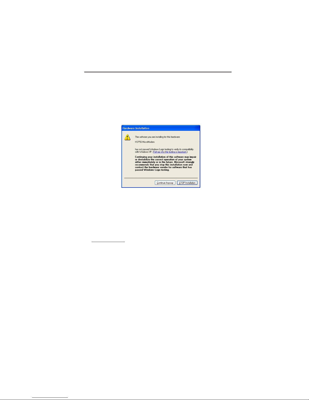
Notice:
1. Owing to Microsoft’s certifying schedule is various to every supplier, we
might have some drivers not certified yet by Microsoft. Therefore, it
might happen under Windows XP that a dialogue box (shown as below)
pops out warning you this software has not passed Windows Logo
testing to verify its compatibility with Windows XP. Please rest assured
that our RD department has already tested and verified these drivers.
Just click the “Continue Anyway” button and go ahead the installation.
2. USB 2.0 Driver Limitations:
2-1. The USB 2.0 driver only supports Windows XP and Windows 2000.
2-2. If you connect a USB 2.0 hub to the root hub, plugging USB devices
into this hub, the system might not successfully execute certain USB
devices’ connection because it could not recognize these devices.
Currently, we are working on such limitations’ solution. As soon as the
olution is done, the updated USB drive will be released to our website:
www.pcchips.com for your downloading.
iii
Page 4
1
Motherboard User’s Guide
Chapter 1 Introduction
This motherboard has a Socket-AM2 supporting the newest and advanced AMD
Sempron/Athlon 64/Athlon 64 X2 Dual-Core/Athlon 64 FX with HyperTransport
Technology processors and Front-Side Bus (FSB) speeds up to1000 MHz.
It integrates the SiS761GX Northbridge and SiS965L Southbridge that supports
the built-in USB 2.0 providing higher bandwidth, implementing Universal Serial
Bus Specification Revision 2.0. It supports AC’ 97 Audio Codec and provides
Ultra DMA 133/100/66 function. It has one PCI Express x16, one PCI Express
x1, one CNR and two 32-bit PCI slots. There is a full set of I/O ports including
two PS/2 ports for mouse and keyboard, one serial port, one parallel port, one
LAN port(optional), one VGA port, three audio jacks for Line-in, Line-out and
Microphone, four back-panel USB2.0 ports and onboard USB headers providing
extra ports by connecting the Extended USB Module to the motherboard.
This motherboard is a Micro ATX size motherboard and has power connectors
for an ATX power supply.
Key Features
The key features of this motherboard include:
Socket-AM2 Processor Support
• Supports AMD Sempron/Athlon 64/Athlon 64 X2 Dual-Core/Athlon 64
FX processors
• Supports Front-Side Bus 1000 MHz
Note: HyperTransport Technology is a point-to-point link between two
devices, it enables integrated circuits to exchange information at much
higher speeds than currently available interconnect technologies.
Chipset
There are SiS761GX Northbridge and SiS965L Southbridge in this chipset in
accordance with an innovative and scalable architecture with proven reliability
and performance.
• High Performance Host Interface:
-Supports AMD Athlon 64, Athlon 64 FX, Sempron CPUs
−HyperTransport compliant bus driver with auto compensation
capability
• Integrated Host-to-PCI Express Bridge:
−4 GB/s bandwidth for each direction
−Compliant with PCI Express SPEC 1.0a
• High Performance & High Quality 3D Graphics Accelerator:
−Built-in 32-bit floating point format VLIM triangle setup engine
−Built-in 2 pixel rendering pipelines and 4 texture units
Page 5

2
Motherboard User’s Guide
• PCI 2.3 Specification Compliance
• Integrated Multithreaded I/O Link Mastering
• Multithread I/O Link Mastering with Read/Write Concurrent and Read/
Read Pipeline Transaction
Memory Support
• Two 240-pin DIMM sockets for DDR SDRAM memory modules
• Supports DDR2 800/667/533/400 memory bus
• Maximum installed memory is 16 GB
Expansion Slots
• One PCI Express x1 slot
• One PCI Express x16 slot
• Two 32-bit PCI slots for PCI 2.3 compliant bus interface
• One optional CNR slot
Onboard IDE channels
• Two IDE Connectors
• Supports PIO (Programmable Input/Output) and DMA (Direct Memory
Access) modes
• Supports IDE Ultra DMA bus mastering with transfer rates of 133/100/
66 MB/sec
Serial ATA
• Two Serial ATA Connectors
• Transfer rate exceeding best ATA (~1.5 Gb/s) with scalability to higher
rates
• Low pin count for both host and devices
AC’97 Codec
Onboard I/O Ports
• Two PS/2 ports for mouse and keyboard
• One serial port
• One parallel port
• One VGA port
• Four back-panel USB2.0 ports
• One LAN port (optional)
• Audio jacks for microphone, line-in and line-out
• Compliant with the AC’97 v2.3 CODEC
• Supports 6-channel audio CODEC designed for PC multimedia systems
• Provides three analog line-level stereo inputs with 5-bit volume control:
Line-in, CD, AUX
• Meets Microsoft WHQL/WLP 2.0 audio requirements
Page 6

3
Chapter 1: Introduction
Fast Ethernet LAN (optional)
• Supports 10BASE-T/100BASE-TX IEEE 802.3u fast Ethernet trans-
ceiver
• Integrated voltage regulator to allow operation from a single 3.3 V/2.5V
supply source
• Supports MII and 7-wire serial interface
• Supports low-power mode
USB 2.0
• Compliant with Universal Serial Bus Specification Revision 2.0
• Compliant with Intel’s Enhanced Host Controller Interface Specification
Revision 1.0
• Compliant with Universal Host Controller Interface Specification
Revision 1.1
• PCI multi-function device consists of two UHCI Host Controller cores
for full-/low-speed signaling and one EHCI Host Controller core for
high-speed signaling
• Root hub consists 4 downstream facing ports with integrated physical
layer transceivers shared by UHCI and EHCI Host Controller, up to
eight functional ports
• Support PCI-Bus Power Management Interface Specification release 1.1
• Legacy support for all downstream facing ports
BIOS Firmware
This motherboard uses AMI BIOS that enables users to configure many system
features including the following:
• Power management
• Wake-up alarms
• CPU parameters and memory timing
• CPU and memory timing
The firmware can also be used to set parameters for different processor clock
speeds.
Dimensions
• Micro ATX form factor of 244 x 200 mm
Note: Hardware specifications and software items are subject to change
without notification.
Page 7

4
Motherboard User’s Guide
Package Contents
Your motherboard package ships with the following items:
The motherboard
The User’s Guide
One diskette drive ribbon cable (optional)
One IDE drive ribbon cable
The Software support CD
Optional Accessories
You can purchase the following optional accessories for this motherboard.
The Extended USB module
The CNR v.90 56K Fax/Modem card
The Serial ATA cable
The Serial ATA power cable
Note: You can purchase your own optional accessories from the third party,
but please contact your local vendor on any issues of the specification
and compatibility.
Page 8

Chapter 2: Motherboard Installation
Chapter 2 Motherboard Installation
To install this motherboard in a system, please follow these instructions in this
chapter:
Identify the motherboard components
Install a CPU
Install one or more system memory modules
Make sure all jumpers and switches are set correctly
Install this motherboard in a system chassis (case)
Connect any extension brackets or cables to headers/connectors on the
motherboard
Install peripheral devices and make the appropriate connections to
headers/connectors on the motherboard
Note:
1 Before installing this motherboard, make sure jumper CLR_CMOS1
is under Normal setting. See this chapter for information about
locating CLR_CMOS1 and the setting options.
2 Never connect power to the system during installation; otherwise, it
may damage the motherboard.
5
Page 9
Motherboard User’s Guide
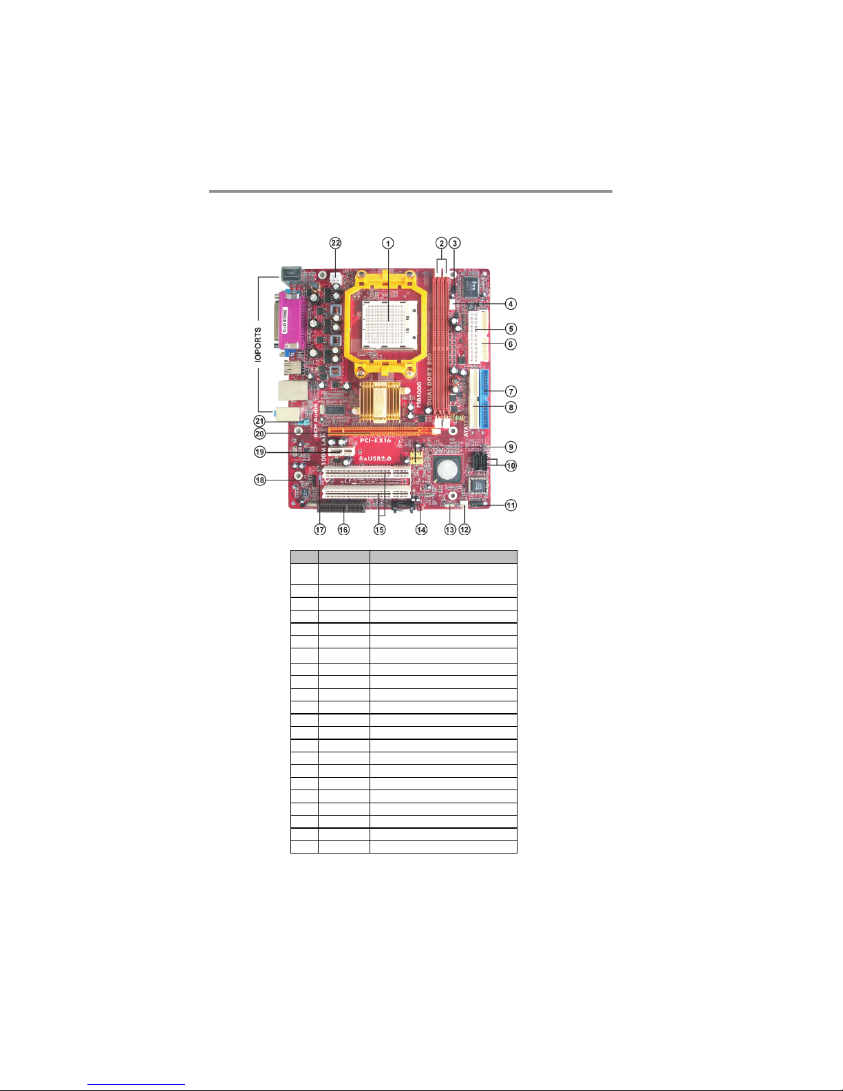
Motherboard Components
IT EM LA BEL COM P ONENTS
1CPU Socket
2 DDRII1~2 24 0-p in DDR2 SDRA M so cket s
3 IR1 Infrared header
4 CPU_FA N1 CPU Fan connec tor(4 PIN)
5 PWR1 Standard 24-Pin ATX Pow er connector
6 FDD1 Floppy Disk Drive connector
7 IDE1 Primar y IDE connec tor
8 IDE2 Secondar y IDE c onnector
9 F_USB1/2 Front Panel USB headers
10 SATA1/2 Serial ATA connec tors
11 PANEL1 Front Panel Sw itch/LED header
12 SYS_FA N1 Sys tem Fan connector
13 SPK1 Speaker header
14 CL R_CMOS1 Cle ar CMOS j umpe r
15 PCI1- 2 32-bit PCI slots
16 CNR1 CNR sl ot
17 SPDIFO1 SPDIF Out header
18 CD_IN1 Analog Audio Input header
19 PCI- E2 PCI Ex pr es s x 1 s lo t
20 PCI- E1 PCI Ex press x16 s lot
21 F_AUDIO1 Front Panel Audio header
22 PWR2 Standard 4-Pin ATX Pow er connec tor
Socket A M2 for AMD Athlon 64/Athlon
64 X2 Dual-Core/At hlon 64 FX CPUs
6
Page 10
Chapter 2: Motherboard Installation
I/O Ports
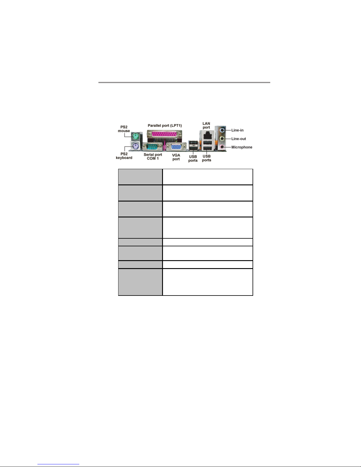
The illustration below shows a side view of the built-in I/O ports on the
motherboard.
PS/2 Mouse
PS/2 Ke ybo ar d
Par alle l Po r t (LPT1)
Serial Por t (COM1)
VGA Port
LAN Port (optional)
USB Por t s
Audio Port s
Use the upper PS/2 port to connect a PS/2 pointing
devic e.
Use the low er PS/2 port to connect a PS/2
key boar d.
Us e the Parallel port to connect printers or other
parallel communications devices .
Us e the COM port to connect serial devices such
as mice or f ax/modems. COM1 is identif ied by the
system as COM1.
Us e the VGA port to connect VGA devices.
Connect an RJ-45 jack to the LAN port to connec t
your computer to the Netw ork.
Use the USB ports to c onnec t USB devices.
Us e these three audio jacks to connect audio
devices . The fir st jack is f or s tereo Line-In signal,
the s econd jack f or stereo Line- Out signal, and t he
thir d jac k for Micr ophone.
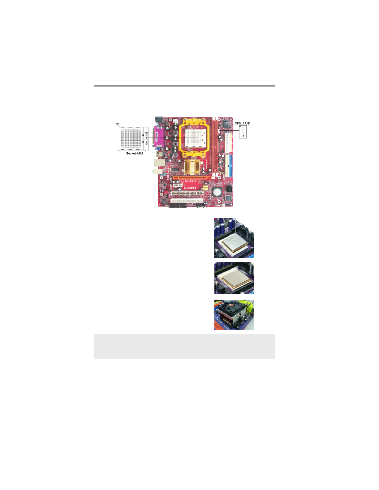
Installing the Processor
This motherboard has a socket AM2 processor socket. When choosing a processor,
consider the performance requirements of the system. Performance is based on the
processor design, the clock speed and system bus frequency of the processor, and
the quantity of internal cache memory and external cache memory.
7
Page 11
Motherboard User’s Guide
CPU Installation Procedure
Follow these instructions to install the CPU:
1 Unhook the locking lever of the CPU socket.
Pull the locking lever away from the socket
and raising it to the upright position.
2 Match the pin1 corner marked as the beveled
edge on the CPU with the pin1 corner on the
socket. Insert the CPU into the socket. Do
not use force.
3 Push the locking lever down and hook it un-
der the latch on the edge of socket.
4 Apply thermal grease to the top of the CPU.
5 Install the cooling fan/heatsink unit onto the
CPU, and secure them all onto the socket
base.
6 Plug the CPU fan power cable into the CPU
fan connector (CPU_FAN1) on the
motherboard.
Note: To achieve better airflow rates and heat dissipation, we suggest that
you use a high quality fan with 4800 rpm at least. CPU fan and heatsink
installation procedures may vary with the type of CPU fan/heatsink
supplied. The form and size of fan/heatsink may also vary.
Installing Memory Modules
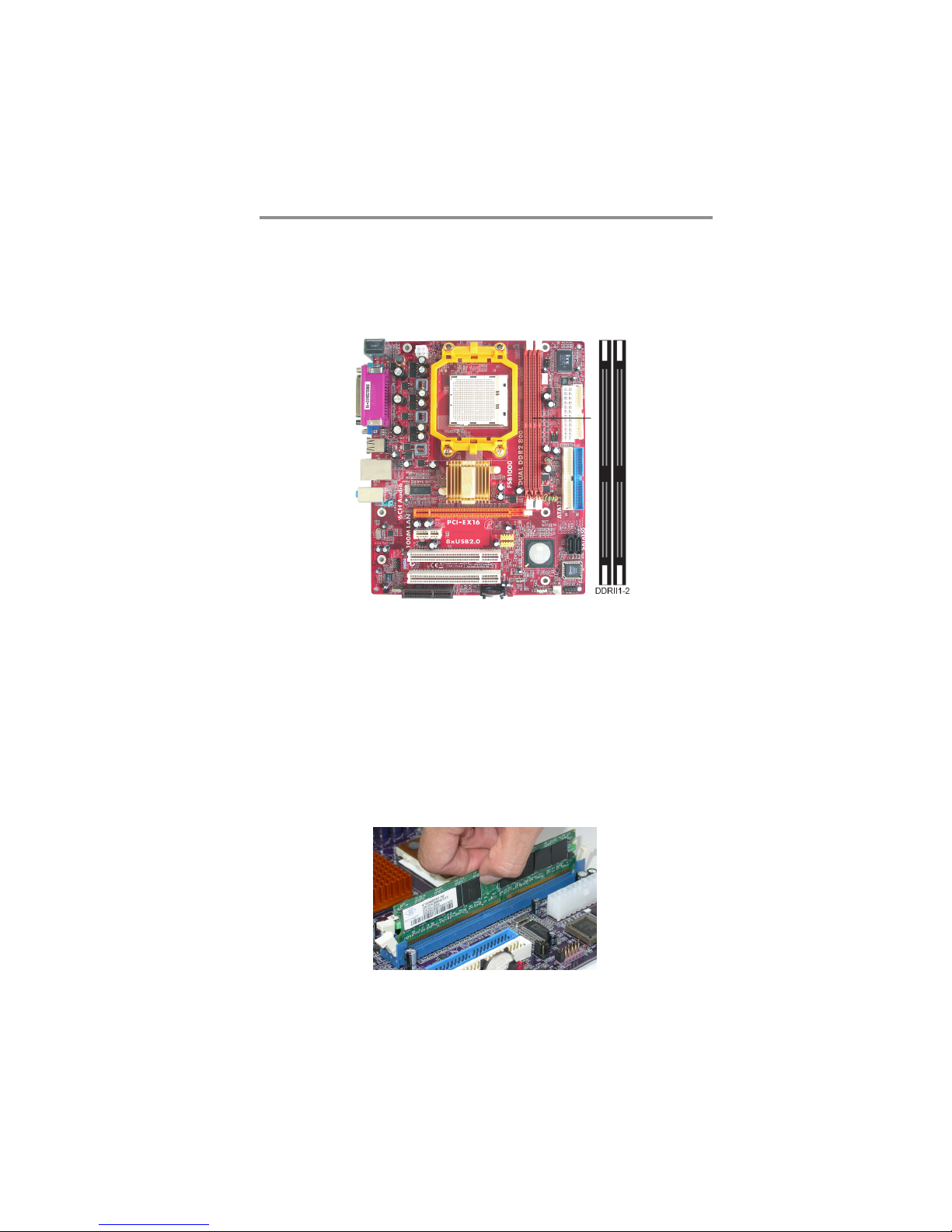
This motherboard accommodates two 240-pin DIMM sockets (Dual Inline Memory
Module) for unbuffered DDR2 800/667/533/400 memory modules (Double Data
Rate SDRAM), and maximum 16 GB installed memory.
8
Page 12
Chapter 2: Motherboard Installation
Over its predecessor, DDR2-SDRAM offers greater bandwidth and density in a
smaller package along with a reduction in power consumption. In addition, DDR2SDRAM offers new features and functions that enable a higher clock rate and data
rate operations of 400 MHz, 533 MHz 667 MHz and 800 MHz. DDR2 transfers
64 bits of data twice every clock cycle.
Memory Module Installation Procedure
These modules can be installed with up to 16 GB system memory. Refer to the
following to install the memory module.
1. Push down the latches on both sides of the DIMM socket.
2. Align the memory module with the socket. There is a notch on the DIMM
socket that you can install the DIMM module in the correct direction.
Match the cutout on the DIMM module with the notch on the DIMM
socket.
3. Install the DIMM module into the socket and press it firmly down until it
is seated correctly. The socket latches are levered upwards and latch on to
the edges of the DIMM.
4. Install any remaining DIMM modules.
9
Page 13
Motherboard User’s Guide
Note for dual-channel DDR2:
1. You CAN NOT use only one DIMM2 for it might cause the system shutdown.
2. You need to use DIMM1 and DIMM2 with the same size of memory modules.
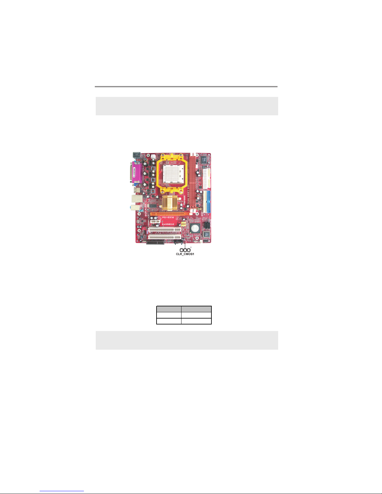
Jumper Settings
Connecting two pins with a jumper cap is SHORT; removing a jumper cap from
these pins, OPEN.
CLR_CMOS1: Clear CMOS Jumper
Use this jumper to clear the contents of the CMOS memory. You may need to clear
the CMOS memory if the settings in the Setup Utility are incorrect and prevent
your motherboard from operating. To clear the CMOS memory, disconnect all the
power cables from the motherboard and then move the jumper cap into the CLEAR
setting for a few seconds.
Note: To avoid the system unstability after clearing CMOS, we recommend
users to enter the main BIOS setting page to “Load Optimal De-faults”
and then “Save Changes and Exit”.
Function Jumpe r
Clear CMOS Short Pins 1-2
NORMAL Short Pins 2-3
10
Page 14
Chapter 2: Motherboard Installation
Install The Motherboard
Install the motherboard in a system chassis (case). The board is a Micro ATX size
motherboard. You can install this motherboard in an ATX case. Make sure your
case has an I/O cover plate matching the ports on this motherboard.
Install the motherboard in a case. Follow the case manufacturer’s instructions to
use the hardware and internal mounting points on the chassis.
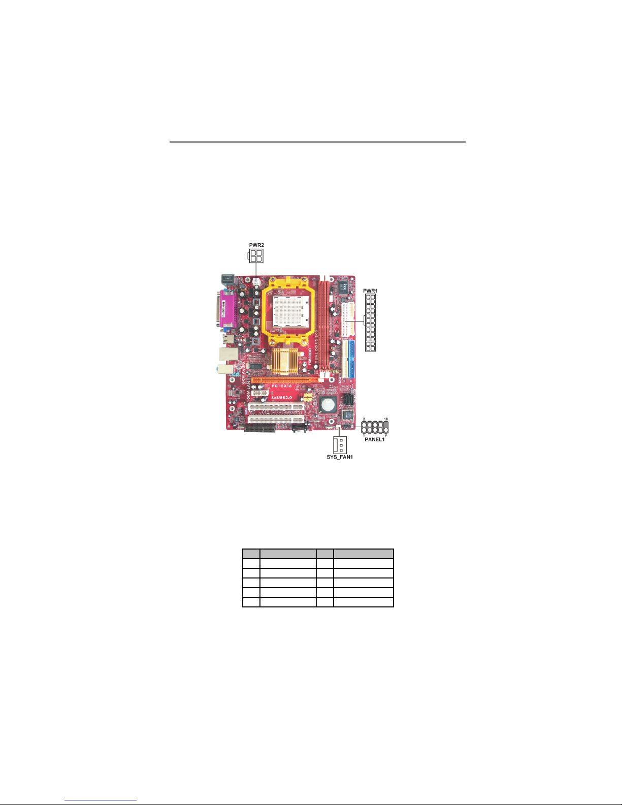
Connect the power connector from the power supply to the PWR1 connector on
the motherboard. PWR2 is a +12V connecotr for CPU Vcore power.
If there is a cooling fan installed in the system chassis, connect the cable from the
cooling fan to the SYS_FAN1 fan power connector on the motherboard.
Connect the case switches and indicator LEDs to the PANEL1 header.
Pin Signal Pin Sign al
1 HD_L ED_P( +) 2 FP PWR/SL P( +)
3 HD_L ED_N( - ) 4 FP PWR/SLP( -)
5 RES ET_ S W_ N( - ) 6 PO WER_ S W_ P( +)
7 RES ET_ S W_ P( +) 8 POW ER_ SW _ N( - )
9 RSV D_DNU 10 K EY
11
Page 15
Motherboard User’s Guide
Connecting Optional Devices
Refer to the following for information on connecting the motherboard’s optional
devices:
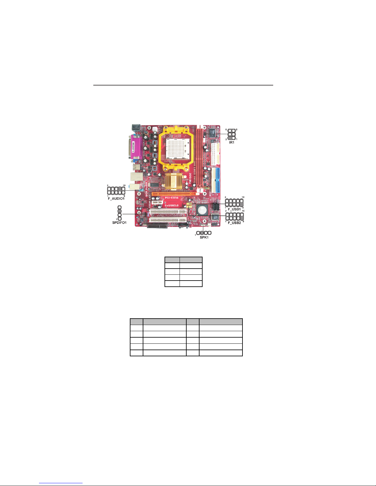
SPK1: Speaker Header
Connect the cable from the PC speaker to the SPK1 header on the motherboard.
Pin Sign al
1 +5V
2NC
3GND
4SPKR
F_AUDIO1: Front Panel Audio Header
This header allows the user to install auxiliary front-oriented microphone and lineout ports for easier access.
Pin Signal Pin Signal
1AUD_MIC 2AUD_GND
3 A UD_MIC_BIAS 4 A UD_VCC
5 A UD_FPOUT_R 6 A UD_RET_R
7NC 8KEY
9 A UD_FPOUT_L 10 AUD_RET_L
12
Page 16
Chapter 2: Motherboard Installation
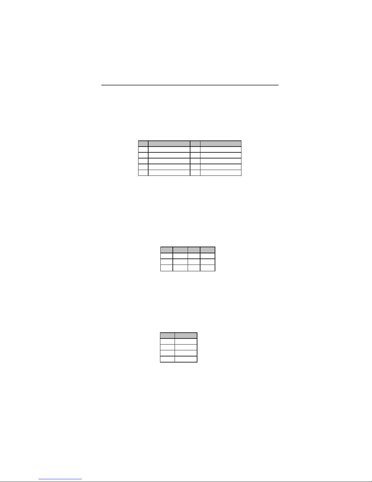
F_USB1~2: Front Panel USB Headers
The motherboard has USB ports installed on the rear edge I/O port array. Additionally, some computer cases have USB ports at the front of the case. If you have this
kind of case, use auxiliary USB headers F_USB1~2 to connect the front-mounted
ports to the motherboard.
Here is a list of USB pin assignments.
Pin Signal Pin Signal
1 V ERG_FP_USBPWR0 2 VERG_FP_USBPWR0
3 USB_FP_P0(-) 4 USB_FP_P1(-)
5 USB_FP_P0(+) 6 USB_FP_P1(+)
7 GROUND 8 GROUND
9 KEY 10 GROUND
1. Locate the F_USB1~2 headers on the motherboard.
2. Plug the bracket cable onto the F_USB1~2 headers.
3. Remove a slot cover from one of the expansion slots on the system chassis.
Install an extension bracket in the opening. Secure the extension bracket to
the chassis with a screw.
IR1: Infrared Port Header
The infrared port allows the wireless exchange of information between your computer and similarly equipped devices such as printers, laptops, Personal Digital
Assistants (PDAs), and other computers.
Pin Signal Pin Signal
1NC2KEY
3+5V 4GND
5 IRTX 6 IRRX
1. Locate the infrared port-IR1 header on the motherboard.
2. If you are adding an infrared port, connect the ribbon cable from the port to
the IR1 header and then secure the port to an appropriate place in your
system chassis.
SPDIFO1: SPDIF out header
This is an optional header that provides an S/PDIF (Sony/Philips Digital Interface)
output to digital multimedia device through optical fiber or coaxial connector.
Pin Sign al
1SPDIF
2 +5VA
3Key
4GND
13
Page 17
Motherboard User’s Guide
Install Other Devices
Install and connect any other devices in the system following the steps below.
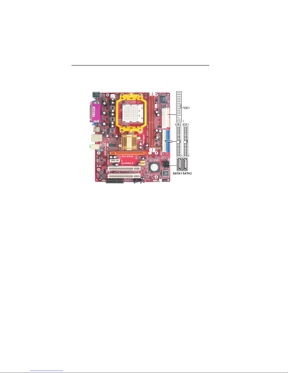
Floppy Disk Drive
The motherboard ships with a floppy disk drive cable that can support one or
two drives. Drives can be 3.5" or 5.25" wide, with capacities of 360K, 720K,
1.2MB, 1.44MB, or 2.88MB.
Install your drives and connect power from the system power supply. Use the
cable provided to connect the drives to the floppy disk drive connector FDD1.
IDE Devices
IDE devices include hard disk drives, high-density diskette drives, and CD-ROM
or DVD-ROM drives, among others.
The mainboard ships with an IDE cable that can support one or two IDE
devices. If you connect two devices to a single cable, you must configure one of
the drives as Master and one of the drives as Slave. The documentation of the
IDE device will tell you how to configure the device as a Master or Slave device.
The Master device connects to the end of the cable.
Install the device(s) and connect power from the system power
supply. Use the cable provided to connect the device(s) to the Primary IDE
channel connector IDE1 on the motherboard.
14
Page 18
Chapter 2: Motherboard Installation
If you want to install more IDE devices, you can purchase a second IDE cable and
connect one or two devices to the Secondary IDE channel connector IDE2 on the
motherboard. If you have two devices on the cable, one must be Master and one
must be Slave.
Serial ATA Devices
The Serial ATA (Advanced Technology Attachment) is the standard interface for
the IDE hard drives, which is designed to overcome the design limitations while
enabling the storage interface to scale with the growing media rate demands of PC
platforms. It provides you a faster transfer rate of 1.5 Gb/s. If you have installed a
Serial ATA hard drive, you can connect the Serial ATA cables to the Serial ATA hard
drive or the connector on the motherboard.
On the motherboard, locate the Serial ATA connectors SATA1-2, which support
new Serial ATA devices for the highest data transfer rates, simpler disk drive cabling
and easier PC assembly.
It eliminates limitations of the current Parallel ATA interface, but maintains register
compatibility and software compatibility with Parallel ATA.
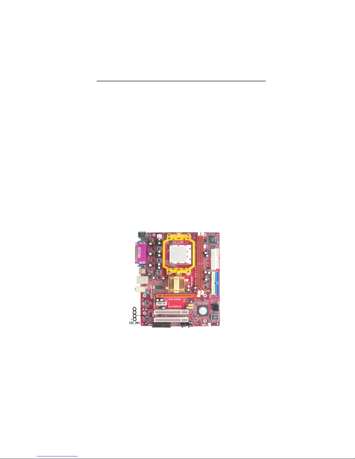
Analog Audio Input Header
If you have installed a CD-ROM drive or DVD-ROM drive, you can connect the
drive audio cable to the onboard sound system.
When you first start up your system, the BIOS should automatically detect your
CD-ROM/DVD drive. If it doesn’t, enter the Setup Utility and configure the CDROM/DVD drive that you have installed. On the motherboard, locate the 4-pin
header CD_IN1.
15
Page 19
Motherboard User’s Guide
Here is a list of CD_IN1 pin assignments.
Pin Signal
1 CD IN L
2GND
3GND
4 CD IN R
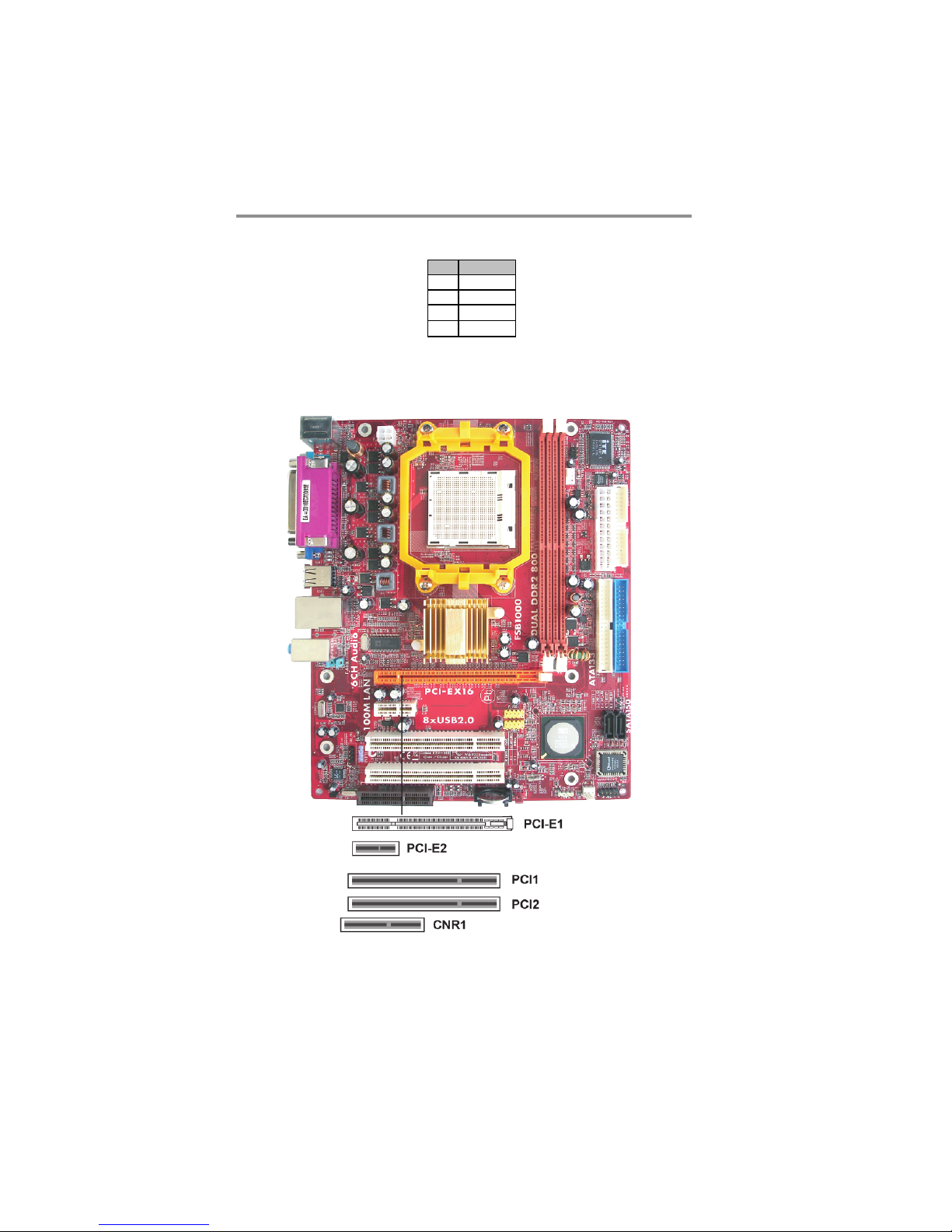
Expansion Slots
This motherboard has one PCI Express x16, one PCI Express x1, one CNR and
two 32-bit PCI slots.
16
Page 20
Chapter 2: Motherboard Installation
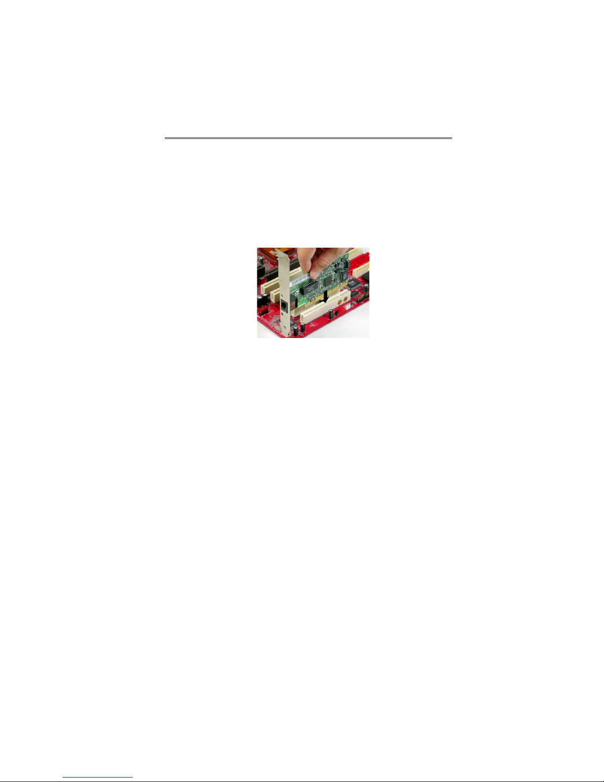
Follow the steps below to install an PCI Express x16/ PCI Express x1/CNR/PCI
expansion card.
1. Locate the PCI Express x16, PCI Express x1, CNR or PCI slots on the
mainboard.
2. Remove the blanking plate of the slot from the system chassis.
3. Install the edge connector of the expansion card into the slot. Ensure the
edge connector is correctly seated in the slot.
4. Secure the metal bracket of the card to the system chassis with a screw.
PCI Express x16 Slot
You can install an external PCI Express graphics card that is fully compliant to the
PCI Express Base Specification revsion 1.0a.
PCI Express x1 Slot
The two PCI Express x1 slots are fully compliant to the PCI Express Base Specification revision 1.0a as well.
CNR Slot
You can install the CNR (Communications and Networking Riser) cards in this slot,
including LAN, Modem, and Audio functions.
PCI Slots
You can install the 32-bit PCI interface expansion cards in the slots.
17
Page 21
Motherboard User’s Guide
Chapter 3 BIOS Setup Utility
Introduction
The BIOS Setup Utility records settings and information of your computer, such
as date and time, the type of hardware installed, and various configuration
settings. Your computer applies the information to initialize all the components
when booting up and basic functions of coordination between system components.
If the Setup Utility configuration is incorrect, it may cause the system to
malfunction. It can even stop your computer booting properly. If it happens,
you can use the clear CMOS jumper to clear the CMOS memory which has
stored the configuration information; or you can hold down the Page Up key
while rebooting your computer. Holding down the Page Up key also clears the
setup information.
You can run the setup utility and manually change the configuration. You might
need to do this to configure some hardware installed in or connected to the
motherboard, such as the CPU, system memory, disk drives, etc.
Running the Setup Utility
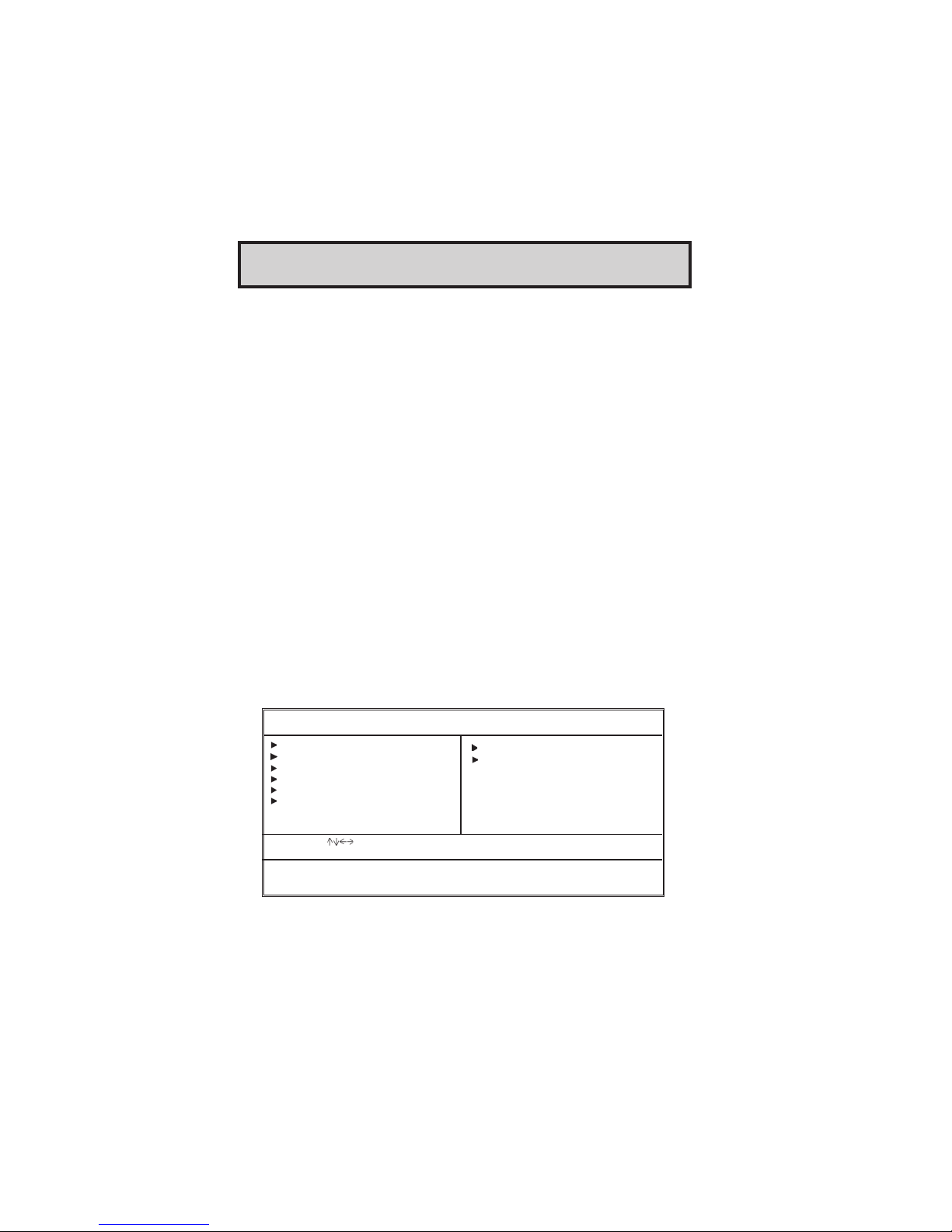
Every time you start your computer, a message appears on the screen before the
operating system loading that prompts you to “Hit <DEL>if you want to run
SETUP”. Whenever you see this message, press the Delete key, and the Main
menu page of the Setup Utility appears on your monitor.
CMOS Setup Utility – Copyright (C) 1985-2005, American Megatrends, Inc
Standard CMOS Setup
Advanced Setup
Features Setup
Power Management Setup
PCI / Plug and Play Setup
BIOS Security Features
: Move Enter: Select +/-/: Value F10: Save Esc: Exit
F1: General Help F9: Optimized Defaults
Standards COMOS setup for changing time, date, hard disk type, etc.
V02.54 (C) 1985-2005, American Megatrends, Inc.
CPU PnP Setup
Hardware Monitor
Load Optimal Settings
Save Changes and Exit
Discard Changes and Exit
You can use cursor arrow keys to highlight anyone of options on the main menu
page. Press Enter to select the highlighted option. Press the Escape key to leave
the setup utility. Press +/-/ to modify the selected field’s values.
18
Page 22
Chapter 3: BIOS Setup Utility
Some options on the main menu page lead to tables of items with installed values
that you can use cursor arrow keys to highlight one item, and press PgUp and
PgDn keys to cycle through alternative values of that item. The other options on
the main menu page lead to dialog boxes requiring your answer OK or Cancel by
selecting the [OK] or [Cancel] key.
If you have already changed the setup utility, press F10 to save those changes
and exit the utility. Press F1 to display a screen describing all key functions.
Press F9 to load optimtimal settings.
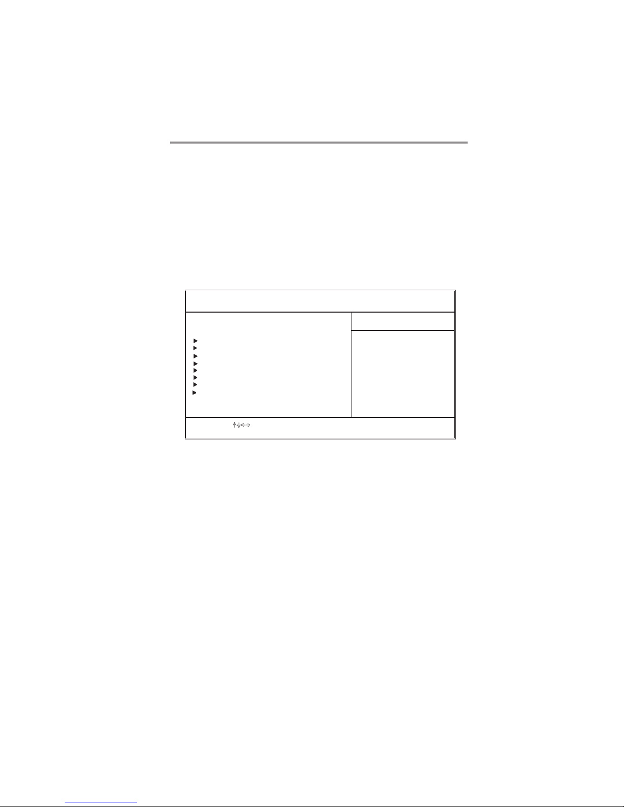
Standard CMOS Setup Page
This page displays a table of items defining basic information of your system.
CMOS Setup Utility – Copyright (C) 1985-2005, American Megatrends, Inc.
System Time 00:47:28
System Date Mon 05/12/2006
Primary IDE Master Hard Disk
Primary IDE Slave Not Detected
Secondary IDE Master Not Detected
Secondary IDE Slave Not Detected
Third IDE Master Not Detected
Third IDE Slave Not Detected
Fourth IDE Master Not Detected
Fourth IDE Slave Not Detected
Floppy A 1.44 MB 31/
Floppy B Disabled
: Move Enter: Select +/-/: Value F10: Save Esc: Exit
F1: General Help F9: Optimized Defaults
Standard CMOS Setup
2
Help Item
User [Enter], [TAB]
or [SHIFT-TAB] to
select a field.
Use [+] or [-] to
configure system Time.
System Date & System Time
These items set up system date and time.
PrimaryIDE Master/Primary Slave/Secondary Master/Secondary Slave/
Third IDE Master/Slave/Fourth IDE Master/Slave
Use these items to configure devices connected to the Primary/Secondary IDE
channels. To configure an IDE hard disk drive, choose Auto. If the Auto setting
fails to find a hard disk drive, set it to User, and then fill in the hard disk
characteristics (Size, Cyls, etc.) manually. If you have a CD-ROM drive, select
the setting CDROM. If you have an ATAPI device with removable media (e.g. a
ZIP drive or an LS-120), select Floptical.
Floppy A/B
These items set up size and capacity of the floppy diskette drive(s) installed in
the system.
19
Page 23
Motherboard User’s Guide
Advanced Setup Page
This page sets up more advanced information about your system. Handle this
page with caution. Any changes can affect the operation of your computer.
CMOS Setup Utility – Copyright (C) 1985-2005, American Megatrends, Inc.
Share Memory
Quick Boot
1st Boot Device
2nd Boot Device
3rd Boot Device
Removable Drives
Try Other Boot Device
Bootup Num-Lock
Boot To OS/2 > 64MB
Aperture Size
Auto Detect DIMM/PCI C1K
Spread Spectrum
: Move Enter: Select +/-/: Value F10: Save Esc: Exit
F1: General Help F9: Optimized Defaults
Advanced Setup
64MB
Enabled
Hard Drive
CD/DVD
Removable Dev.
Press Enter
Yes
On
No
128MB
Enabled
Disabled
Help Item
Allows BIOS to skip
certain tests while
booting. This will
decrease the time
needed to boot the
system.
Quick Boot
If you enable this item, the system starts up more quickly be elimination some
of the power on test routines.
1st Boot Device/2nd Boot Device/3rd Boot Device
Use these items to determine the device order the computer uses to look for an
operating system to load at start-up time.
Try Other Boot Device
If you enable this item, the system will also search for other boot devices if it
fails to find an operating system from the first two locations.
BootUp Num-Lock
This item determines if the Num Lock key is active or inactive at system startup time.
Boot to OS/2 > 64MB
Enable this item if you are booting the OS/2 operating system and you have
more than 64MB of system memory installed.
Aperture Size
This item defines the size of aperture if you use a graphic adapter.
Auto detect DIMM/PCI Clock
When this item is enabled, BIOS will disable the clock signal of free DIMM/PCI
slots.
20
Page 24
Chapter 3: BIOS Setup Utility
Spread Spectrum
If you enable spread spertrum, it can significantly reduce the EMI (ElectroMagnetic interface) generated by the system.
Features Setup Page
This page sets up some parameters for peripheral devices connected to the
system.
CMOS Setup Utility – Copyright (C) 1985-2005, American Megatrends, Inc.
OnBoard Floppy Controller
Serial Port1 Address
OnBoard IR Port
Parallel Port Address
Parallel Port Mode
ECP Mode DMA Channel
Parallel Port IRQ
OnBoard PCI IDE Controller
OnBoard PCI SATA Controller
Onboard AC97 Audio DEVICE
OnBoard AC97 Modem DEVICE
Onboard LAN Device
OnBoard LAN Boot ROM
OnBoard USB Function
USB Function For DOS
: Move Enter: Select +/-/: Value F10: Save Esc: Exit
F1: General Help F9: Optimized Defaults
Features Setup
Enabled
3F8/IRQ4
Disabled
378
ECP
DMA3
IRQ7
Both
IDE
Enabled
Auto
Enabled
Disabled
Enabled
Disabled
Help Item
Allows BIOS to Enable or Disable
Floppy Controller.
OnBoard Floppy Controller
Use this item to enable or disable the onboard floppy disk drive interface.
Serial Port1 Address
Use this item to enable or disable the onboard COM1/2 serial port, and to assign
a port address.
OnBoard IR Port
Use this item to enable or disable the onboard infrared port, and to assign a port
address.
Parallel Port Address
Use this item to enable or disable the onboard Parallel port, and to assign a
port address.
Parallel Port Mode
Use this item to set the parallel port mode. You can select ECP (Extended
Capabilities Port) & EPP (Enhanced Parallel Port).
21
Page 25

Motherboard User’s Guide
ECP Mode DMA Channel
This item assigns a DMA channel to the parallel port.
Parallel Port IRQ
Use this item to assign IRQ to the parallel port.
OnBoard PCI IDE Controller
Use this item to enable or disable both of the onboard Primary and Secondary
IDE channels.
OnBoard PCI S-ATA Controller
Use this item to enable the onboard PCI SATA Controller.
Onboard AC97 Audio DEVICE
This item enables or disables the AC’97 audio chip.
OnBoard AC97 Modem Device
This item enables or disables the onboard AC97 Modem device.
Onboard LAN Device
This item enables or disables the onboard Ethernet LAN.
OnBoard LAN Boot ROM
Enable this item if you want to execute the Boot ROM function of onboard
LAN while starting the system.
OnBoard USB Function
Enable this item if you plan to use the USB ports on this motherboard.
USB Function For DOS
Enable this item if you plan to use the USB ports on this motherboard in a DOS
environment.
22
Page 26
Chapter 3: BIOS Setup Utility
Power Management Setup Page
This page sets some parameters for system power management operation.
CMOS Setup Utility – Copyright (C) 1985-2005, American Megatrends, Inc.
ACPI Aware O/S
Power Management
Suspend mode
Suspend Time Out
Resume On RTC Alarm
Resume On KeyBoard
Keyboard Power On
: Move Enter: Select +/-/: Value F10: Save Esc: Exit
F1: General Help F9: Optimized Defaults
Yes
Enabled
S1
Disabled
Disabled
Disabled
Disabled
Help Item
Enable /Disable
ACPI support for
Operating System.
ENABLE: If OS
supports ACPI.
DISABLE: If OS
does not support
ACPI Aware O/S
This item supports ACPI (Advanced Configuration and Power management
Interface). Use this item to enable or disable the ACPI feature.
ACPI Enhanced Efficiency
It supports ACPI (Advanced Configuraion and Power Management Interface). Use
this item to enable or disable the ACPI feature.
Power Management
Use this item to enable or disable a power management scheme. If you enable
power management, you can use the items below to set the power management
operation. Both APM and ACPI are supported.
Suspend mode
This item selects the status S1 (Stop Clock) or S3 (Suspend to RAM) when the
system enters the power-saving Suspend mode.
Suspend Time Out
This sets the timeout for Suspend mode in minutes. If the time selected passes
without any system activity, the computer will enter power-saving Suspend
mode.
Resume On RTC Alarm
The system can be turned off with a software command. If you enable this item,
the system can automatically resume at a fixed time based on the system’s RTC
(realtime clock). Use the items below this one to set the date and time of the
wake-up alarm. You must use an ATX power supply in order to use this feature.
Resume On KeyBoard
The system can be turned off with a software command. If you enable this item,
system can automatically resume by pressing any keys or power keys on the
keyboard, or typing in the password. You must use an ATX power supply in
order to use this feature.
23
Page 27
Motherboard User’s Guide
LAN/Ring Power On
The system can be turned off with a software command. If you enable this item,
the system can automatically resume if there is an incoming call on the Modem/
Ring, or traffic on the network adapter. You must use an ATX power supply in
order to use this feature.
PCI / Plug and Play Setup Page
This page sets up some parameters for devices installed on the PCI bus and
those utilizing the system plug and play capability.
CMOS Setup Utility – Copyright (C) 1985-2005, American Megatrends, Inc.
Primary Graphics Adapter PCI
Allocate IRQ to PCI VGA Yes
PCI IDE BusMaster Enabled
: Move Enter: Select +/-/: Value F10: Save Esc: Exit
F1: General Help F9: Optimized Defaults
PCI / Plug and Play Setup
Help Item
Options
PCI
PCI Express Card
Primary Graphics Adapter
This item indicates if the primary graphics adapter uses the PCI or the AGP bus.
The default AGP setting still lets the onboard display work and allows the use of
a second display card installed in a PCI slot.
Allocate IRQ to PCI VGA
If this item is enabled, an IRQ will be assigned to the PCI VGA graphics system.
You set this value to No to free up an IRQ.
PCI IDE BusMaster
This item enables or disables the DMA under DOS mode. We recommend you to
leave this item at the default value.
24
Page 28
Chapter 3: BIOS Setup Utility
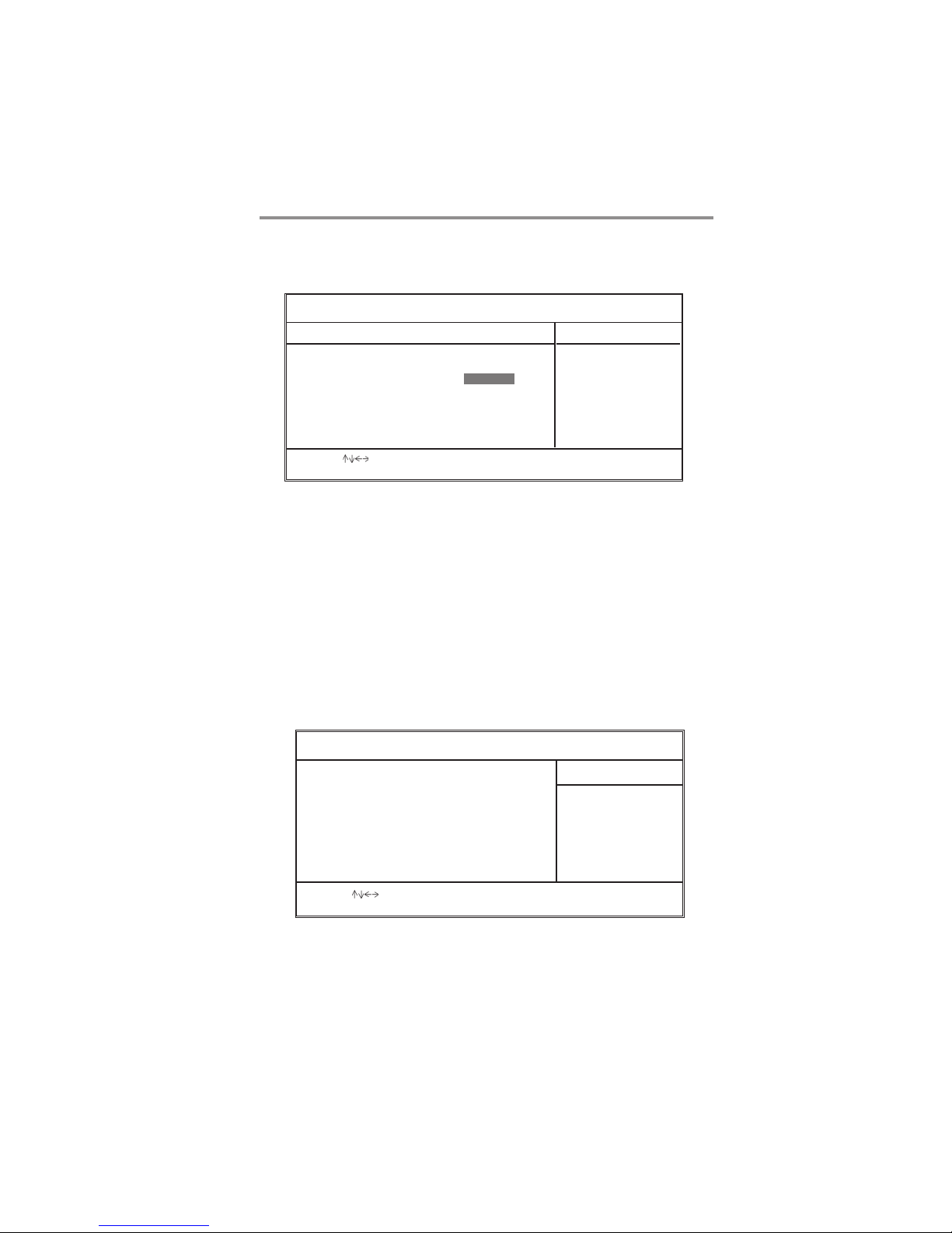
BIOS Security Features Setup Page
This page helps you install or change a password.
CMOS Setup Utility – Copyright (C) 1985-2005, American Megatrends, Inc.
Security Settings
Supervisor Password : Not Installed
Change Supervisor Password Press Enter
: Move Enter: Select +/-/: Value F10: Save Esc: Exit
F1: General Help F9: Optimized Defaults
BIOS Security Features
Help Item
Install or Change the
password.
Supervisor Password
This item indicates whether a supervisor password has been set. If the password
has been installed, Installed displays. If not, Not Installed displays.
Change Supervisor Password
You can select this option and press <Enter> to access the sub menu. You can
use the sub menu to change the supervisor password.
CPU PnP Setup Page
This page helps you manually configure the mainboard for the CPU. The system
will automatically detect the type of installed CPU and make the appropriate
adjustments to the items on this page.
CMOS Setup Utility – Copyright (C) 1985-2005, American Megatrends, Inc.
CPU Type : AMD Athlon (tm) 64 Processor 3500+
CPU OVERCLOCK : 200
DIMM Voltage Adjust Function Normal
CPU Voltage Control Disabled
CPU PnP Setup
Help Item
CPU Freq Over Clock 200
to 255 MHz
: Move Enter: Select +/-/: Value F10: Save Esc: Exit
F1: General Help F9: Optimized Defaults
25
Page 29
Motherboard User’s Guide
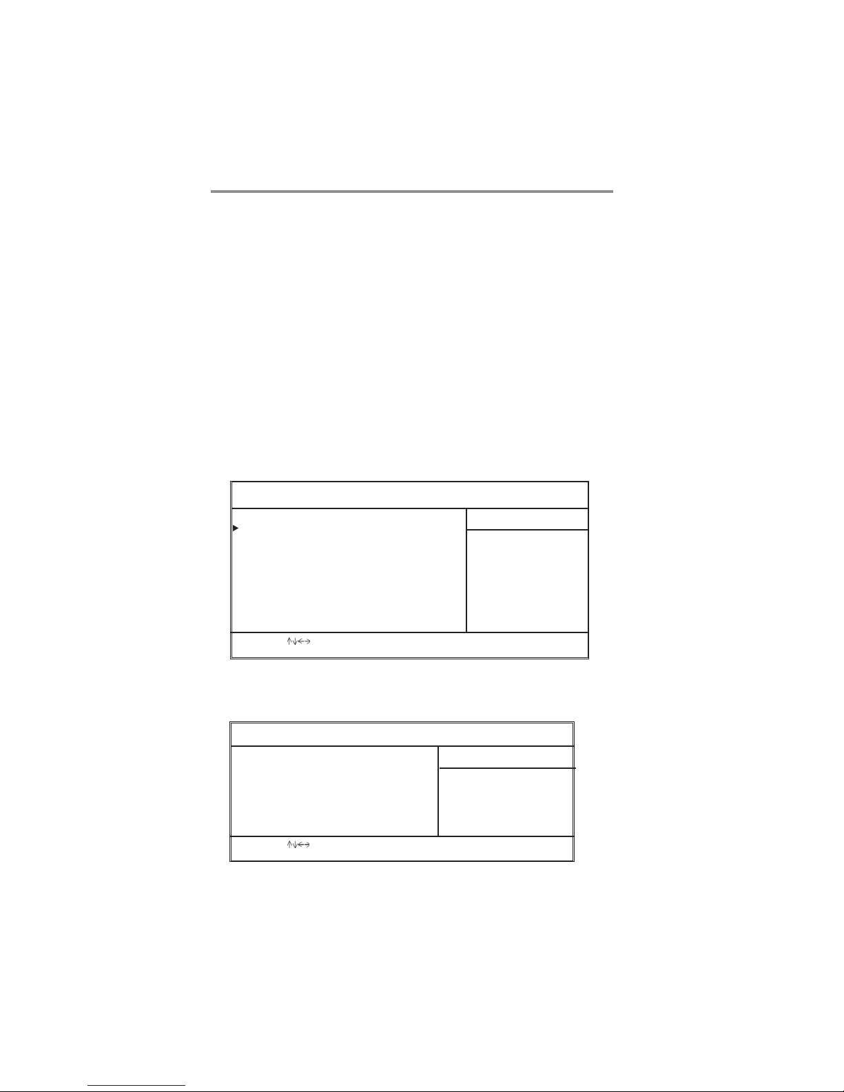
CPU Type
This item shows the type of the CPU installed in your system.
CPU OVERCLOCK
This item decides the CPU over-clocking function installed in your system. If
the over-clocking fails, please turn off the system power. And then, hold the
PageUp key (similar to the Clear CMOS function) and turn on the power, the
BIOS will recover the safe default.
DIMM Voltage Adjust Function
This item enables or disables users to adjust DIMM voltage.
CPU Voltage Control
This item enables or disables users to control CPU voltage.
Hardware Monitor Page
This page sets up some parameters for the hardware monitoring function of this
motherboard.
CMOS Setup Utility – Copyright (C) 1985-2005, American Megatrends, Inc.
*** System Hardware Monitor***
Smart Fan Function Press Enter
Vcore :1.360V
NB Vcore : 1.808V
VDIMM : 1.824V
CPU FAN Speed :5720 RPM
System Fan Speed :0 RPM
CPU Temperature :27°C/80°F
System Temperature :21°C/69°F
Hardware Monitor Setup
Help Item
: Move Enter: Select +/-/: Value F10: Save Esc: Exit
F1: General Help F9: Optimized Defaults
XSmart Fan Function (Press Enter)
Scroll to this item and press <Enter> to view the following screen:
CMOS Setup Utility – Copyright (C) 1985-2005, American Megatrends, Inc.
CPU SMART FAN Setting Disabled
: Move Enter: Select +/-/: Value F10: Save Esc: Exit
F1: General Help F9: Optimized Defaults
Smart Fan Function
Help Item
Fan configuration mode setting
26
Page 30

Chapter 3: BIOS Setup Utility
FANs & Voltage Measurements
These items indicate cooling fan speeds in RPM and the various system voltage
measurements.
CPU/SYS FAN Speed
This item displays CPU/ system speed measurement.
CPU/System Temperature
This item displays CPU/ system temperature measurements.
Load Optimal Defaults
This option opens a dialog box to ask if you are sure to install optimized
defaults or not. You select [OK], and then <Enter>, the Setup Utility loads all
default values; or select [Cancel], and then <Enter>, the Setup Utility does not
load default values.
Note: It is highly recommend that users enter this option to load optimal default
values for accessing the best performance.
Save Changes and Exit
Highlight this item and press <Enter> to save the changes that you have made in
the Setup Utility configuration. When the Save Changes and Exit dialog box
appears, select [OK] to save and exit, or [Cancel] to return to the main menu.
Discard Changes and Exit
Highlight this item and press <Enter> to discard any changes that you have made
in the Setup Utility and exit the Setup Utility. When the Discard Changes and
Exit dialog box appears, select [OK] to discard changes and exit, or [Cancel] to
return to the main menu.
Note: If you have made settings that you do not want to save, use the
“Discard Changes and Exit” item and select [OK] to discard any
changes you have made.
27
Page 31
Motherboard User’s Guide
Chapter 4 Software & Applications
Introduction
This chapter describes the contents of the support CD-ROM that comes with the
motherboard package.
The support CD-ROM contains all useful software, necessary drivers and utility
programs to properly run our products. More program information is available in
a README file, located in the same directory as the software.
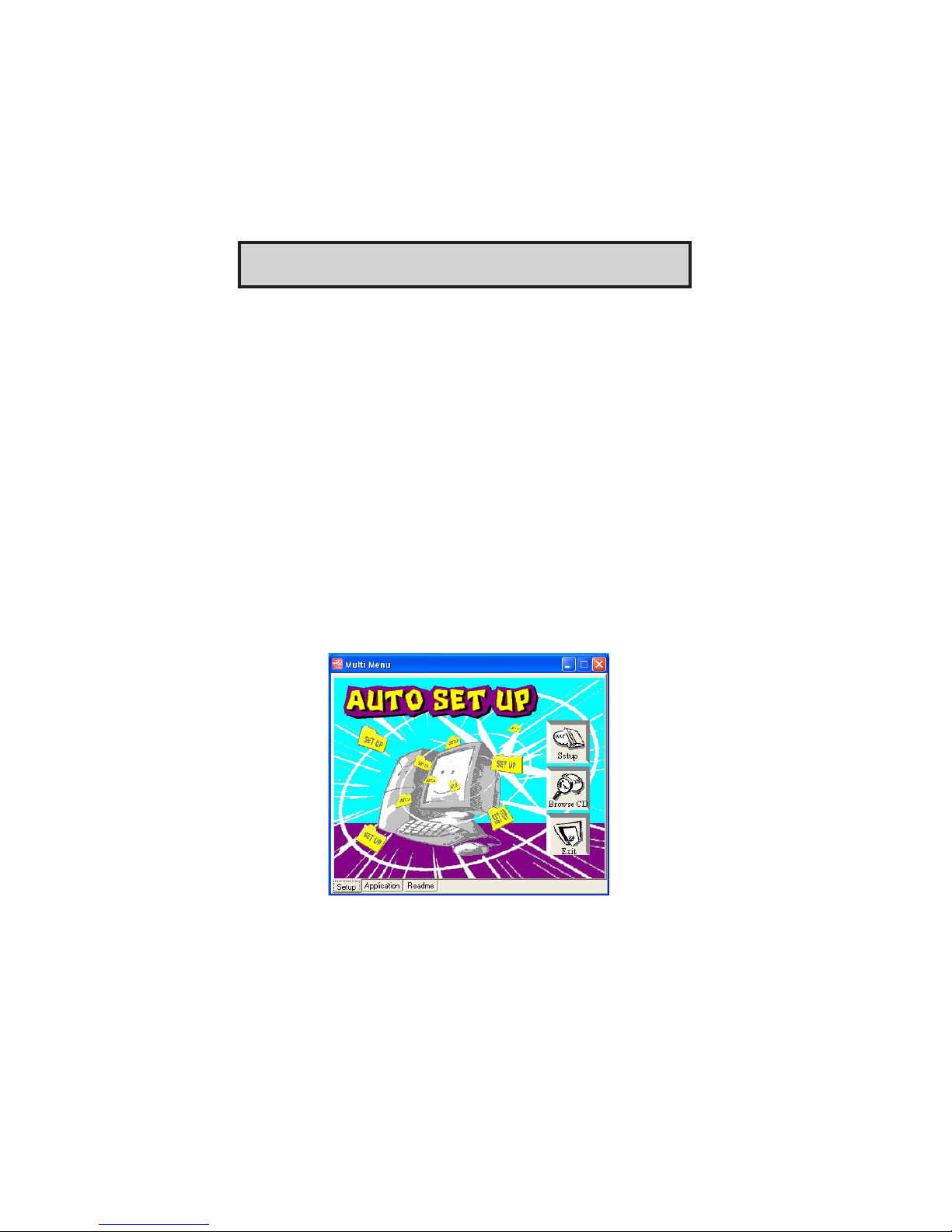
To run the support CD, simply insert the CD into your CD-ROM drive. An Auto
Setup screen automatically pops out, and then you can go on the auto-installing or
manual installation depending on your operating system.
If your operating system is Windows 2000/XP, it will automatically install all the
drivers and utilities for your motherboard.
Installing Support Software
1 Insert the support CD-ROM disc in the CD-ROM drive.
2 When you insert the CD-ROM disc in the system CD-ROM drive,
the CD automatically displays an Auto Setup screen.
3 The screen displays three buttons of Setup, Browse CD and Exit on
the right side, and three others Setup, Application and ReadMe at
the bottom. Please see the following illustration.
The Setup button runs the software auto-installing program as explained in next
section.
The Browse CD button is a standard Windows command that you can check the
28
Page 32
Chapter 4: Software & Applications
contents of the disc with the Windows file browsing interface.
The Exit button closes the Auto Setup window. To run the program again, reinsert
the CD-ROM disc in the drive; or click the CD-ROM driver from the Windows
Explorer, and click the Setup icon.
The Application button brings up a software menu. It shows the bundled software
that this mainboard supports.
The ReadMe brings you to the Install Path where you can find out path names of
software driver.
Auto-Installing under Windows 98/2000/XP
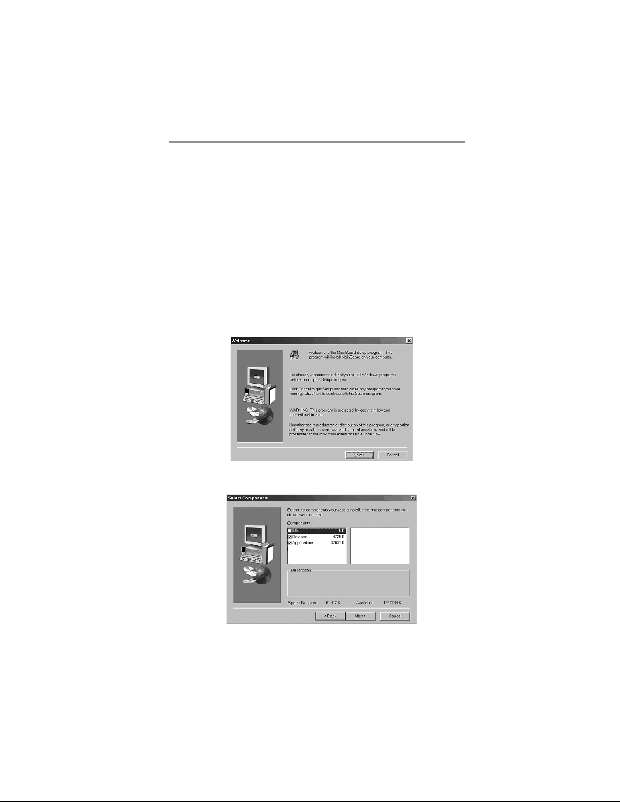
If you are under Windows 98/2000/XP, please click the Setup button to run the
software auto-installing program while the Auto Setup screen pops out after
inserting the support CD-ROM:
1 The installation program loads and displays the following screen.
Click the Next button.
2 Select the items that you want to setup by clicking on it (the default
options are recommended). Click the Next button to proceed.
29
Page 33

Motherboard User’s Guide
3 The support software will automatically install.
Once any of the installation procedures start, software is automatically installed in
sequence. You need to follow the onscreen instructions, confirm commands and
allow the computer to restart as few times as needed to complete installing whatever software you selected. When the process is finished, all the support software
will be installed and start working.
Bundled Software Installation
All bundled software available on the CD-ROM is for users’ convenience. You can
install bundled software as follows:
1 Click the Application button while the Auto Setup screen pops out
after inserting the support CD-ROM.
2 A software menu appears. Click the software you want to install.
3 Follow onscreen instructions to install the software program step by
step until finished.
AMI/AWARD Flash Utility
This utility lets you erase the system BIOS stored on a Flash Memory chip on the
motherboard, and lets you copy an updated version of the BIOS to the chip.
Proceed with caution when using this program. If you erase the current BIOS and
fail to write a new BIOS, or write a new BIOS that is incorrect, your system will
malfunction. Refer to Chapter 3, Using BIOS for more information.
WinFlash Utility
The WinFlash utility is a Windows version of the DOS BIOS flash writer utility.
The utility enables you to flash the system BIOS stored on a Flash Memory chip
on the motherboard while in a Windows environment. This utility is currently
available for WINXP\2000. To install the WinFlash utility, run AFUWIN.EXE
(AMI) or WINFLASH.EXE(Award) from the following directory:
\UTILITY\AMIFLASH or AWDFLASH.
30
 Loading...