


Model 2508-01A/TCS-2A
Reaction Torque Sensor
Installation and Operating Manual
For assistance with the operation of this product,
contact PCB Piezotronics, Inc.
Toll-free: 800-828-8840
24-hour SensorLine: 716-684-0001
Fax: 716-684-0987
E-mail: info@pcb.com
Web: www.pcb.com

Service, Repair, and Return
Policies and Instructions
The information contained in this document supersedes all similar information that
may be found elsewhere in this manual.
Service – Due to the sophisticated
nature of the sensors and associated
instrumentation provided by PCB
Piezotronics, user servicing or repair is
not recommended and, if attempted,
may void the factory warranty. Routine
maintenance, such as the cleaning of
electrical connectors, housings, and
mounting surfaces with solutions and
techniques that will not harm the
physical material of construction, is
acceptable. Caution should be observed
to ensure that liquids are not permitted
to migrate into devices that are not
hermetically sealed. Such devices
should only be wiped with a dampened
cloth and never submerged or have
liquids poured upon them.
Repair – In the event that equipment
becomes damaged or ceases to
operate, arrangements should be made
to return the equipment to PCB
Piezotronics for repair. User servicing or
repair is not recommended and, if
attempted, may void the factory
warranty.
Calibration – Routine calibration of
sensors and associated instrumentation
is recommended as this helps build
confidence in measurement accuracy
and acquired data. Equipment
calibration cycles are typically
established by the users own quality
regimen. When in doubt about a
calibration cycle, a good “rule of thumb”
is to recalibrate on an annual basis. It is
also good practice to recalibrate after
exposure to any severe temperature
extreme, shock, load, or other
environmental influence, or prior to any
critical test.
PCB Piezotronics maintains an ISO9001 certified metrology laboratory and
offers calibration services, which are
accredited by A2LA to ISO/IEC 17025,
with full traceability to SI through
N.I.S.T. In addition to the normally
supplied calibration, special testing is
also available, such as: sensitivity at
elevated or cryogenic temperatures,
phase response, extended high or low
frequency response, extended range,
leak testing, hydrostatic pressure
testing, and others. For information on
standard recalibration services or
special testing, contact your local PCB
Piezotronics distributor, sales
representative, or factory customer
service representative.
Returning Equipment – Following
these procedures will ensure that your
returned materials are handled in the
most expedient manner. Before
returning any equipment to PCB
Piezotronics, contact your local
distributor, sales representative, or
factory customer service representative
to obtain a Return Warranty, Service,
Repair, and Return Policies and
Instructions Materials Authorization
(RMA) Number. This RMA number
should be clearly marked on the outside
of all package(s) and on the packing

list(s) accompanying the shipment. A
detailed account of the nature of the
problem(s) being experienced with the
equipment should also be included
inside the package(s) containing any
returned materials.
A Purchase Order, included with the
returned materials, will expedite the
turn-around of serviced equipment. It is
recommended to include authorization
on the Purchase Order for PCB to
proceed with any repairs, as long as
they do not exceed 50% of the
replacement cost of the returned
item(s). PCB will provide a price
quotation or replacement
recommendation for any item whose
repair costs would exceed 50% of
replacement cost, or any item that is not
economically feasible to repair. For
routine calibration services, the
Purchase Order should include
authorization to proceed and return at
current pricing, which can be obtained
from a factory customer service
representative.
Contact Information – International
customers should direct all inquiries to
their local distributor or sales office. A
complete list of distributors and offices
can be found at www.pcb.com.
Customers within the United States may
contact their local sales representative
or a factory customer service
representative. A complete list of sales
representatives can be found at
www.pcb.com. Toll-free telephone
numbers for a factory customer service
representative, in the division
responsible for this product, can be
found on the title page at the front of this
manual. Our ship to address and
general contact numbers are:
PCB Piezotronics, Inc.
3425 Walden Ave.
Depew, NY14043 USA
Toll-free: (800) 828-8840
24-hour SensorLineSM: (716) 684-0001
Website: www.pcb.com
E-mail: info@pcb.com

PCB工业监视和测量设备 - 中国RoHS2公布表
PCB Industrial Monitoring and Measuring Equipment - China RoHS 2 Disclosure Table
部件名称
有害物质
铅 (Pb)
汞
(Hg)
镉
(Cd)
六价铬 (Cr(VI))
多溴联苯 (PBB)
多溴二苯醚 (PBDE)
住房
O O O
O O O
PCB板
X O O
O O O
电气连接器
O O O
O O O
压电晶体
X O O
O O O
环氧
O O O
O O O
铁氟龙
O O O
O O O
电子
O O O
O O O
厚膜基板
O O X
O O O
电线
O O O
O O O
电缆
X O O
O O O
塑料
O O O
O O O
焊接
X O O
O O O
铜合金/黄铜
X O O
O O O
本表格依据 SJ/T 11364 的规定编制。
O: 表示该有害物质在该部件所有均质材料中的含量均在 GB/T 26572 规定的限量要求以下。
X: 表示该有害物质至少在该部件的某一均质材料中的含量超出 GB/T 26572 规定的限量要求。
铅是欧洲RoHS指令2011/65/ EU附件三和附件四目前由于允许的豁免。
CHINA RoHS COMPLIANCE

Component Name
Hazardous Substances
Lead
(Pb)
Mercury
(Hg)
Cadmium
(Cd)
Chromium VI
Compounds
(Cr(VI))
Polybrominated
Biphenyls
(PBB)
Polybrominated
Diphenyl
Ethers (PBDE)
Housing O O O O O O
PCB Board
X O O O O
O
Electrical
Connectors
O O O O O
O
Piezoelectric
Crystals
X O O O O
O
Epoxy O O O O O O
Teflon O O O O O O
Electronics
O O O O O
O
Thick Film
Substrate
O O X O O
O
Wires O O O O O O
Cables X O O O O O
Plastic O O O O O O
Solder X O O O O O
Copper Alloy/Brass
X O O O O
O
This table is prepared in accordance with the provisions of SJ/T 11364.
O: Indicates that said hazardous substance contained in all of the homogeneous materials for this part is below the limit
requirement of GB/T 26572.
X: Indicates that said hazardous substance contained in at least one of the homogeneous materials for this part is above
the limit requirement of GB/T 26572.
Lead is present due to allowed exemption in Annex III or Annex IV of the European RoHS Directive 2011/65/EU.
DOCUMENT NUMBER: 21354
DOCUMENT REVISION: D
ECN: 46162

REACTION TORQUE SENSOR OPERATION MANUAL
TABLE OF CONTENTS
Section Page
1.0 Introduction 2
2.0 Safety Information 3
3.0 Mechanical Installation 3
4.0 Electrical Installation 4
5.0 Polarity 4
6.0 Shunt Calibration 4
7.0 Operation 5
8.0 Troubleshooting 6
9.0 Maintenance 6
LIST OF ILLUSTRATIONS
Figure Page
1. Flange Mount Reaction Torque Sensor 2
2. Wheatstone Bridge Circuit 2
3. Western Regional Strain Gage Committee Wiring Code 2
4. Axis and Sense Nomenclature 3
5. Reaction Torque Sensor Configurations 3
6. Shunt Resistor Locations 4
7. Reaction Torque Sensor System Configurations 5
1
MANUAL NUMBER: 18622
MANUAL REVISION: A
ECN NUMBER: 17765
VOLTAGE IN
VOLTAGE OUT
REACTION TORQUE SENSOR OPERATION MANUAL
2
1.0 INTRODUCTION
Reaction torque sensors manufactured by the ForceTorque Division of PCB are strain gage based
measuring instruments suitable for a wide range of
torque measurement applications. They are rigid
structures with no moving parts and are typically
mounted in a fixed position. Their output signal
varies proportionally to an applied torsional force.
Capacities range from 5 to 500k in-lb (0.56 to 56.5k
N-m).
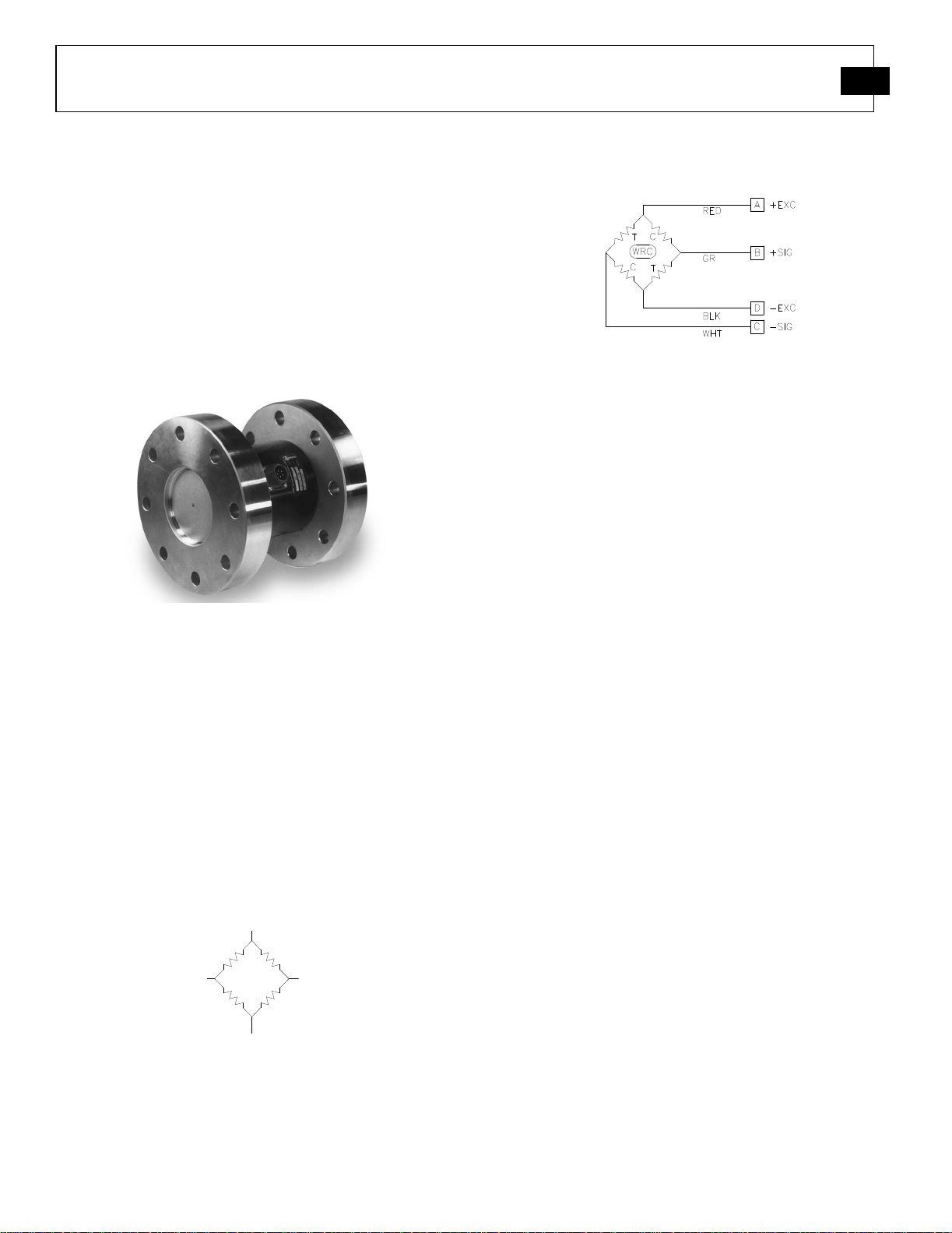
Figure 1 – Flange Mount Reaction Torque Sensor
Due to the fact that these sensors do not utilize
bearings, slip rings, or any other rotating elements,
their installation and use can be very cost effective.
Reaction torque sensors are particularly useful in
applications where the introduction of a rotating
mass between the driver and driven is undesirable.
All models utilize strain gages configured into a
Wheatstone Bridge Circuit to produce the primary
sensing element. The four-arm Wheatstone Bridge
configuration is shown below in Figure 2.
SIGNAL OUT
SIGNAL IN
Figure 2 - Wheatstone Bridge Circuit
Most PCB reaction torque sensors follow a wiring
code established by the Western Regional Strain
Gage Committee as revised in May 1960. The
wiring code is as follows:
Figure 3 - Western Regional Strain Gage Committee
Wiring Code
Refer to the wiring drawing included with this
manual for specific wiring of the supplied torque
sensor.
The gages are bonded to the sensor’s structure.
Typically, a regulated DC or AC excitation is
applied between A and D of the bridge. When
torque is applied to the sensor, the Wheatstone
Bridge becomes unbalanced, causing an output
voltage between B and C which is proportional to
the applied torque. The magnitude of the output
voltage corresponds to the torsional deflection of
the sensor structure and therefore the applied torque.
This configuration allows for temperature and
pressure compensation, as well as cancellation of
signals caused by forces not directly applied to the
axis of the applied load. Output is typically
expressed in units of millivolt per volt of excitation.
Optional signal conditioners are available from
PCB. A signal conditioner may have analog voltage
output, current output, or digital output. Digital
display signal conditioners are also available.
Axis Definition
PCB force products comply with the Axis and
Sense Definitions of NAS-938 (National Aerospace
Standard-Machine Axis and Motion) nomenclature
and recommendations of the Western Regional
Strain Gage committee. These axes are defined in
terms of a "Right Handed" orthogonal coordinate
system as show below. A (+) sign indicates force in
a direction which produces a (+) signal voltage and
generally defines a clockwise torque.

REACTION TORQUE SENSOR OPERATION MANUAL
3
Figure 4 - Axis and Sense Nomenclature for PCB Reaction
Torque Sensors
The principal axis of a transducer is normally the
MZ axis. The MZ axis will also be the axis of radial
symmetry or axis of rotation. In the event there is no
clearly defined axis, the following preference
system will be used z,x,y.
2.0 SAFETY INFORMATION
Failure of the sensor structure or fasteners used in
its installation may cause personal injury and
equipment damage. To prevent structure failure,
review the extraneous load limits listed on the
specification sheet supplied with this manual.
Extraneous load limits are extraneous side force,
thrust and bending moment that may be applied
without electrical or mechanical damage to the
torque sensor. Do not exceed moment (W x S) or
shear (W) whichever attained first. Measurement
inaccuracy and structure damage may result. Install
the sensor in a manner that minimizes these loads.
In addition, review data from manufacturers of
fixtures and fasteners used in the sensors
installation to determine if failure might occur due
to these loads.
3.0 MECHANICAL INSTALLATION
Refer to the outline drawing supplied with this
manual for specific outline dimensions and
installation details for your particular model. The
specification is also included to provide details of
the sensor’s characteristic properties.
Shown below are some of the standard reaction
torque sensor configurations offered by the
Force/Torque Division.
Figure 5 – Reaction Torque Sensor Configurations

REACTION TORQUE SENSOR OPERATION MANUAL
4
4.0 ELECTRICAL INSTALLATION
For proper electrical connections, refer to the
installation drawing for the torque sensor, and the
wiring drawing for the signal conditioner used.
Construct the interconnect cable from high-quality
shielded instrumentation cable. Various cable
assemblies are available through PCB.
Connect one end of the cable to the sensor
connector and the other end to the signal
conditioner. Make sure to tighten the cable
connector to the sensor. For installation in dirty,
humid, or rugged environments, it is suggested that
the connection be shielded against dust or moisture
with shrink tubing or other protective material.
Strain relieving the cable/sensor connection can also
prolong cable life. Mounting cables to a test
structure with tape, clamps, or adhesives minimizes
cable whip.
5.0 POLARITY
Clockwise torque upon standard PCB reaction
torque sensors produces a positive-going voltage
output. Counter-clockwise torque produces a
negative-going voltage output.
6.0 SHUNT CALIBRATION
Shunt calibration is the known, electrical,
unbalancing of a strain gage bridge by means of a
fixed resistor that is placed, or “shunted”, across
one leg of the bridge. The “Wheatstone Bridge”
utilized by PCB reaction torque sensors are typically
calibrated using the shunt calibration technique.
Shunt calibration is a method of periodically
checking the gain or span of a signal conditioner,
which is used in conjunction with a strain gage
based transducer, without exposing the transducer to
known, traceable, physical input values. If required,
adjustments can then be made to the signal
conditioner to insure accurate measurement results.
The strain gage bridge is “in balance” when the host
mechanical structure is unloaded and unstressed.
As the host structure (diaphragm, bending beam,
shear beam, column, etc.) is loaded or stressed, the
Wheatstone Bridge becomes unbalanced, resulting
in an output signal that is proportional to the applied
load.
Shunt calibration simulates the mechanical input to
a transducer by unbalancing the bridge with a fixed
resistor placed across, or in parallel with, one leg of
the bridge. For tension shunt calibration, or +CAL,
the shunt resistor (Rst) is shunted across the
+Excitation (A) and +Signal (B) leg of the bridge.
For compression shunt calibration, or –CAL, the
shunt resistor (Rsc) is shunted across the -Excitation
(D) and +Signal (B) leg of the bridge. Refer to
Figure 6 for shunt resistor locations in the
Wheatstone Bridge circuit.
Figure 6 - Shunt Resistor Locations
Shunt Calibration Procedure
1. Connect the transducer to an appropriate strain
gage signal conditioner and allow adequate time
for the system to stabilize.
2. Apply a full-scale, N.I.S.T. traceable,
mechanical input (or torque) to the transducer.
3. Adjust the signal conditioner’s gain or span
controls, as required, to obtain a full-scale
electrical output signal, and/or numeric display
that represents the applied, mechanical input
quantity.
4. Remove the mechanical input (or torque).
5. Place the shunt calibration resistor across an
appropriate leg of the Wheatstone Bridge as
discussed above.

REACTION TORQUE SENSOR OPERATION MANUAL
5
6. Record the value of the signal conditioner’s
output signal and/or numeric display. This
value is the shunt calibration value, or
equivalent torque.
7. It is important to note that the shunt calibration
used. This value, and the particular resistor, are
now matched to the transducer and form a basis
of the transferable shunt calibration.
value is specific for the particular shunt resistor
Recalculating Shunt Calibration Value
The shunt calibration resistor value and the resulting transducer output can be recalculated using the following
formula:
Supplied Transducer Output
= New Resistor Value
New Transducer Output Supplied Resistor Value
Shunt calibration is accepted throughout the industry as a means of periodic calibration of a signal conditioner
and transducer between calibrations of known, applied, traceable, mechanical, input values. Consequently, most
all strain gage transducer manufacturers collect and supply shunt calibration data, along with a shunt calibration
resistor, as a standard feature.
7.0 OPERATION
Figure 7 – Reaction Torque Sensor System Configurations
Typical Reaction Torque Sensor System Configurations
Operation requires the connection of the sensor to a signal conditioner, then to a readout device (if signal
conditioner does not have a display). Strain gage signal conditioners and cable assemblies are available from
PCB.
Operation with a Signal Conditioner
The signal conditioner span and zero must be set before the torque sensor system can be used. The span can be
set using dead weights or the shunt calibration value. Refer to the shunt calibration information in this manual,
and the signal conditioner instruction manual, for proper set-up information.

REACTION TORQUE SENSOR OPERATION MANUAL
8.0 TROUBLESHOOTING
No output
No power
Loose or dirty connections
Circuit opens or shorts
Faulty or improper wiring
No load applied
Erratic or Improper Readings
Excitation voltage drift
Electrical noise
Loose fixturing
Circuit opens or shorts
Improper torque applied
Cable too long
Blinking Display
Overload condition
Open circuit
Zero Balance
Torque applied to sensor
Overloaded or side-loaded sensor
Open circuit
Improper electrical connections
Zero Shift
Fixture preload
Faulty or improper wiring
Improper tare
Zero Drift
Unconditioned power supply
Circuit opens or shorts
Loose wiring
RFI/EMI interface
Temperature change
Damaged or Deformed Equipment
Improper use
Often overlooked by the customer, is the error due
to the presence of non-measured forces and bending
moments. Even Though the Single Axis of
6
Measurement sensors are designed and built to
withstand these non-measured forces and bending
moments (extraneous loads), the errors due to them
are present. PCB engineers can design the set-up to
eliminate or minimize these extraneous loads.
However, if these extraneous loads are present, the
errors due to them should be considered. Due to
cost restraints, the Force/Torque Division, as with
its competition, does not typically measure or
compensate for errors due to extraneous loads. If
the presences of these extraneous loads are known,
the user should request the transducer manufacturer
to run a special test, at extra cost, to define and
quantify the extraneous load errors. These errors are
defined as cross-talk errors.
Error Analysis
The Force/Torque Division typically supplies
accuracy information on its products in the form of
individual errors (see specification sheet). They are:
Non-Linearity, Hysteresis, Non-Repeatability,
Effect of Temperature on Zero, and Effect of
Temperature on Output.
The customer can combine these individual errors to
establish the maximum possible error for the
measurement or just examine the applicable
individual error. If the temperature remains stable
during the test, temperature related errors may be
ignored. If the sensor is used for increasing load
measurement only, ignore the Hysteresis error. If
the load measurement is near the full capacity, the
linearity error can be ignored. If the capability exists
to correct the data through linearization-fit or a
look-up-table, the error in the measurement can be
minimized. A sophisticated user can get rid of all
the errors except for the non-repeatability error in
the measurement.
9.0 MAINTENANCE
Routine maintenance, such as cleaning of electrical
connectors, housings, and mounting surfaces with
solutions and techniques that will not harm the
physical material of construction is acceptable.

REACTION TORQUE SENSOR OPERATION MANUAL
7
Caution should be observed to insure that liquids
are not permitted to migrate into devices that are not
hermetically sealed. Such devices should only be
wiped with a damp cloth and never submerged or
have liquids poured on them.
Model Number
e
I
l
l
.
[4]
.
2508-01A
Performanc
Measurement Range(Full Scale Capacity) 50 lbf-in 5.65 Nm
Sensitivity(output at rated capacity) 2 mV/V 2 mV/V
Non-Linearity ≤ 0.10 % FS ≤ 0.10 % FS
Hysteresis ≤ 0.10 % FS ≤ 0.10 % FS
Non-Repeatability ≤ 0.02 % FS ≤ 0.02 % FS
Resonant Frequency 380 Hz 380 Hz
Maximum Torque 75 lbf-in 8.47 Nm
ENGLISH S
REACTION TORQUE SENSOR
Environmenta
Overload Limit(Axial Thrust) 200 lbf 890 N
Overload Limit(Overhung Moment) 50 lbf-in 5.65 Nm
Overload Limit(Shear) 13 lbf 57.8 N
Temperature Range(Operating) -65 to +200 °F -54 to +93 °C
Temperature Range(Compensated) +70 to +170 °F +21 to +77 °C
Temperature Effect on Output(Maximum) ± 0.002 %Reading/°F ± 0.0036 %Reading/°C
Temperature Effect on Zero Balance(Maximum) ± 0.002 %FS/°F ± 0.0036 %FS/°C
Electrical
Bridge Resistance 700 Ohm 700 Ohm
Excitation Voltage(Recommended) 10 VDC 10 VDC
Insulation Resistance 5 GOhm 5 GOhm
Zero Balance ≤ 1.0 %RO ≤ 1.0 %RO
Output Polarity cw+ cw+
Physica
Size (Diameter x Length) 2.0 in x 3.0 in 50.8 mm x 76.2 mm
Weight 2.0 lb 908 g
Mounting Flange (#10-24 Bolts) Flange (No Metric Equivalent)
Torsional Stiffness 2350 lbf-in/radian 265.5 N-m/radian
Sensing Element Strain Gage Strain Gage
Housing Material(Sensor) Anodized Aluminum Anodized Aluminum
Electrical Connector PT02E-10-6P PT02E-10-6P
All specifications are at room temperature unless otherwise specified.
In the interest of constant product improvement, we reserve the right to change specifications without notice.
Revision: G
ECN #: 47636
OPTIONAL VERSIONS
Optional versions have identical specifications and accessories as listed for the standard model
[5][4]
[4]
[4]
[4]
NOTES:
[2]
[1] Calibrated at 10 VDC, usable 5 to 20 VDC or VAC RMS
[2]
[2] Singularly applied, i.e. no other extraneous loads.
[2]
[3] Over compensated operating temperature range.
FS - Full Scale
[5] Nominal.
[3]
[6] See Drawing 32786 for Complete Dimensions
[4][3]
except where noted below. More than one option may be used.
SUPPLIED ACCESSORIES:
Model 181-012A PT06A-10-6S(SR) (1)
[1]
Entered: LK Engineer: PE Sales: KH Approved: JSD Spec Number:
Date: 2/22/2018 Date: 2/22/2018 Date: 2/22/2018Date: 2/22/2018
[6]
PCB Load & Torque
A Division of PCB Piezotronics
24350 Indoplex Circle
Farmington Hills, MI 48335
UNITED STATES
Phone: 866-684-7107
E-Mail: LTSales@pcb.com
Web site: www.pcb.com/LoadAndTorque
18531

PCB Load & Torque Inc. claims proprietary rights in
the information disclosed hereon. Neither it nor any
reproduction thereof will be disclosed to others without
the written consent of PCB Load and Torque Inc.
6
4
3
2
REVISIONS
REV DESCRIPTION ECO
D
UPDATED GD&T SPECS - 05.02.16, PTE
1
45413
8
7
2
3
1.00 [25.4]
B B
o
PT02E-10-6P RECEPTACLE
PIN A +EXC.
PIN B +SIG.
PIN C -SIG.
PIN D -EXC.
PIN E N/C
PIN F N/C
.253
6.43
.251
.001 A
.001 B
[ ]
6.38
2X
i
b
1.44 [36.6]
1.91 [48.4]
A
1.627
Ø
1.625
41.33
[ ]
41.28
1.627
1.625
41.33
[ ]
41.28
2.00 [50.8]Ø
45°
n
1.250 [31.75]2X B.C.
.14 [3.6]2X
r
.001 A
.31 [7.9] 2.38 [60.5]
10-24 UNC - 2B x .384X
EQUALLY SPACED
BOTH ENDS
n
.005 A
j
A A
b
B
.001 A
3.00 [76.2]
f
.001 B
UNLESS OTHERWISE SPECIFIED TOLERANCES ARE:
DIMENSIONS IN INCHES
DECIMALS XX ±.01
ANGLES
4
3
XXX ±.005
`
.5 DEGREES
FILLETS AND RADII
.015 MAX
DIMENSIONS IN MILLIMETERS
[ IN BRACKETS ]
DECIMALS X ± 0.3
ANGLES
XX ± 0.13
`
.5 DEGREES
FILLETS AND RADII
0.38 MAX
2
DRAWN CHECKED ENGINEER
01.20.12
MDF
TITLE
ECB
01.26.12
OUTLINE DRAWING
2508 SERIES
TORQUE SENSOR
PTE
1/20/12
24350 Indoplex Circ le, Farmington Hills,MI 48335
(716) 684-0001 E-M AIL: ltinfo@pcbloadtorque.com
DWG. NO.
32786
SCALE: SHEET
1
1 OF 1FULL
 Loading...