

Page 1
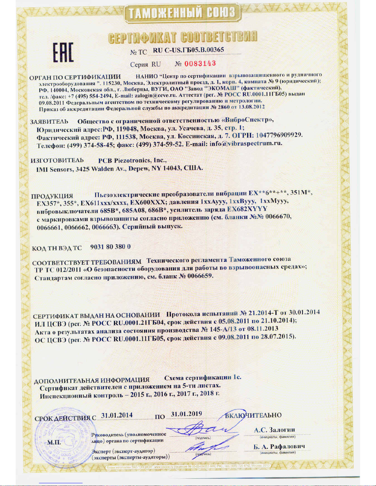
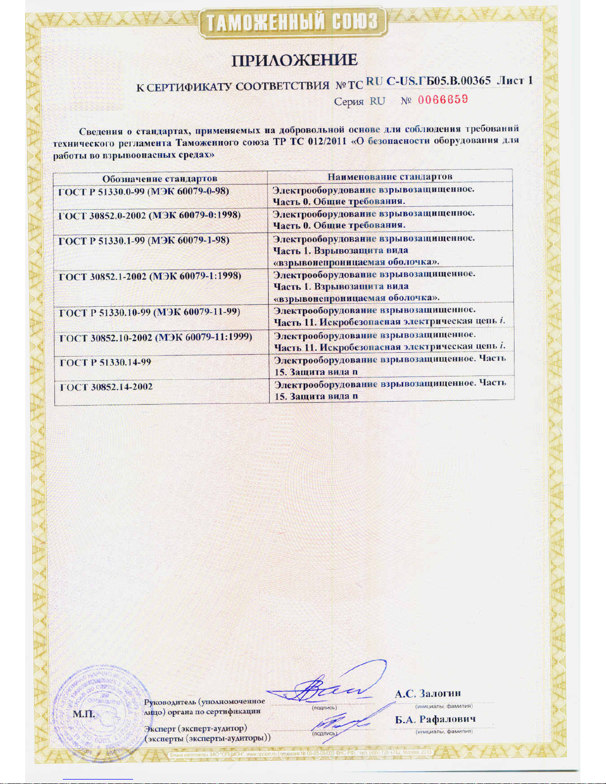
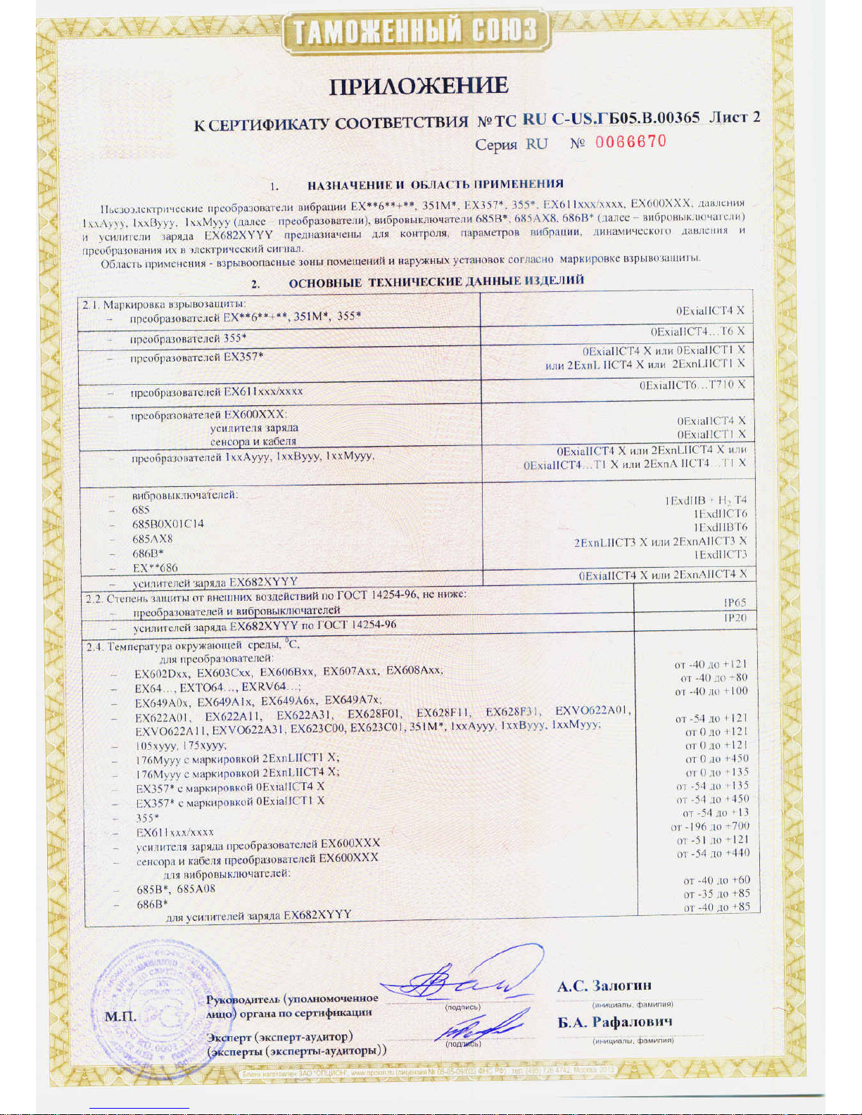
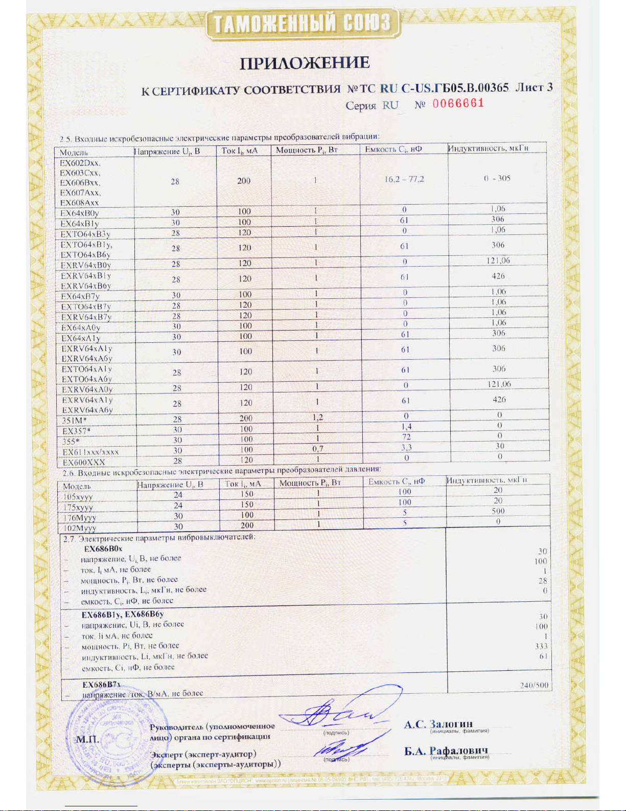
Model EX682M71
DIFFERENTIAL DIN RAIL CHARGE AMPLIFIER
Installation and Operating Manual
For assistance with the operation of this product,
contact PCB Piezotronics, Inc.
Toll-free: 800-828-8840
24-hour SensorLine: 716-684-0001
Fax: 716-684-0987
E-mail: [email protected]
Web: www.pcb.com
Page 2
Service, Repair, and Return
Policies and Instructions
The information contained in this document supersedes all similar information that
may be found elsewhere in this manual.
Service – Due to the sophisticated
nature of the sensors and associated
instrumentation provided by PCB
Piezotronics, user servicing or repair is
not recommended and, if attempted,
may void the factory warranty. Routine
maintenance, such as the cleaning of
electrical connectors, housings, and
mounting surfaces with solutions and
techniques that will not harm the
physical material of construction, is
acceptable. Caution should be observed
to ensure that liquids are not permitted
to migrate into devices that are not
hermetically sealed. Such devices
should only be wiped with a dampened
cloth and never submerged or have
liquids poured upon them.
Repair – In the event that equipment
becomes damaged or ceases to
operate, arrangements should be made
to return the equipment to PCB
Piezotronics for repair. User servicing or
repair is not recommended and, if
attempted, may void the factory
warranty.
Calibration – Routine calibration of
sensors and associated instrumentation
is recommended as this helps build
confidence in measurement accuracy
and acquired data. Equipment
calibration cycles are typically
established by the users own quality
regimen. When in doubt about a
calibration cycle, a good “rule of thumb”
is to recalibrate on an annual basis. It is
also good practice to recalibrate after
exposure to any severe temperature
extreme, shock, load, or other
environmental influence, or prior to any
critical test.
PCB Piezotronics maintains an ISO9001 certified metrology laboratory and
offers calibration services, which are
accredited by A2LA to ISO/IEC 17025,
with full traceability to SI through
N.I.S.T. In addition to the normally
supplied calibration, special testing is
also available, such as: sensitivity at
elevated or cryogenic temperatures,
phase response, extended high or low
frequency response, extended range,
leak testing, hydrostatic pressure
testing, and others. For information on
standard recalibration services or
special testing, contact your local PCB
Piezotronics distributor, sales
representative, or factory customer
service representative.
Returning Equipment – Following
these procedures will ensure that your
returned materials are handled in the
most expedient manner. Before
returning any equipment to PCB
Piezotronics, contact your local
distributor, sales representative, or
factory customer service representative
to obtain a Return Warranty, Service,
Repair, and Return Policies and
Instructions Materials Authorization
(RMA) Number. This RMA number
should be clearly marked on the outside
of all package(s) and on the packing
Page 3

list(s) accompanying the shipment. A
detailed account of the nature of the
problem(s) being experienced with the
equipment should also be included
inside the package(s) containing any
returned materials.
A Purchase Order, included with the
returned materials, will expedite the
turn-around of serviced equipment. It is
recommended to include authorization
on the Purchase Order for PCB to
proceed with any repairs, as long as
they do not exceed 50% of the
replacement cost of the returned
item(s). PCB will provide a price
quotation or replacement
recommendation for any item whose
repair costs would exceed 50% of
replacement cost, or any item that is not
economically feasible to repair. For
routine calibration services, the
Purchase Order should include
authorization to proceed and return at
current pricing, which can be obtained
from a factory customer service
representative.
Contact Information – International
customers should direct all inquiries to
their local distributor or sales office. A
complete list of distributors and offices
can be found at www.pcb.com.
Customers within the United States may
contact their local sales representative
or a factory customer service
representative. A complete list of sales
representatives can be found at
www.pcb.com. Toll-free telephone
numbers for a factory customer service
representative, in the division
responsible for this product, can be
found on the title page at the front of this
manual. Our ship to address and
general contact numbers are:
PCB Piezotronics, Inc.
3425 Walden Ave.
Depew, NY14043 USA
Toll-free: (800) 828-8840
24-hour SensorLineSM: (716) 684-0001
Website: www.pcb.com
E-mail: [email protected]
Page 4
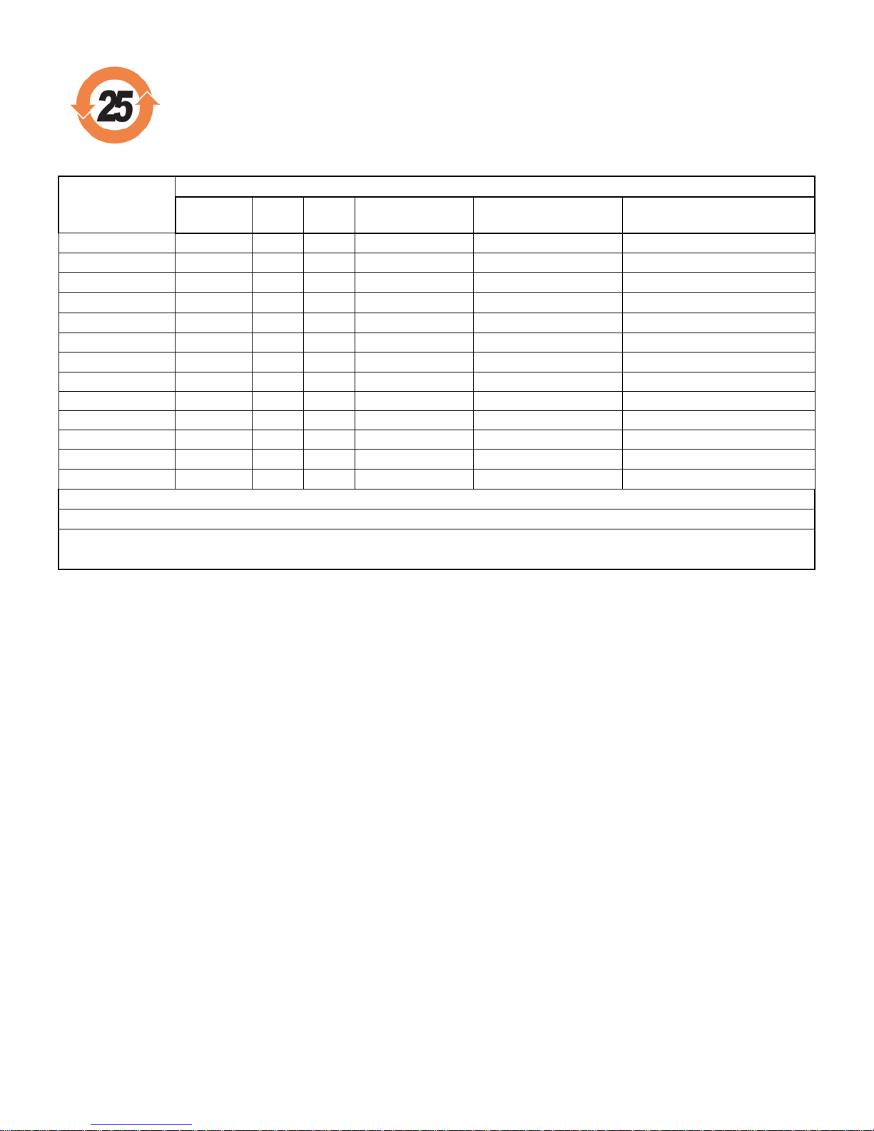
PCB工业监视和测量设备 - 中国RoHS2公布表
PCB Industrial Monitoring and Measuring Equipment - China RoHS 2 Disclosure Table
部件名称
有害物质
铅 (Pb)
汞
(Hg)
镉
(Cd)
六价铬 (Cr(VI))
多溴联苯 (PBB)
多溴二苯醚 (PBDE)
住房
O O O
O O O
PCB板
X O O
O O O
电气连接器
O O O
O O O
压电晶体
X O O
O O O
环氧
O O O
O O O
铁氟龙
O O O
O O O
电子
O O O
O O O
厚膜基板
O O X
O O O
电线
O O O
O O O
电缆
X O O
O O O
塑料
O O O
O O O
焊接
X O O
O O O
铜合金/黄铜
X O O
O O O
本表格依据 SJ/T 11364 的规定编制。
O: 表示该有害物质在该部件所有均质材料中的含量均在 GB/T 26572 规定的限量要求以下。
X: 表示该有害物质至少在该部件的某一均质材料中的含量超出 GB/T 26572 规定的限量要求。
铅是欧洲RoHS指令2011/65/ EU附件三和附件四目前由于允许的豁免。
CHINA RoHS COMPLIANCE
Page 5
Component Name
Hazardous Substances
Lead
(Pb)
Mercury
(Hg)
Cadmium
(Cd)
Chromium VI
Compounds
(Cr(VI))
Polybrominated
Biphenyls
(PBB)
Polybrominated
Diphenyl
Ethers (PBDE)
Housing O O O O O O
PCB Board
X O O O O
O
Electrical
Connectors
O O O O O
O
Piezoelectric
Crystals
X O O O O
O
Epoxy O O O O O O
Teflon O O O O O O
Electronics
O O O O O
O
Thick Film
Substrate
O O X O O
O
Wires O O O O O O
Cables X O O O O O
Plastic O O O O O O
Solder X O O O O O
Copper Alloy/Brass
X O O O O
O
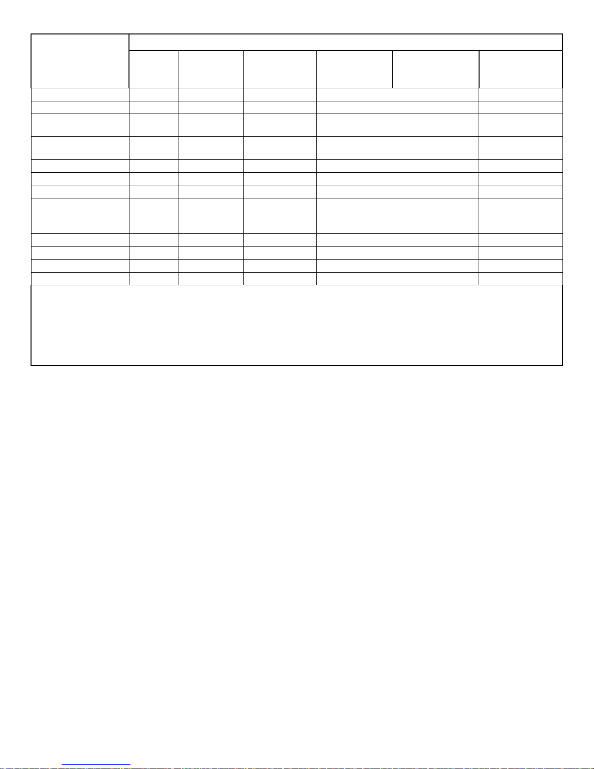
This table is prepared in accordance with the provisions of SJ/T 11364.
O: Indicates that said hazardous substance contained in all of the homogeneous materials for this part is below the limit
requirement of GB/T 26572.
X: Indicates that said hazardous substance contained in at least one of the homogeneous materials for this part is above
the limit requirement of GB/T 26572.
Lead is present due to allowed exemption in Annex III or Annex IV of the European RoHS Directive 2011/65/EU.
DOCUMENT NUMBER: 21354
DOCUMENT REVISION: D
ECN: 46162
Page 6
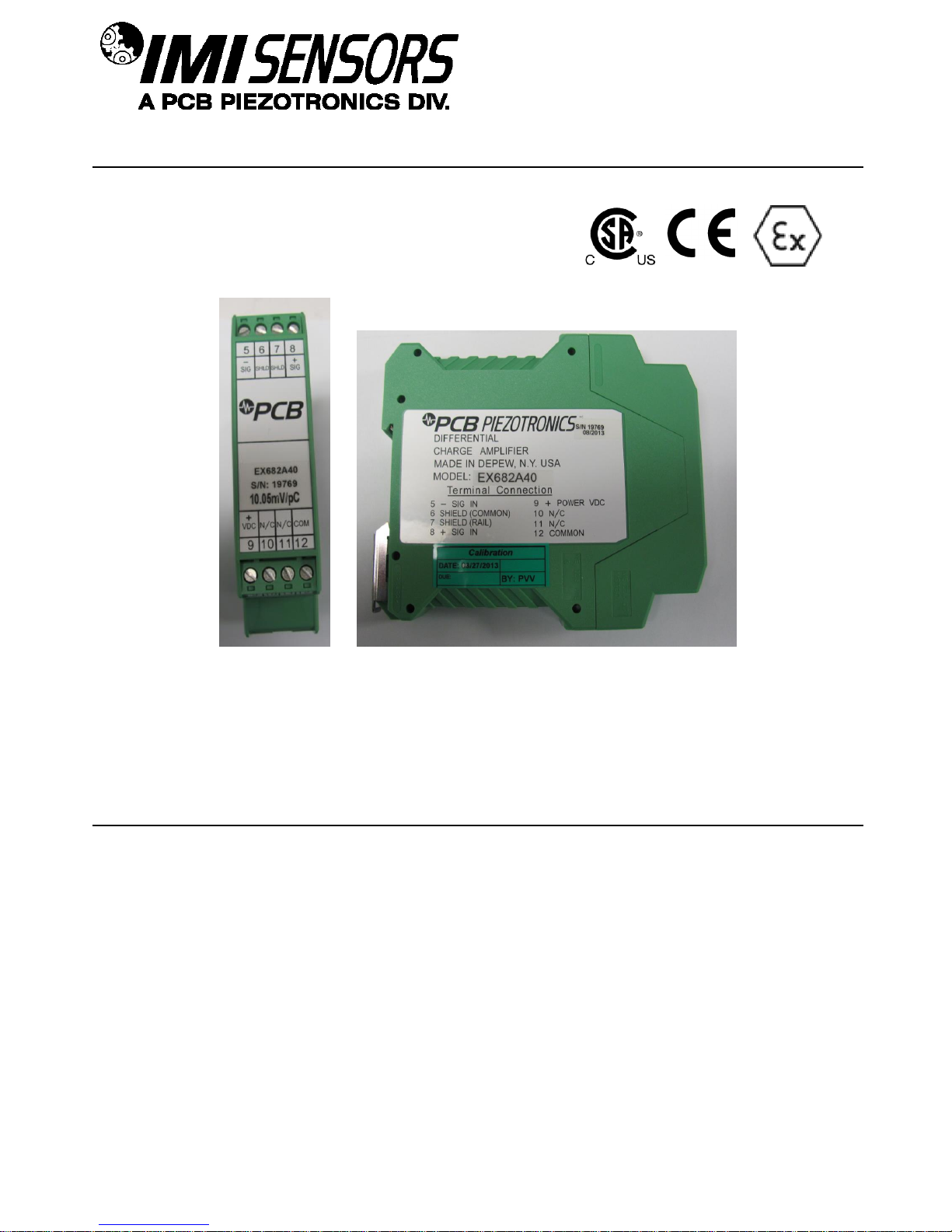
SENSORS AND INSTRUMENTATION FOR MACHINE CONDITION MONITORING
Model EX682 Series Differential Charge Amplifier
Operating Guide with Enclosed Warranty Information
3425 Walden Avenue, Depew, New York 14043-2495
Phone (716) 684-0003
Fax (716) 684-3823
Toll Free Line 1-800-959-4IMI
MANUAL NUMBER: 55855
MANUAL REVISION: D
ECN NUMBER: 47061
Page 7
SENSORS AND INSTRUMENTATION FOR MACHINE CONDITION MONITORING
Table of Contents
Introduction ...................................................................................................................... Page 3
General Features
Installation and Wiring .................................................................................................. Page 3-5
ESD Sensitivity ................................................................................................................ Page 6
Warranty/Servicing
Warranty, Service & Return Procedure ........................................................................... Page 7
Customer Service ............................................................................................................ Page 8
PAGE 2
Page 8
SENSORS AND INSTRUMENTATION FOR MACHINE CONDITION MONITORING
Introduction
The EX682 Series of differential charge input amplifiers are designed to interface with differential output charge
sensors. The unit will convert the charge signal from any differential output charge sensor into a voltage output.
The front end differential charge amplifiers are designed to handle low sensor resistance that is common at very
elevated temperatures (>500ºF). An ICP® Din Rail Signal Conditioner is required for use with the differential
charge amplifier, to provide the appropriate power supply.
General Features
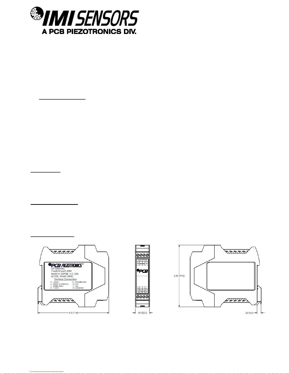
Din Rail Mount
Removable Terminal Blocks for easy wiring
35mm (1.38in.) Din Rail Mount configuration
Space saving 22.5mm (0.9in.) wide design
Installation and Wiring
Installation
The EX682 Series is designed to be mounted on a 35mm Din Rail. Do not install in a harsh area where it can be
exposed to cleaning fluids or machine oils. The unit should be mounted in a NEMA type enclosure to protect the
electronics from contamination.
CE Requirements
The EX682 Series is CE marked (see Declaration of Conformity for specific standards). To meet the requirement,
the unit must be installed in a grounded metallic enclosure and sensor cable shield terminated to enclosure.
Failure to do so can cause erroneous readings where high frequency noise is present.
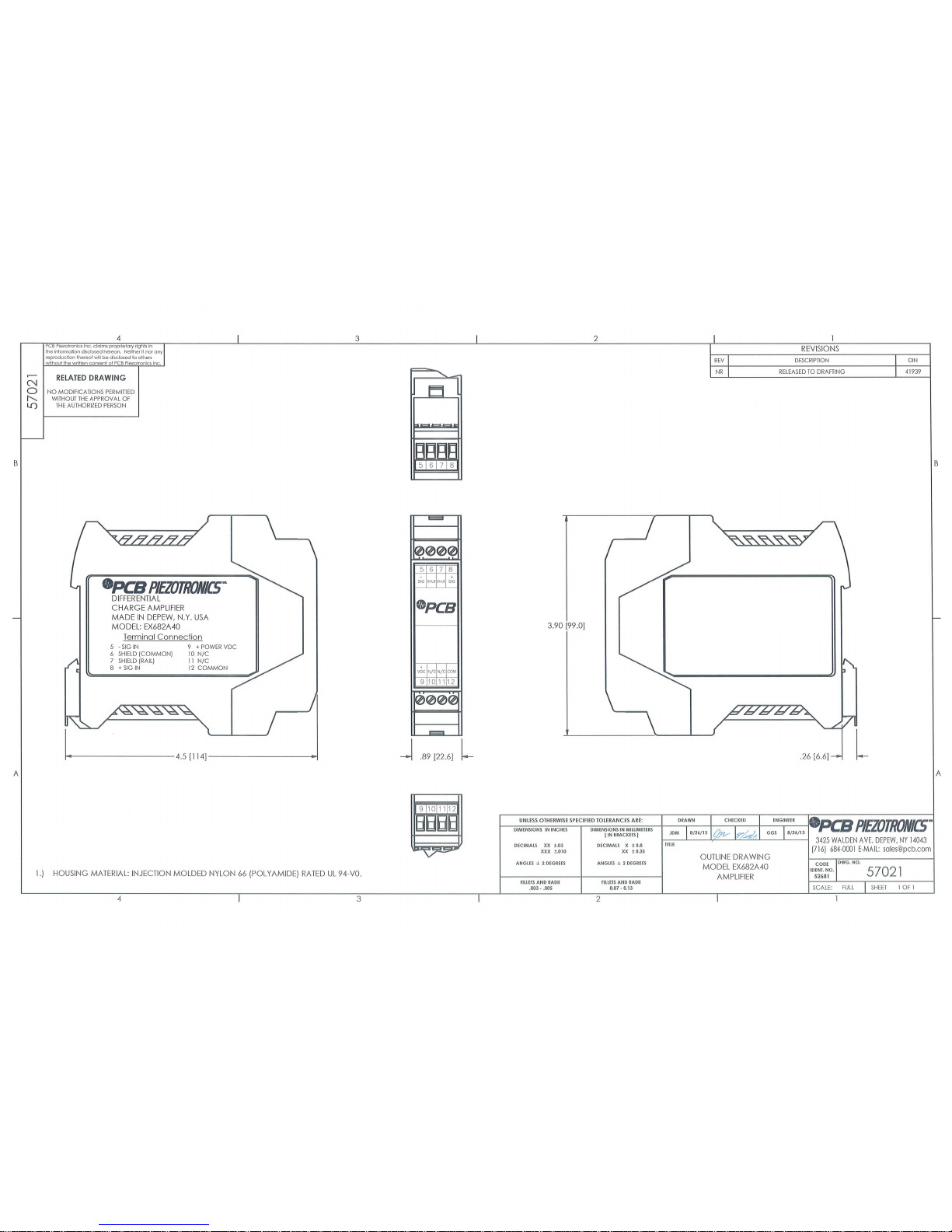
Outline Drawing
PAGE 3
Page 9
SENSORS AND INSTRUMENTATION FOR MACHINE CONDITION MONITORING
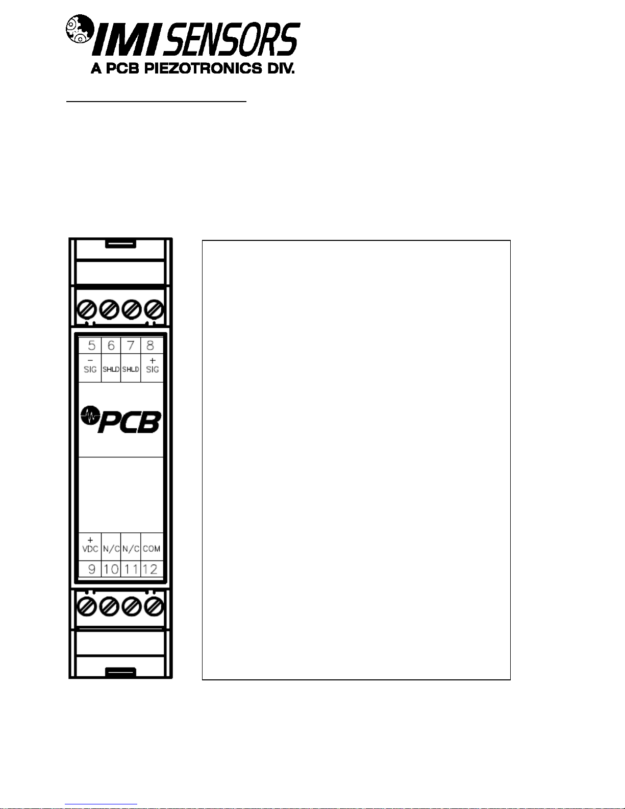
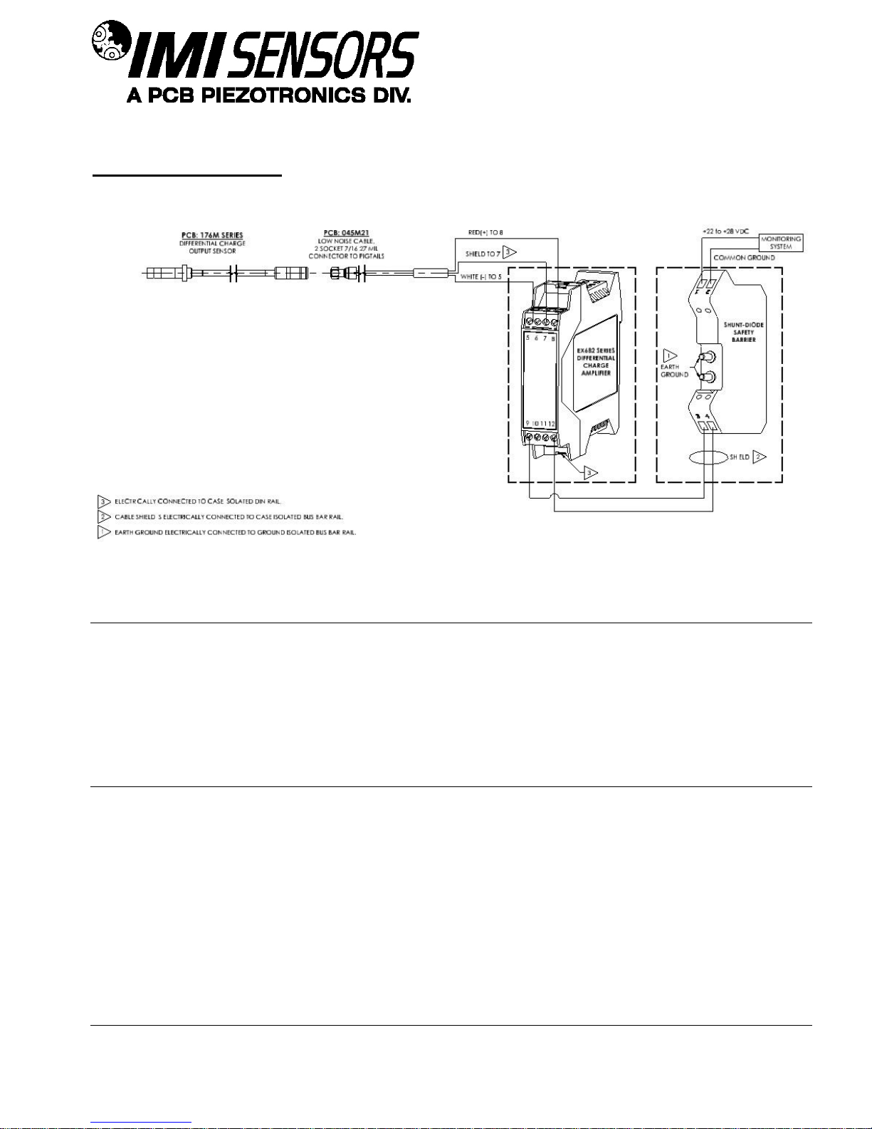
Pin Descriptions:
Pin 5: Sig –
Negative Charge Input Signal
Pin 6: Shield (Common)
This pin connects shield to Pin 12.
Pin 7: Shield (Rail)
This pin connects to the Din Rail bar that the
amplifier is mounted on.
Pin 8: Sig +
Positive Charge Input Signal
Pin 9: VDC +
Attach to the positive of ICP® power supply
Pin 10: N/C
No Connection
Pin 11: N/C
No Connection
Pin 12: Common
Attach to the negative of ICP® power supply
NOTE: An ICP® signal conditioner such as PCB Model
682A02 should be used to provide a constant
current ICP® power supply to Pins 9 and 12.
Connector and Pinout Diagram
The EX682 Series use plug-in type screw terminal connectors for all input and output connections.
Strip off ~8mm of insulation from the connection wire ends. Using a small screwdriver, remove the terminal block
from the enclosure in either the up or down direction, terminate the wire in the correct location. Do not exceed a
torque of 0.5Nm. Do not leave excess uninsulated wire which can short to adjacent wiring. Re-install the terminal
block.
This easy to assemble connection method allows devices to be exchanged easily and the electrical connection to
be visibly isolated.
PAGE 4
Page 10
SENSORS AND INSTRUMENTATION FOR MACHINE CONDITION MONITORING
Typical Wiring Diagram
Warning 1 – ESD sensitivity
personnel. This product is intended for use by qualified personnel who recognize shock hazards and are familiar
with the safety precautions required to avoid injury.
Warning 2 – ESD sensitivity
This equipment is designed with user safety in mind; however, the protection provided by the equipment may be
impaired if the equipment is used in a manner not specified by PCB Piezotronics, Inc.
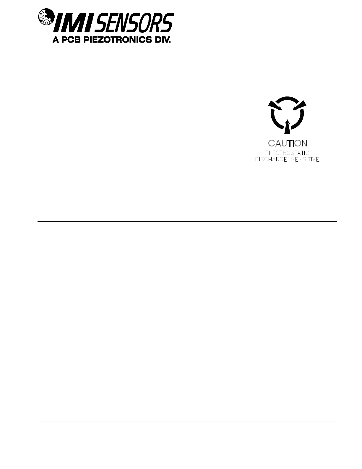
Caution 1 – ESD sensitivity
PAGE 5
Page 11
SENSORS AND INSTRUMENTATION FOR MACHINE CONDITION MONITORING
Cables can kill your equipment. High voltage electrostatic discharge (ESD) can damage electrical devices.
Similar to a capacitor, a cable can hold a charge caused by triboelectric transfer, such as that which occurs in the
following:
Laying on and moving across a rug,
Any movement through air,
The action of rolling out a cable, and/or
Contact with a non-grounded person.
The PCB solution for product safety:
Connect the cables only with the AC power off.
Temporarily “short” the end of the cable before attaching it to any signal input or output.
Caution 2 – ESD sensitivity
ESD considerations should be made prior to performing any internal adjustments on the equipment. Any
piece of electronic equipment is vulnerable to ESD when opened for adjustments. Internal adjustments should
therefore be done ONLY at an ESD-safe work area. Many products have ESD protection, but the level of
protection may be exceeded by extremely high voltage.
Warranty
IMI instrumentation is warranted against defective material and workmanship for 1 year unless otherwise
expressly specified. Damage to instruments caused by incorrect power or misapplication, is not covered by
warranty. If there are any questions regarding power, intended application, or general usage, please consult with
your local sales contact or distributor. Batteries and other expendable hardware items are not covered by
warranty.
PAGE 6
Page 12
SENSORS AND INSTRUMENTATION FOR MACHINE CONDITION MONITORING
Service
Because of the sophisticated nature of IMI instrumentation, field repair is typically NOT recommended and may
void any warranty. If factory service is required, return the instrumentation according to the “Return Procedure”
stated below. A repair and/or replacement quotation will be provided prior to servicing at no charge. Before
returning the unit, please consult a factory IMI applications engineer concerning the situation as certain problems
can often be corrected with simple on-site procedures.
Return procedure
To expedite returned instrumentation, contact a factory IMI applications engineer for a RETURN MATERIAL
AUTHORIZATION (RMA) NUMBER. Please have information available such as model and serial number. Also,
to insure efficient service, provide a written description of the symptoms and problems with the equipment to a
local sales representative or distributor, or contact IMI if none are located in your area.
Customers outside the U.S. should consult their local IMI distributor for information on returning equipment. For
exceptions, please contact the International Sales department at IMI to request shipping instructions and an RMA.
For assistance, please call (716) 684-0003, or fax us at (716) 684-3823. You may also receive assistance via email at [email protected] or visit our web site at www.pcb.com.
PAGE 7
Page 13
SENSORS AND INSTRUMENTATION FOR MACHINE CONDITION MONITORING
3425 Walden Avenue, Depew, NY 14043-2495
Phone: (716) 684-0003 USA Fax: (716) 684-3823 INTL Fax: (716) 684-4703
ICP® is a registered trademark of PCB Group, Incorporated,
which uniquely identifies PCB sensors that incorporate built-in microelectronics.
Customer Service
IMI, a division of PCB Piezotronics, guarantees Total Customer Satisfaction. If, at any time, for any reason, you
are not completely satisfied with any IMI product, IMI will repair, replace, or exchange it at no charge. You may
also choose, within the warranty period, to have your purchase price refunded.
IMI offers to all customers, at no charge, 24-hour phone support. This service makes product or application
support available to our customers, day or night, seven days a week. When unforeseen problems or emergency
situations arise, call the IMI Hot Line at (716) 684-0003, and an application specialist will assist you.
PAGE 8
Page 14
62912 REV. NR
ECO 44160
11/24/15
Page 15
62912 REV. NR
ECO 44160
11/24/15
Page 16
62912 REV. NR
ECO 44160
11/24/15
Page 17
62912 REV. NR
ECO 44160
11/24/15
Page 18
62912 REV. NR
ECO 44160
11/24/15
Page 19
62912 REV. NR
ECO 44160
11/24/15
Page 20
Model Number
EX682M71
DIFFERENTIAL DIN RAIL CHARGE AMPLIFIER
Revision: NR
ECN #: 42321
[3]
Performance
ENGLISH
SI
Sensitivity(+/-5 %)
5 mV/pC
5 mV/pC
Input Range
+/-250 pC
+/-250 pC
Low Frequency Response(+/-5 %)
5 Hz
5 Hz
High Frequency Response(+/-5 %)
10 kHz
10 kHz
[2]
Amplitude Linearity
≤ 1 %
≤ 1 %
Environmental
Hazardous Area Approval
IECEx LCIE 130002X
IECEx LCIE 130002X
Hazardous Area Approval
LCIE 13 ATEX 3031X
LCIE 13 ATEX 3031X
Hazardous Area Approval
Ex ia IIC T4 Ga
Ex ia IIC T4 Ga
Hazardous Area Approval
LCIE 13 ATEX 1010X
LCIE 13 ATEX 1010X
Hazardous Area Approval
Ex nA IIC T4 Gc
Ex nA IIC T4 Gc
Hazardous Area Approval
Class I Div 1 Groups A, B, C, D Class I Div 1 Groups A, B, C, D
Hazardous Area Approval
Class I Div 2 Groups A, B, C, D Class I Div 2 Groups A, B, C, D
Temperature Range(Operating)
-40 to +176 °F
-40 to 80 °C
Temperature Response
≤ 1 %
≤ 1 %
Relative Humidity(Non Condensing)
<95 %
<95 %
Electrical
Excitation Voltage
22 to 28 VDC
22 to 28 VDC
Constant Current Excitation
3.1 to 4.1 mA
3.1 to 4.1 mA
Output Voltage
+/-2.5 Vpk
+/-2.5 Vpk
Output Bias Voltage
10 to 12 VDC
10 to 12 VDC
Broadband Electrical Noise(1 to 10,000 Hz)
200 µV
200 µV
[1]
Spectral Noise(1 Hz)
50 µV/√Hz
50 µV/√Hz
[1]
Spectral Noise(10 Hz)
15 µV/√Hz
15 µV/√Hz
[1]
Spectral Noise(100 Hz)
5 µV/√Hz
5 µV/√Hz
[1]
Spectral Noise(1 kHz)
2 µV/√Hz
2 µV/√Hz
[1]
Spectral Noise(10 kHz)
2 µV/√Hz
2 µV/√Hz
[1]
Discharge Time Constant
>0.25 sec
>0.25 sec
Resistance
>50,000 Ohm
>50,000 Ohm
Source Capacitance Loading
0.0003 %/pF
0.0003 %/pF
Output in Relation to Input
In Phase
In Phase
Physical
Electrical Connector(Input)
Terminal Strip
Terminal Strip
Electrical Connector(Output)
Terminal Strip
Terminal Strip
Weight
5.1 oz
145 gm
Mounting
DIN Rail
DIN Rail
Case Material
Injected Molded Nylon
Injected Molded Nylon
All specifications are at room temperature unless otherwise specified.
In the interest of constant product improvement, we reserve the right to change
specifications without notice.
ICP® is a registered trademark of PCB Group, Inc.
OPTIONAL VERSIONS
Optional versions have identical specifications and accessories as listed for the standard model
except where noted below. More than one option may be used.
NOTES:
[1]
Typical value.
[2] Tested using voltage source and input capacitor equal to the feedback capacitor, to simulate
a charge output sensor.
[3]
See PCB Declaration of Conformance PS123 for details.
Entered: AP Engineer: gs Sales: EGY
Approved: BAM
Spec Number:
Date: 12/10/2013 Date: 12/10/2013 Date: 12/10/2013 Date: 12/10/2013
57782
3425 Walden Avenue, Depew, NY 14043
Phone: 716-684-0001
Fax: 716-684-0987
E-Mail: [email protected]
Page 21
Page 22
PCB PIEZOTRONICS INC.
3425 WALDEN AVE.
DEPEW, NEW YORK 14043
3425 Walden Ave
Depew, New York 14043
No 62271 N
o
1 of 2
Rev. A
ECO #: 45736
Model(s)
EX682XYYY series where “X” is a letter that signifies family type. The letter will be from A to M.
“YYY” is a number from 1 to 999 that signifies changes to filtering, gain frequency response etc..
Markings
PCB
Depew, NY
IECEx LCIE 13.0002X
LCIE 13 ATEX 3031 X
Ex ia IIC T4 Ga
LCIE 13 ATEX 1010 X
Ex nA IIC T4 Gc
Putting Into Service
Powering: All Charge Amplifiers require constant current excitation for proper operation. For this
reason, use only PCB constant-current signal conditioners or other approved constant-current sources.
The power supply consists of a current-regulated, 18 to 30 VDC source. This power is regulated by a
current-limiting circuit, which provides the constant-current excitation required for proper operation of
Charge Amplifiers.
In general, battery-powered devices offer versatility for portable, low-noise measurements, whereas
line-powered units provide the capability for continuous monitoring. Consult the Vibration Division’s
product catalog for more information about signal conditioners.
NOTE: Under no circumstances should a voltage be supplied to the Charge Amplifiers without a
current-regulating diode or equivalent electrical circuit. This may include ohmmeters, multi-meters
and continuity testers.
Safe Use
After completing the system setup, switch on the signal conditioner and allow 1 to 2 minutes for the
system to stabilize. The meter (or LED) on the signal conditioner should be reading “green.” This
indicates proper operation and you may begin taking measurements. If a faulty condition is indicated
(red or yellow reading), first check all system connections, then check the functionality of the cable and
signal conditioner. If the system still does not operate properly, consult a PCB factory representative.
NOTE: Always operate the Charge Amplifiers within the limitations listed on the enclosed
Specification Sheet. Operating the device outside these parameters can cause temporary or permanent
damage to the Charge Amplifiers.
Assembling
The EX682XYYY Series have green polyamide housing and do not require any assembly. Only
mounting on a 35mm Din Rail.
Dismantling
Other than removal from the mounting, there is no disassembly of the Charge Amplifiers required to
take it out of service.
Maintenance
Routine maintenance, such as the cleaning of electrical connectors, housings, and mounting surfaces
with solutions and techniques that will not harm the physical material of construction, is acceptable.
Servicing
Due to the sophisticated nature of the Charge Amplifiers and associated instrumentation provided by
PCB Piezotronics, user servicing or repair is not recommended and, if attempted, may void the factory
warranty. However, routine calibration of Charge Amplifiers and associated instrumentation is
recommended as this helps build confidence in measurement accuracy and acquired data.
Repair
In the event that equipment becomes damaged or ceases to operate, arrangements should be made to
return the equipment to PCB Piezotronics for repair. User servicing or repair is not recommended and,
if attempted, may void the factory warranty.
INSTRUCTIONS FOR USE –EX682XYYY Series
Page 23
PCB PIEZOTRONICS INC.
3425 WALDEN AVE.
DEPEW, NEW YORK 14043
3425 Walden Ave
Depew, New York 14043
No 62271 N
o
2 of 2
Rev. A
ECO #: 45736
Installation
Overview: The Charge Amplifiers are designed to be mounted on a 35mm Dain rail. Do note install in
a harsh area where it can be exposed to cleaning fluid or machine oils. The unit should be mounted in a
NEMA type enclosure to protect the electronics from contamination.
Cabling: Care and attention to cable installation and cable condition is essential as the reliability and
accuracy of any measurement system is no better than that of its weakest link. Due to the nature of
vibration measurements, all Charge Amplifiers cables will ultimately fatigue and fail. Good installation
practice will extend the life of a cable, however, it is highly recommended to keep spare cables on hand
to enable continuation of the test in the event of a cable failure.
Adjustment
No user adjustments are possible. However, routine calibration of Charge Amplifiers by the
manufacturer is recommended as this helps build confidence in measurement accuracy and acquired
data.
Danger Areas (for
pressure-relief devices)
N/A – not a pressure relief device.
Training Instructions
Industrial Charge Amplifiers must be installed in Hazardous Locations by trained professionals
according to EN/IEC 60079-14 requirements.
Details on Safety of
Protection Category
Ex ia is “intrinsic safety”, which limits the energy of sparks and surface temperatures to safe levels
Ex nA is “Non-Sparking”, which ensures that there is no risk of arcing and sparking or hot surfaces
during normal operation.
Entity Parameters and
Limits (Values)
Temperature Range: -40⁰C to +85C
Power Terminals (VDC, COM):
Ui ≤ 28V, Ii ≤ 100 mA, Pi ≤ 0.7W, Ci=0, Li = 0
Sensor Terminals (-SIG, +SIG, SHLD):
Uo ≤ 28V, Io ≤ 60 mA, Po ≤ 0.42W, Co=83nF, Li = 10mH
Special Conditions of
Use
Version Ex ia :
The equipment can be only connected to intrinsically safe certified equipment. These combinations
must be compatible as regard the intrinsic safety rules (see electrical parameters)
Version Ex nA:
The user must comply with the requirements of the instructions for use. The component shall be
installed in an enclosure conform to requirements of standard IEC 60079-0 and with ingress protection
at least IP54.
Essential Characteristics
of tools fitted to the
system (if any).
N/A – No tools are fitted to the system.
Drawings and Diagrams
54707,54708,54711,54712,54713,54714,65028,65092,54715,54716,54718
Other
Note: Literature (such as the manual or marketing materials) describing the equipment or protective system must
not contradict the instructions with regard to safety aspects.
Page 24
ATTESTATION D’EXAMEN DE TYPE
TYPE EXAMINATION CERTIFICATE
Seul le texte en français peut engager la responsabilité du LCIE. Ce document ne peut être reproduit que dans son intégralité , sans aucune modification. Il est
établi en accord avec le référentiel de certification ATEX du LCIE. The LCIE’s liability applies only on the French text. This
document may only be reproduced in
its entirety and without any change. It is issued in accordance with LCIE’s ATEX Certification Rules.
CERT-ATEX-FORM 05 Rev. 02 Page 1 of 3
1
Version
: 01
LCIE 13 ATEX 1010 X
Issue
: 01
Directive 2014/34/UE
Directive 2014/34/EU
2
Appareil ou Système de Protection destiné à être utilisé en
Atmosphères Explosibles
Equipment or Protective System Intended for use in Potentially
Explosive Atmospheres
3
Produit :
Product :
Amplificateur de charge
Charge amplifier
Type: EX682XYYY
4
Fabricant :
Manufacturer :
PCB Piezotronics Inc.
5
Adresse :
Address :
3425 Walden Avenue
Depew, New York 14043
USA
6
Ce produit et ses variantes éventuelles acceptées sont décrits
dans I'annexe de la présente attestation et dans les
documents descriptifs cités en référence.
This product any acceptable variation thereto is specified in the
schedule to this certificate and the documents therein referred
to.
7
Le LCIE certifie que ce produit est conforme aux Exigences
Essentielles de Sécurité et de Santé pour la conception et la
construction
de produits
destinés à être utilisés en
atmosphères explosibles, données dans l’annexe II de la
Directive.
LCIE certifies that product has been found to comply with the
Essential Health and Safety Requirements relating to the
design and construction of
products
intended for use in
potentially explosive atmospheres, given in Annex II to the
Directive.
Les résultats des vérifications et essais figurent dans le(s)
rapport(s) confidentiel(s) N° :
The examination and test results are recorded in confidential
report(s) N°:
117214-634396, 143150-689115.
8
Le respect des Exigences Essentielles de Sécurité et de Santé
est assuré par la conformité à :
Compliance with the Essential Health and Safety
Requirements has been assured by compliance with :
EN 60079-0:2012 +A11:2013, EN 60079-15:2010
9
Le signe « X » lorsqu'il est placé à la suite du numéro de
l’attestation, indique que cet appareil est soumis aux conditions
particulières d’utilisation, mentionnées dans l’annexe de cette
attestation.
If the sign “X” is placed after the certificate number, it indicates
that the
product is subject to
the Specific Conditions of Use
specified in the schedule to this certificate.
10
Cette Attestation d'Examen de Type concerne uniquement la
conception et la construction du produit spécifié.
This Type Examination Certificate relates only to the design
and construction of the specified product.
Des exigences supplémentaires de la directive sont applicables
pour la
fabrication et la fourniture du produit
. Ces dernières ne
sont pas couvertes par la présente attestation.
Further requirements of the Directive apply to the
manufacturing process and supply of
this product
. These are
not covered by this certificate.
11
Le marquage du produit est mentionné dans l’annexe de cette
attestation.
The marking of the product is specified in the schedule to this
certificate.
Fontenay-aux-Roses, le 30 septembre 2016
Responsable de Certification
Certification Officer
Julien Gauthier
Juenauthth
thierJuJuJulienenenen
Page 25
ATTESTATION D’EXAMEN DE TYPE - ANNEXE
TYPE EXAMINATION CERTIFICATE - SCHEDULE
Seul le texte en français peut engager la responsabilité du LCIE. Ce document ne peut être reproduit que dans son intégralité , sans aucune modification. Il est
établi en accord avec le référentiel de certification ATEX du LCIE. The LCIE’s liability applies only on the French text. This
document may only be reproduced in
its entirety and without any change. It is issued in accordance with LCIE’s ATEX Certification Rules.
CERT-ATEX-FORM 05 Rev. 02 Page 2 of 3
1
Version
: 01
LCIE 13 ATEX 1010 X
Issue
: 01
12
DESCRIPTION DU PRODUIT
DESCRIPTION OF PRODUCT
L’amplificateur de charge fournie une tension de sortie à partir
d’une charge d’entrée.
The charge amplifier provides a voltage output from a charge
input.
DETAIL DE LA GAMME
RANGE DETAILS
Définition du type :
EX682XYYY
X : désignation du type (A,
B,…M)
YYY : filtrage, gain, réponse en fréquence,… (1 à 999)
Type definition :
EX682XYYY
X : family type (A,
B,…M)
YYY : filtering, gain, frequency response,… (1 to 999)
Paramètres spécifiques du ou des modes de protection
concernés :
Specific parameters of the concerned protection mode :
U ≤ 28V, I ≤ 100mA, P ≤ 0.7W
MARQUAGE
MARKING
Le marquage du produit doit comprendre :
The marking of the product shall include the following :
PCB Piezotronics Inc.
Adresse : …
Type : EX682XYYY
(1)
Numéro de fabrication : …
Année de construction : …
II 3 G
Ex
nA IIC T4 Gc
LCIE 13 ATEX 1010 X
-40°C ≤ T
amb
≤ +85°C
(1)
complété en fonction du modèle
PCB Piezotronics Inc.
Address: ...
Type
: EX682XYYY
(1)
Serial number: ...
Year of construction: …
II 3 G
Ex nA IIC T4 Gc
LCIE 13 ATEX 1
010 X
-40°C ≤ T
amb
≤ +85°C
(1)
completed according to the model
L’appareil doit également comporter le marquage
normalement prévu par les normes de construction qui le
concernent sous la responsabilité du fabricant.
The equipment shall also bear the usual marking required by
the
product
standards applying to such equipment under the
manufacturer responsibility.
13
CONDITIONS PARTICULIERES D'UTILISATION
SPECIFIC CONDITIONS OF USE
Le composant doit être installé dans une enveloppe conforme
aux exigences de la norme EN 60079-0 et ayant un degré de
protection minimal IP54.
The component shall be installed in an enclosure conforming
to
the requirements of standard EN 60079-
0 and with ingress
protection at least IP54.
14
EXIGENCES ESSENTIELLES DE SANTE ET DE SECURITE
ESSENTIAL HEALTH AND SAFETY REQUIREMENTS
Couvertes par les normes listées au point 8.
Covered by standards listed at 8.
15
DOCUMENTS DESCRIPTIFS
DESCRIPTIVE DOCUMENTS
N°
Description
Reference
Rev.
Date
Page(s)
1.
Instructions
62771
A / 2
2.
Technical file
54707
A
2016/10/08
12
16
INFORMATIONS COMPLEMENTAIRES
ADDITIONAL INFORMATIONS
Essais individuels
Routine tests
Néant.
None.
En accord avec l’Article 41 de la Directive 2014/34/UE, les
attestations d’examen de type mentionnant la Directive
94/9/CE émises avant la date d’application de la Directive
2014/34/UE (20 avril 2016) peuvent être considérées comme
émises en accord avec la Directive 2014/34/UE. Les nouvelles
versions de ces attestations peuvent conserver le numéro de
l’attestation d’origine émise avant le 20 avril 2016.
In accordance with Article 41 of Directive 2014/34/EU, Type
Examination Certificates referring to
Directive
94/9/EC that
were in existence prior to the date of application of Directive
2014/34/EU (20 April 2016) may be referenced as if they were
issued in accordance with Directive 2014/34/EU. New issues
of such certificates may continue to bear the original certificate
number issued prior to 20 April 2016.
Page 26

ATTESTATION D’EXAMEN DE TYPE - ANNEXE
TYPE EXAMINATION CERTIFICATE - SCHEDULE
Seul le texte en français peut engager la responsabilité du LCIE. Ce document ne peut être reproduit que dans son intégralité , sans aucune modification. Il est
établi en accord avec le référentiel de certification ATEX du LCIE. The LCIE’s liability applies only on the French text. This
document may only be reproduced in
its entirety and without any change. It is issued in accordance with LCIE’s ATEX Certification Rules.
CERT-ATEX-FORM 05 Rev. 02 Page 3 of 3
1
Version
: 01
LCIE 13 ATEX 1010 X
Issue
: 01
17
DETAILS DES MODIFICATIONS
DETAILS OF CHANGES
Version00 :
14/06/2013
Evaluation initial
Issue 00 :
2013/06/14
Initial assessment
Version 01 :
Ajout d’un nouveau modèle (EX682M78).
Issue 01 :
Addition of a new model (EX682M78).
Page 27
ATTESTATION D’EXAMEN UE DE TYPE
EU TYPE EXAMINATION CERTIFICATE
Seul le texte en français peut engager la responsabilité du LCIE. Ce document ne peut être reproduit que dans son intégralité , sans aucune modification. Il est
établi en accord avec le référentiel de certification ATEX du LCIE. The LCIE’s liability applies only on the French text. This
document may only be reproduced in
its entirety and without any change. It is issued in accordance with LCIE’s ATEX Certification Rules.
CERT-ATEX-FORM 04 Rev. 02 Page 1 of 3
1
Version
: 01
LCIE 13 ATEX 3031 X
Issue
: 01
Directive 2014/34/UE
Directive 2014/34/EU
2
Appareil ou Système de Protection destiné à être utilisé en
Atmosphères Explosibles
Equipment or Protective System Intended for use in Potentially
Explosive Atmospheres
3
Produit :
Product :
Amplificateur de charge
Charge amplifier
Type: EX682XYYY
4
Fabricant :
Manufacturer :
PCB Piezotronics Inc.
5
Adresse :
Address :
3425 Walden Avenue
Depew, New York 14043
USA
6
Ce produit et ses variantes éventuelles acceptées sont décrits
dans I'annexe de la présente attestation et dans les
documents descriptifs cités en référence.
This product any acceptable variation thereto is specified in the
schedule to this certificate and the documents therein referred
to.
7
Le LCIE, Organisme Notifié sous la référence 0081
conformément à l’article 17 de la directive 2014/34/UE du
Parlement européen et du Conseil du 26 février 2014, certifie
que
ce produit
est conforme aux Exigences Essentielles de
Sécurité et de Santé pour la conception et la construction de
produits destinés à être utilisés en atmosphères explosibles,
données dans l’annexe II de la Directive.
LCIE, Notified Body number 0081 in accordance with article 17
of the Directive 2014/34/EU of the European Parliament and
the Council of 26 February 2014 certifies that
product has
been
found to comply with the Essential Health and Safety
Requirements relating to the design and construction of
products intended for use in potentially explosive atmospheres,
given in Annex II to the Directive.
Les résultats des vérifications et essais figurent dans le(s)
rapport(s) confidentiel(s) N° :
The examination and test results are recorded in confidential
report(s) N°:
117214-634396, 143150-689115
8
Le respect des Exigences Essentielles de Sécurité et de Santé
est assuré par la conformité à :
Compliance with the Essential Health and Safety
Requirements has been assured by compliance with :
EN 60079-0:2012 + A11:2013, EN 60079-11:2012
9
Le signe « X » lorsqu'il est placé à la suite du numéro de
l’attestation, indique que cet appareil est soumis aux conditions
particulières d’utilisation, mentionnées dans l’annexe de cette
attestation.
If the sign “X” is placed after the certificate number, it indicates
that the
product is subject to
the Specific Conditions of Use
specified in the schedule to this certificate.
10
Cette Attestation d'Examen UE de Type concerne uniquement
la conception et la construction du produit spécifié.
This EU Type Examination Certificate relates only to the design
and construction of the specified product.
Des exigences supplémentaires de la directive sont applicables
pour la fabrication et la fourniture
du produit
. Ces dernières ne
sont pas couvertes par la présente attestation.
Further requirements of the Directive apply to the
manufacturing process and s
upply of this product
. These are
not covered by this certificate.
11
Le marquage du produit est mentionné dans l’annexe de cette
attestation.
The marking of the product is specified in the schedule to this
certificate.
Fontenay-aux-Roses, le 30 septembre 2016
Responsable de Certification
Certification Officer
Julien Gauthier
JuenauauauthththierJulienen
Page 28
ATTESTATION D’EXAMEN UE DE TYPE - ANNEXE
EU TYPE EXAMINATION CERTIFICATE - SCHEDULE
Seul le texte en français peut engager la responsabilité du LCIE. Ce document ne peut être reproduit que dans son intégralité , sans aucune modification. Il est
établi en accord avec le référentiel de certification ATEX du LCIE. The LCIE’s liability applies only on the French text. This
document may only be reproduced in
its entirety and without any change. It is issued in accordance with LCIE’s ATEX Certification Rules.
CERT-ATEX-FORM 04 Rev. 02 Page 2 of 3
1
Version
: 01
LCIE 13 ATEX 3031 X
Issue
: 01
12
DESCRIPTION DU PRODUIT
DESCRIPTION OF PRODUCT
L’amplificateur de charge fournie une tension de sortie à partir
d’une charge d’entrée.
The charge amplifier provides a voltage output from a charge
input.
DETAIL DE LA GAMME
RANGE DETAILS
Définition du type : EX682XYYY
X
: désignation du type (A,B,…M)
YYY
: filtrage, gain, réponse en fréquence,… (1 à 999)
Type definition : EX682XYYY
X : family type (A,B,…M)
YYY : filtering, gain, frequency response,… (1 to 999)
Paramètres spécifiques du ou des modes de protection
concernés :
Specific parameters of the concerned protection mode:
Bornes d’alimentation (VDC, COM) :
U
i
: 28V, Ii : 100mA, Pi : 0.7W, Ci = 0, Li = 0
Bornes capteur (
-SIG, +SIG, SHLD) :
Uo : 28V, Io : 60mA, Po : 0.42W, Co : 83nF, Lo : 10mH
Power terminals (VDC, COM) :
Ui : 28V, Ii : 100mA, Pi : 0.7W, Ci = 0, Li = 0
Sensor terminals (
-SIG, +SIG, SHLD) :
Uo : 28V, Io : 60mA, Po : 0.42W, Co : 83nF, Lo : 10mH
MARQUAGE
MARKING
Le marquage du produit doit comprendre :
The marking of the product shall include the following :
PCB Piezotronics Inc.
Adresse
: …
Type : EX682
XYYY
(1)
N° de fabrication
: ...
Année de fabrication
: ...
II 1 G
Ex ia IIC T4 Ga
LCIE 13 ATEX 3031 X
-40°C ≤ T
amb
≤ +85°C
Bornes d’alimentation (VDC, COM)
:
U
i
: 28V, Ii : 100mA, Pi : 0.7W, Ci = 0, Li = 0
Bornes capteur (
-SIG, +SIG, SHLD) :
U
o
: 28V, Io : 60mA, Po : 0.42W, Co : 83nF, Lo : 10mH
(1)
complété en fonction du modèle
PCB Piezotronics Inc.
Address:
…
Type : EX682XYYY
(1)
Serial
number: …
Year of
construction: …
II 1 G
Ex ia IIC T4 Ga
LCIE 13 ATEX 3031 X
-40°C ≤ T
amb
≤ +85°C
Power terminals (VDC, COM)
:
U
i
: 28V, Ii : 100mA, Pi : 0.7W, Ci = 0, Li = 0
Sensor terminals (
-SIG, +SIG, SHLD) :
U
o
: 28V, Io : 60mA, Po : 0.42W, Co : 83nF, Lo : 10mH
(1)
completed according to the model
L’appareil doit également comporter le marquage
normalement prévu par les normes de construction qui le
concernent sous la responsabilité du fabricant.
The equipment shall also bear the usual marking required by
the
product
standards applying to such equipment under the
manufacturer responsibility.
13
CONDITIONS PARTICULIERES D'UTILISATION
SPECIFIC CONDITIONS OF USE
L’appareil ne peut être raccordé qu’à des appareils certifiés de
sécurité intrinsèque
ou à un appareil simple
. Ces associations
doivent être compatibles vis
-à-
vis de la sécurité intrinsèque
(voir les paramètres électriques au paragraphe 12).
The equipment can be only connected to intrinsically safe
certified equipment
or simple apparatus
. These combinations
must be compatible as regard the intrinsic safety rules (see
electrical parameters clause 12).
14
EXIGENCES ESSENTIELLES DE SANTE ET DE SECURITE
ESSENTIAL HEALTH AND SAFETY REQUIREMENTS
Couvertes par les normes listées au point 8.
Covered by standards listed at 8.
15
DOCUMENTS DESCRIPTIFS
DESCRIPTIVE DOCUMENTS
N°
Description
Reference
Rev.
Date
Page(s)
1.
Instructions
62771
A / 2
2.
Technical file
54707
A
2016/10/08
12
16
INFORMATIONS COMPLEMENTAIRES
ADDITIONAL INFORMATIONS
Essais individuels
Routine tests
Néant.
None.
Page 29

ATTESTATION D’EXAMEN UE DE TYPE - ANNEXE
EU TYPE EXAMINATION CERTIFICATE - SCHEDULE
Seul le texte en français peut engager la responsabilité du LCIE. Ce document ne peut être reproduit que dans son intégralité , sans aucune modification. Il est
établi en accord avec le référentiel de certification ATEX du LCIE. The LCIE’s liability applies only on the French text. This
document may only be reproduced in
its entirety and without any change. It is issued in accordance with LCIE’s ATEX Certification Rules.
CERT-ATEX-FORM 04 Rev. 02 Page 3 of 3
1
Version
: 01
LCIE 13 ATEX 3031 X
Issue
: 01
16
INFORMATIONS COMPLEMENTAIRES (suite)
ADDITIONAL INFORMATIONS (continued)
Conditions de certification
Conditions of certification
Les détenteurs d’attestations d’examen UE de type doivent
également satisfaire les exigences de contrôle de production
telles que définies à l’article 13 de la Directive 2014/34/UE.
Holders of EU type examination certificates are also required
to comply with the production control requirements defined in
article 13 of Directive 2014/34/EU.
En accord avec l’Article 41 de la Directive 2014/34/UE, les
attestations d’examen CE de type mentionnant la Directive
94/9/CE émises avant la date d’application de la Directive
2014/34/UE (20 avril 2016) peuvent être considérées comme
émises en accord avec la Directive 2014/34/UE. Les nouvelles
versions de ces attestations peuvent conserver le numéro de
l’attestation d’origine émise avant le 20 avril 2016.
In accordance with Article 41 of Directive 2014/34/EU, ECType Examination Certificates referring to
Directive
94/9/EC
that were in existence prior to the date of application of
Directive 2014/34/EU (20 April 2016) may be referenced as if
they were issued in accordance with Directive 2014/34/EU.
N
ew issues of such certificates
may continue to bear the
original certificate number issued prior to 20 April 2016.
17
DETAILS DES MODIFICATIONS
DETAILS OF CHANGES
Version 00 :
14/06/2013
Evaluation initial
Issue 00 :
2013/06/14
Initial assessment
Version 01 :
Ajout d’un nouveau modèle (EX682M78).
Issue 01 :
Addition of a new model (EX682M78).
Page 30
2016-09-30
Page 31
Page 32
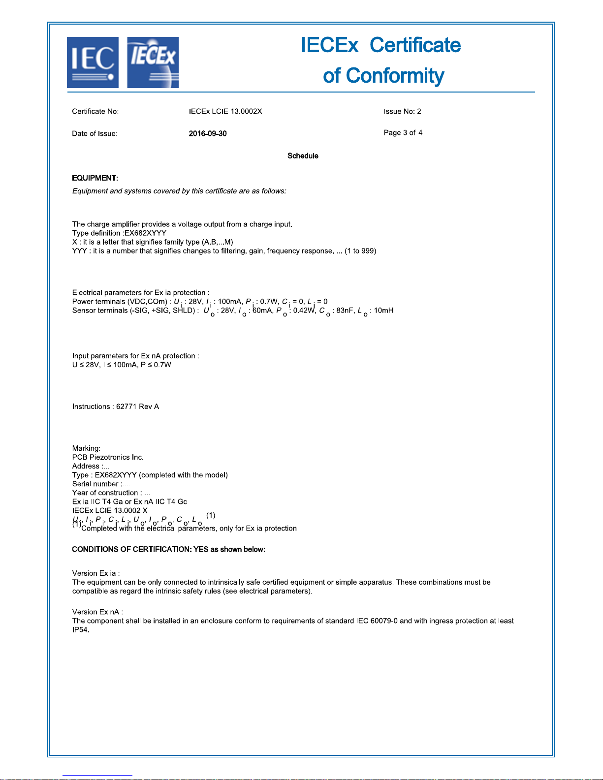
Page 33
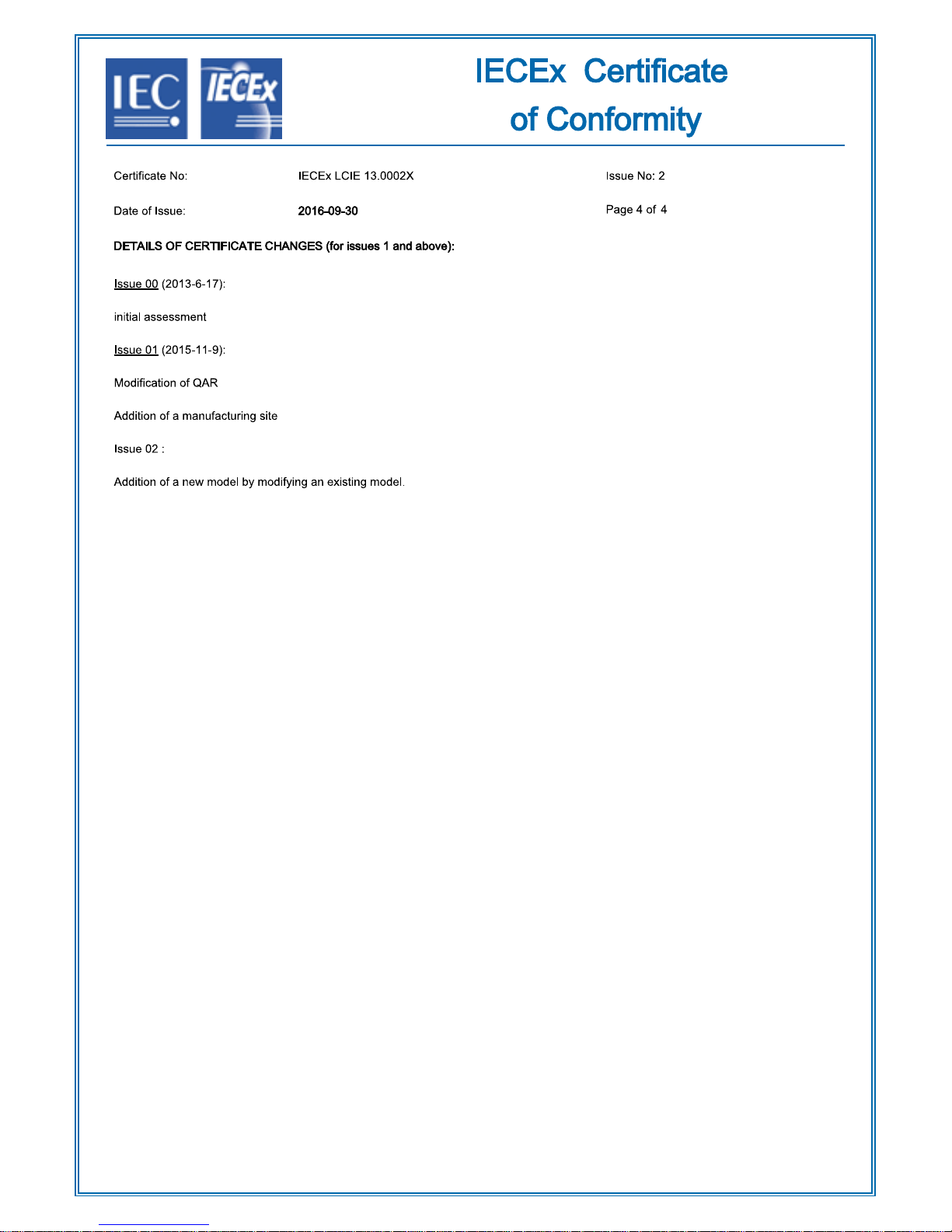
Page 34

Certificate of Compliance
Issued by:
Konstantin Rybalko
Konstantin Rybalko
ITEM # 57701
REV. A
ECO 46172
Certificate: 2646142 Master Contract: 184981 (103164_0_000)
Project: 70086425 Date Issued: 2016-10-27
Issued to: Industrial Monitoring Instr. (IMI) A Div. of PCB Piezotronics, Inc.
3425 Walden Ave
Depew, New York 14043
USA
Attention: Carrie Termin
The products listed below are eligible to bear the CSA Mark shown
PRODUCTS
CLASS - C225803 - PROCESS CONTROL EQUIPMENT - Intrinsically Safe and Non-Incendive Systems -
CLASS - C225883 - PROCESS CONTROL EQUIPMENT-Intrinsically Safe and Non-Incendive-Systems-
Class I, Division 1, Groups A, B, C and D:
- Model EX682XYYYY Differential Charge Amplifier, input rated 28 Vdc max, 20 mA max; intrinsically safe
with entity parameters at Power terminals (VDC, COM): Vmax (Ui) ≤ 28V, Imax (Ii) ≤ 100mA, Pi ≤ 0.7 W, Li =
10.8 µH, Ci = 0 ƞF; Sensor terminals (-SIG, +SIG): Voc (Uo) ≤ 28V, Isc (Io) ≤ 60 mA, Po ≤ 0.42W, Lo = 8 mH,
Co = 83 ƞF. Intrinsically safe when installed per installation Dwg. 56543; Temperature Code T4 at maximum
ambient 85⁰C.
Notes:
1. The Model EX682XYYYY shall be installed in a suitable enclosure acceptable to CSA or the local authority
having jurisdiction.
2. The Model EX682XYYYY can only be connected to intrinsically safe Certified equipment per installation
drawing.
For Hazardous Locations
For Hazardous Locations-Certified to U.S. Standards
Page 35

The Model codes suffixes are as follows:
CAN/CSA-C22.2 No. 0-2010
-
General Requirements – Canadian Electrical Code, Part II
C22.2 No. 142-M1987 (R2009)
-
Process Control Equipment
CAN/CSA-C22.2 No.157-92 (R2012)
-
Intrinsically Safe and Non-Incendive Equipment for Use in
Hazardous Locations
C22.2 No. 213-M1987 (R2008)
-
Non-Incendive Electrical Equipment for Use in Class I, Division 2
Hazardous Locations
UL 913-5Th Edition
-
Intrinsically Safe Apparatus and Associated Apparatus for Use in
Class I, II and III, Division 1, Hazardous Locations
UL 916-4Th Edition
-
Energy Management Equipment
ANSI/ISA 12.12.01-2012
-
Nonincendive Electrical Equipment for Use in Class I and II,
Division 2 and Class III, Divisions 1 and 2 Hazardous (Classified)
Locations
ITEM # 57701
REV. A
ECO 46172
X = family type: A – M
YYYY = different filtering, gain, frequency response: 0-9999.
Class I, Division 2, Groups A, B, C and D:
- Model EX682XYYYY Differential Charge Amplifier, input rated 28 Vdc max, 20mA max; non-incendive with
entity parameters at Power terminals (VDC, COM): Vmax (Ui) ≤ 28V, Imax (Ii) ≤ 100mA, Pi ≤ 0.7 W, Li = 10.8
µH, Ci = 0 ƞF; Sensor terminals (-SIG, +SIG): Voc (Uo) ≤ 28V, Isc (Io) ≤ 60 mA, Po ≤ 0.42W, Lo ≤ 8 mH, Co ≤
83 ƞF. Refer to installation Dwg. 56543; Temperature Code T4 at maximum ambient 85⁰C.
Notes:
1. The Model EX682XYYYY shall be installed in a suitable enclosure acceptable to CSA or the local authority
having jurisdiction.
2. The Model EX682XYYYY shall only be connected to non-incendive Certified equipment per installation
drawing.
The Model codes suffixes are as follows:
X = family type: A – M
YYYY = different filtering, gain, frequency response: 0-9999.
APPLICABLE REQUIREMENTS
Page 36

Supplement to Certificate of Compliance
Project
Date
Description
70086425
2016-10-27
Update to report 2646142 to include schematic change.
2646142
2013-11-08
Original Certification of EX682XYYYY
ITEM # 57701
REV. A
ECO 46172
Certificate: 2646142 Master Contract: 184981 (103164_0_000)
The products listed, including the latest revision described below,
are eligible to be marked in accordance with the referenced Certificate.
Product Certification History
Page 37
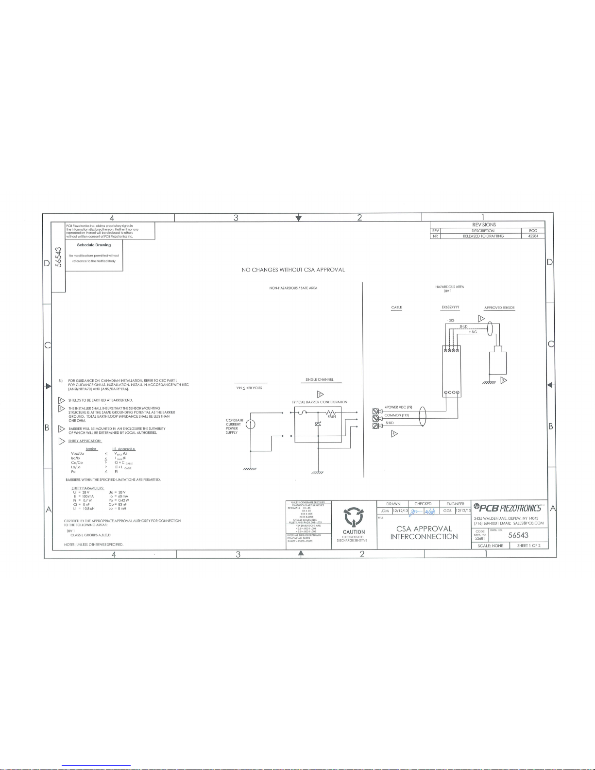
Page 38
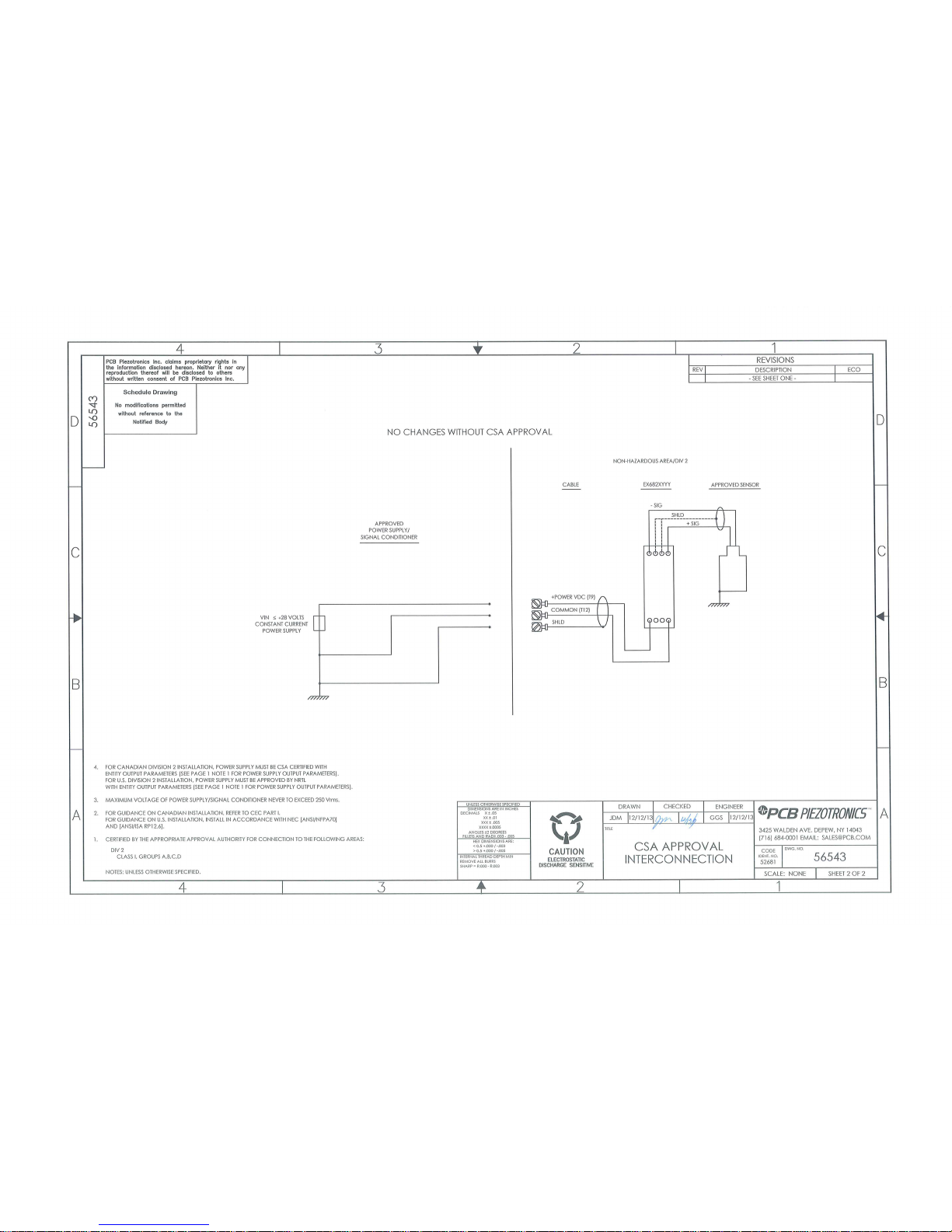
 Loading...