

Page 1

Model 485M49
Airborne Amplifier, 3-Channel ICP® , +28 VDC aircraft powered
Installation and Operating Manual
For assistance with the operation of this product,
contact PCB Piezotronics, Inc.
Toll-free: 800-828-8840
24-hour SensorLine: 716-684-0001
Fax: 716-684-0987
E-mail: [email protected]
Web: www.pcb.com
Page 2

Warranty, Service, Repair, and
Return Policies and Instructions
The informati on contained in this document supersedes all similar i nformation th at
may be found elsewhere in this manual.
Total Customer Satisfaction – PCB
Piezotronics guarantees Total Customer
Satisfaction. If, at any time, for any
reason, you are not completely satisfied
with any PCB product, PCB will repair,
replace, or exchange it at no charge. You
may also choose to have your purchase
price refunded in lieu of the repair,
replacement, or exchange of the product.
Service – Due to the sophisticated nature
of the sensors and associated
instrumentation provided by PCB
Piezotronics, user servicing or repair is
not recommended and, if attempted, may
void the factory warranty. Routine
maintenance, such as the cleaning of
electrical connectors, housings, and
mounting surfaces with solutions and
techniques that will not harm the
physical material of construction, is
acceptable. Caution should be observed
to insure that liquids are not permitted to
migrate into devices that are not
hermetically sealed. Such devices should
only be wiped with a dampened cloth
and never submerged or have liquids
poured upon them.
Repair – In the event that equipment
becomes damaged or ceases to operate,
arrangements should be made to return
the equipment to PCB Piezotronics for
repair. User servicing or repair is not
recommended and, if attempted, may
void the factory warranty.
Calibration – Routine calibration of
sensors and associated instrumentation is
recommended as this helps build
confidence in measurement accuracy and
acquired data. Equipment calibration
cycles are typically established by the
users own quality regimen. When in
doubt about a calibration cycle, a good
“rule of thumb” is to recalibrate on an
annual basis. It is also good practice to
recalibrate after exposure to any severe
temperature extreme, shock, load, or
other environmental influence, or prior
to any critical test.
PCB Piezotronics maintains an ISO9001 certified metrology laboratory and
offers calibration services, which are
accredited by A2LA to ISO/IEC 17025,
with full traceablility to N.I.S.T. In
addition to the normally supplied
calibration, special testing is also
available, such as: sensitivity at elevated
or cryogenic temperatures, phase
response, extended high or low
frequency response, extended range, leak
testing, hydrostatic pressure testing, and
others. For information on standard
recalibration services or special testing,
contact your local PCB Piezotronics
distributor, sales representative, or
factory customer service representative.
Returning Equipment – Following
these procedures will insure that your
returned materials are handled in the
most expedient manner. Before returning
any equipment to PCB Piezotronics,
contact your local distributor, sales
representative, or factory customer
service representative to obtain a Return
Page 3

Materials Authorization (RMA)
Number. This RMA number should be
clearly marked on the outside of all
package(s) and on the packing list(s)
accompanying the shipment. A detailed
account of the nature of the problem(s)
being experienced with the equipment
should also be included inside the
package(s) containing any returned
materials.
A Purchase Order, included with the
returned materials, will expedite the
turn-around of serviced equipment. It is
recommended to include authorization
on the Purchase Order for PCB to
proceed with any repairs, as long as they
do not exceed 50% of the replacement
cost of the returned item(s). PCB will
provide a price quotation or replacement
recommendation for any item whose
repair costs would exceed 50% of
replacement cost, or any item that i s not
economically feasible to repair. For
routine calibration services, the Purchase
Order should include authorization to
proceed and return at current pricing,
which can be obtained from a factory
customer service representative.
Warranty – All equipment and repair
services provided by PCB Piezotronics,
Inc. are covered by a limited warranty
against defective material and
workmanship for a period of one year
from date of original purchase. Contact
DOCUMENT NUMBER: 21354
DOCUMENT REVISION: B
ECN: 17900
PCB for a complete statement of our
warranty. Expendable items, such as
batteries and mounting hardware, are not
covered by warranty. Mechanical
damage to equipment due to improper
use is not covered by warranty.
Electronic circuitry failure caused by the
introduction of unregulated or improper
excitation power or electrostatic
discharge is not covered by warranty.
Contact Information – International
customers should direct all inquiries to
their local distributor or sales office. A
complete list of distributors and offices
can be found at www.pcb.com.
Customers within the United States may
contact their local sales representative or
a factory customer service
representative. A complete list of sales
representatives can be found at
www.pcb.com. Toll-free telephone
numbers for a factory customer service
representative, in the division
responsible for this product, can be
found on the title page at the front of this
manual. Our ship to address and general
contact numbers are:
PCB Piezotronics, I nc.
3425 Walden Ave.
Depew, NY 14043 USA
Toll-free: (800) 828-8840
24-hour SensorLine
SM
: (716) 684-0001
Website: www.pcb.com
E-mail: [email protected]
Page 4
Model Number
485M49
AIRBORNE AMPLIFIER, 3-CHANNEL ICP® , +28 VDC AIRCRAFT POWERED
Revision: B
ECN #: 43617
Performance ENGLISH SI
High Frequency Response(-5 %) >100 kHz >100 kHz [1]
Low Frequency Response(-5 %) <1.0 Hz <1.0 Hz [1]
Environmental
Temperature Range -40 to 185 °F -40 to 85 °C
Electrical
Supply Voltage 18 to 30 VDC 18 to 30 VDC
Output VDC(Offset) <10 ±mV <10 ±mV
Supply Current(for ICP Sensor)(Internal Current Lim iter) 4.0 (+/- 1.0) mA DC 4.0 (+/- 1.0) mA DC
Physical
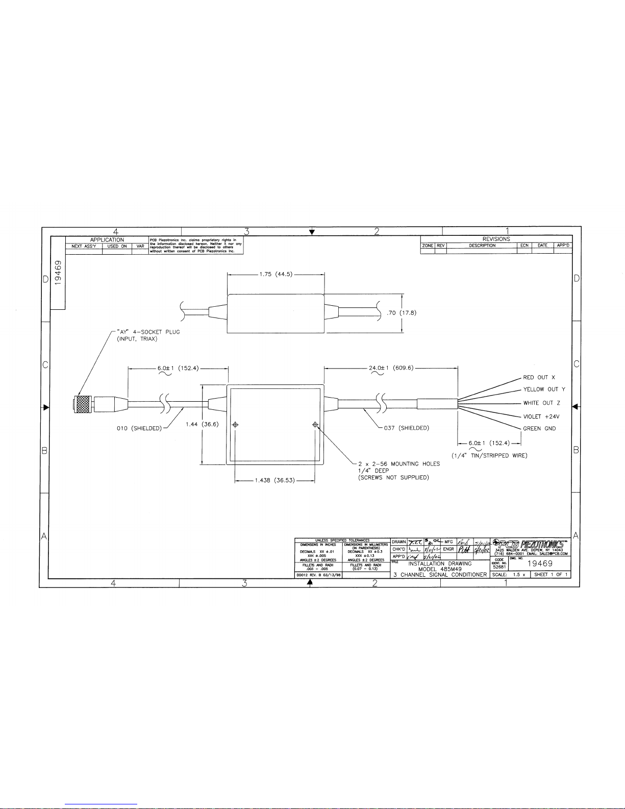
Cable Output(Integral) 037 type 24" Long (w/6" S&T BZ)
Cable Output(Supply Voltage) Violet Violet
Cable Output(GND) Green Green
Cable Output(X Axis) Red Red
Cable Output(Y Axis) Yellow Yellow
Cable Output(Z Axis) White White
Cable Sensor(Integral) 010 type Conn # AY PCB Triax 6" Lo ng
Size (Height x Length x Width) 1.45 in x 0.70 in x 2.90 in 3.68 cm x 1.78 cm x 7.37 cm
Weight 2.47 oz 70 gm
All specifications are at room temperature unless otherwis e specified.
In the interest of constant product improvement, we rese rve the right to change specifications without notice.
ICP® is a registered trademark of PCB Group, Inc.
NOTES:
[1]Un-buffered output, read out device input impedance affects discharge time constant and low
frequency response of unit.
3425 Walden Avenue, Depew, NY 14043
Phone: 716-684-0001
Fax: 716-684-0987
E-Mail: [email protected]
OPTIONAL VERSIONS
Optional versions have identical specifications and acc essories as listed for the standard
model except where noted below. More than one option m ay be used.
Entered: AP Engineer: CPH Sales: ML Approved: JWH Spec Number:
Date: 2/3/2015 Date: 2 /3/2015 Date: 2/3/2015 Date: 2/3/2015
17511
Page 5
 Loading...