

PCB Piezotronics 101A02, 101A06, 101A03, 111A22, 101A04 Installation And Operating Manual
...
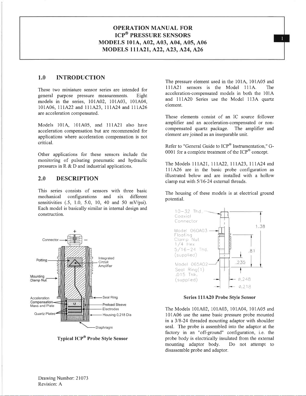
Model S111A26
General purpose ICP® pressure probe, 500 psi, 10 mV/psi, 0.218" dia.
Installation and Operating Manual
For assistance with the operation of this product,
contact PCB Piezotronics, Inc.
Toll-free: 800-828-8840
24-hour SensorLine: 716-684-0001
Fax: 716-684-0987
E-mail: info@pcb.com
Web: www.pcb.com
Warranty, Service, Repair, and
Return Policies and Instructions
The information contained in this document supersedes all similar information that
may be found elsewhere in this manual.
Total Customer Satisfaction – PCB
Piezotronics guarantees Total Customer
Satisfaction. If, at any time, for any
reason, you are not completely satisfied
with any PCB product, PCB will repair,
replace, or exchange it at no charge.
You may also choose to have your
purchase price refunded in lieu of the
repair, replacement, or exchange of the
product.
Service – Due to the sophisticated
nature of the sensors and associated
instrumentation provided by PCB
Piezotronics, user servicing or repair is
not recommended and, if attempted,
may void the factory warranty. Routine
maintenance, such as the cleaning of
electrical connectors, housings, and
mounting surfaces with solutions and
techniques that will not harm the
physical material of construction, is
acceptable. Caution should be observed
to insure that liquids are not permitted to
migrate into devices that are not
hermetically sealed. Such devices
should only be wiped with a dampened
cloth and never submerged or have
liquids poured upon them.
Repair – In the event that equipment
becomes damaged or ceases to
operate, arrangements should be made
to return the equipment to PCB
Piezotronics for repair. User servicing or
repair is not recommended and, if
attempted, may void the factory
warranty.
Calibration – Routine calibration of
sensors and associated instrumentation
is recommended as this helps build
confidence in measurement accuracy
and acquired data. Equipment
calibration cycles are typically
established by the users own quality
regimen. When in doubt about a
calibration cycle, a good “rule of thumb”
is to recalibrate on an annual basis. It is
also good practice to recalibrate after
exposure to any severe temperature
extreme, shock, load, or other
environmental influence, or prior to any
critical test.
PCB Piezotronics maintains an ISO9001 certified metrology laboratory and
offers calibration services, which are
accredited by A2LA to ISO/IEC 17025,
with full traceability to SI through
N.I.S.T. In addition to the normally
supplied calibration, special testing is
also available, such as: sensitivity at
elevated or cryogenic temperatures,
phase response, extended high or low
frequency response, extended range,
leak testing, hydrostatic pressure
testing, and others. For information on
standard recalibration services or
special testing, contact your local PCB
Piezotronics distributor, sales
representative, or factory customer
service representative.
Returning Equipment – Following
these procedures will insure that your
returned materials are handled in the
most expedient manner. Before

returning any equipment to PCB
Piezotronics, contact your local
distributor, sales representative, or
factory customer service representative
to obtain a Return Warranty, Service,
Repair, and Return Policies and
Instructions Materials Authorization
(RMA) Number. This RMA number
should be clearly marked on the outside
of all package(s) and on the packing
list(s) accompanying the shipment. A
detailed account of the nature of the
problem(s) being experienced with the
equipment should also be included
inside the package(s) containing any
returned materials.
A Purchase Order, included with the
returned materials, will expedite the
turn-around of serviced equipment. It is
recommended to include authorization
on the Purchase Order for PCB to
proceed with any repairs, as long as
they do not exceed 50% of the
replacement cost of the returned
item(s). PCB will provide a price
quotation or replacement
recommendation for any item whose
repair costs would exceed 50% of
replacement cost, or any item that is not
economically feasible to repair. For
routine calibration services, the
Purchase Order should include
authorization to proceed and return at
current pricing, which can be obtained
from a factory customer service
representative.
Warranty – All equipment and repair
services provided by PCB Piezotronics,
Inc. are covered by a limited warranty
against defective material and
workmanship for a period of one year
from date of original purchase. Contact
PCB for a complete statement of our
warranty. Expendable items, such as
batteries and mounting hardware, are
not covered by warranty. Mechanical
damage to equipment due to improper
use is not covered by warranty.
Electronic circuitry failure caused by the
introduction of unregulated or improper
excitation power or electrostatic
discharge is not covered by warranty.
Contact Information – International
customers should direct all inquiries to
their local distributor or sales office. A
complete list of distributors and offices
can be found at www.pcb.com.
Customers within the United States may
contact their local sales representative
or a factory customer service
representative. A complete list of sales
representatives can be found at
www.pcb.com. Toll-free telephone
numbers for a factory customer service
representative, in the division
responsible for this product, can be
found on the title page at the front of this
manual. Our ship to address and
general contact numbers are:
PCB Piezotronics, Inc.
3425 Walden Ave.
Depew, NY14043 USA
Toll-free: (800) 828-8840
24-hour SensorLineSM: (716) 684-0001
Website: www.pcb.com
E-mail: info@pcb.com
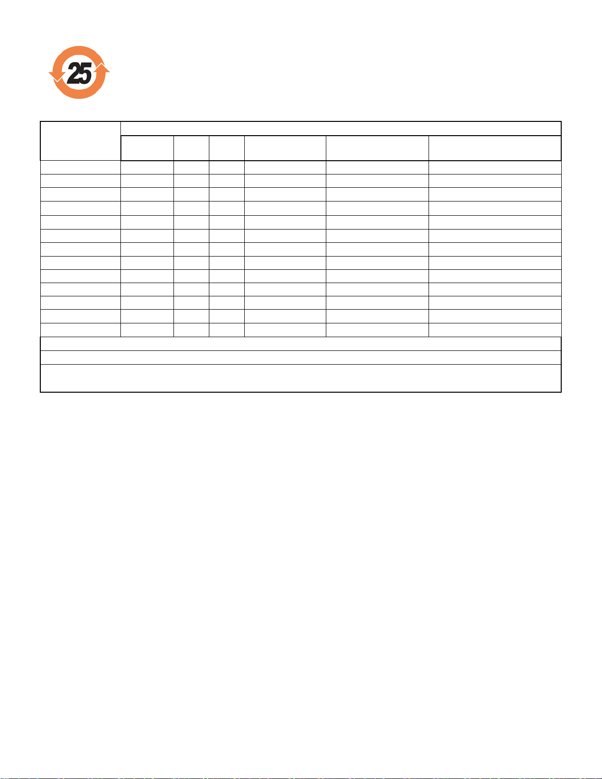
PCB工业监视和测量设备 - 中国RoHS2公布表
PCB Industrial Monitoring and Measuring Equipment - China RoHS 2 Disclosure Table
部件名称
有害物质
铅 (Pb)
汞
(Hg)
镉
(Cd)
六价铬 (Cr(VI))
多溴联苯 (PBB)
多溴二苯醚 (PBDE)
住房
O O O
O O O
PCB板
X O O
O O O
电气连接器
O O O
O O O
压电晶体
X O O
O O O
环氧
O O O
O O O
铁氟龙
O O O
O O O
电子
O O O
O O O
厚膜基板
O O X
O O O
电线
O O O
O O O
电缆
X O O
O O O
塑料
O O O
O O O
焊接
X O O
O O O
铜合金/黄铜
X O O
O O O
本表格依据 SJ/T 11364 的规定编制。
O: 表示该有害物质在该部件所有均质材料中的含量均在 GB/T 26572 规定的限量要求以下。
X: 表示该有害物质至少在该部件的某一均质材料中的含量超出 GB/T 26572 规定的限量要求。
铅是欧洲RoHS指令2011/65/ EU附件三和附件四目前由于允许的豁免。
CHINA RoHS COMPLIANCE
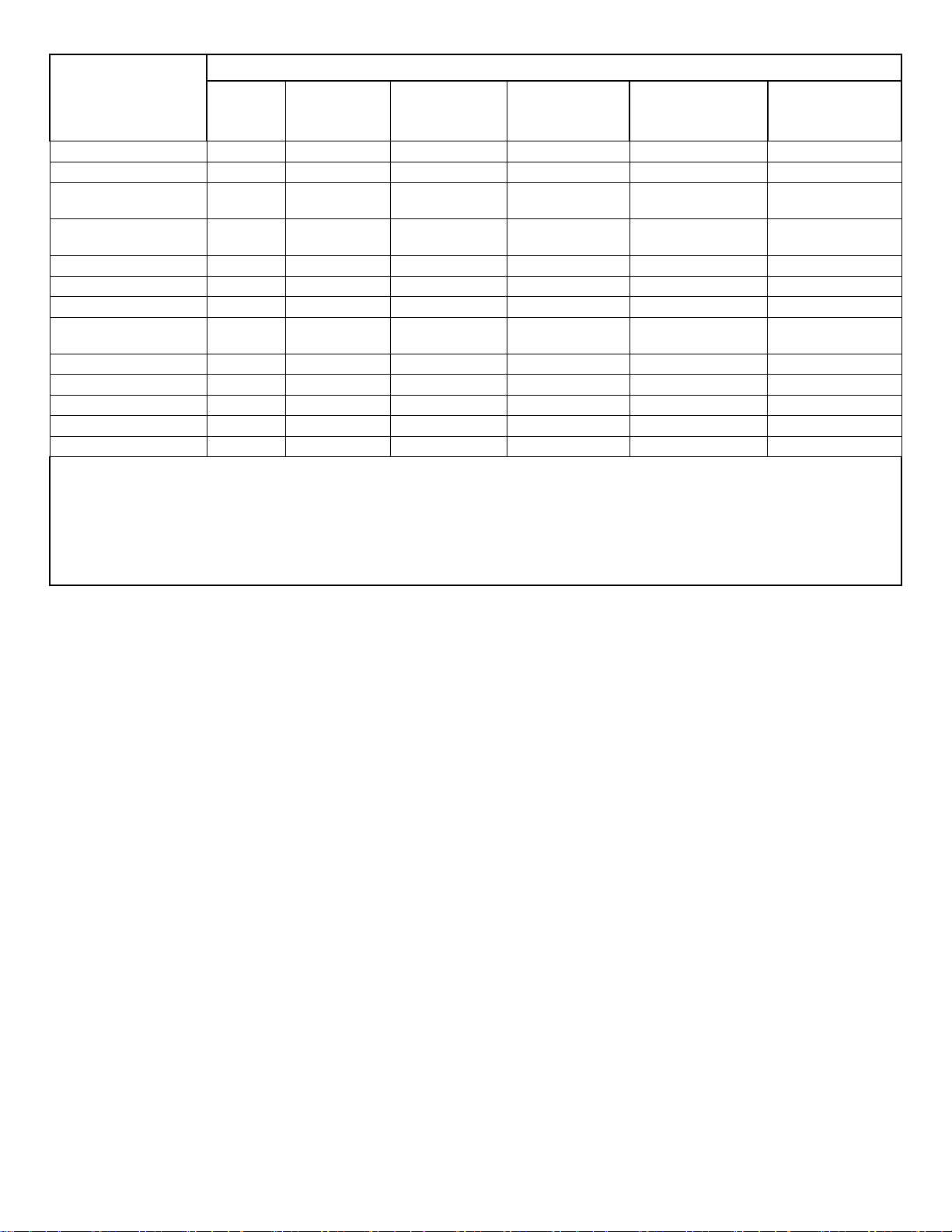
Component Name
Hazardous Substances
Lead
(Pb)
Mercury
(Hg)
Cadmium
(Cd)
Chromium VI
Compounds
(Cr(VI))
Polybrominated
Biphenyls
(PBB)
Polybrominated
Diphenyl
Ethers (PBDE)
Housing O O O O O O
PCB Board
X O O O O
O
Electrical
Connectors
O O O O O
O
Piezoelectric
Crystals
X O O O O
O
Epoxy O O O O O O
Teflon O O O O O O
Electronics
O O O O O
O
Thick Film
Substrate
O O X O O
O
Wires O O O O O O
Cables X O O O O O
Plastic O O O O O O
Solder X O O O O O
Copper Alloy/Brass
X O O O O
O
This table is prepared in accordance with the provisions of SJ/T 11364.
O: Indicates that said hazardous substance contained in all of the homogeneous materials for this part is below the limit
requirement of GB/T 26572.
X: Indicates that said hazardous substance contained in at least one of the homogeneous materials for this part is above
the limit requirement of GB/T 26572.
Lead is present due to allowed exemption in Annex III or Annex IV of the European RoHS Directive 2011/65/EU.
DOCUMENT NUMBER: 21354
DOCUMENT REVISION: C
ECN: 45605


Model Number
Performance
ENGLISH
SI
[2]
Environmental
Electrical
Physical
E
Vespel (3)
H
J
N
S
W
NOTES:
be limited by output bias.
[2]
Zero-based, least
-
squares, straight line method.
[3]
See PCB Declaration of Conformance PS023 for details.
[5]
Used with optional mounting adaptor.
SUPPLIED ACCESSORIES:
Approved: BAM
5714
111A26
Measurement Range(for ±5V output)
Useful Overrange(for ± 10V output)
Sensitivity(± 1.0 mV/psi)
Maximum Pressure(static)
Resolution
Resonant Frequency
Rise Time(Reflected)
Low Frequency Response(-5 %)
Non-Linearity
Acceleration Sensitivity
Temperature Range(Operating)
Temperature Coefficient of Sensitivity
Maximum Vibration
Maximum Shock
Output Polarity(Positive Pressure)
Discharge Time Constant(at room temp)
Excitation Voltage
Constant Current Excitation
Output Impedance
Output Bias Voltage
500 psi
1 kpsi
10 mV/psi
5 kpsi
10 mpsi
≥ 400 kHz
≤ 1.5 µ sec
≤ 2.0 % FS
<0.002 psi/g
-100 to +275 °F
≤ 0.2 %/°F
2000 g pk
20,000 g pk
20 to 30 VDC
2 to 20 mA
≤ 100 Ohm
8 to 14 VDC
0.01 Hz
Positive
≥ 50 sec
ICP® PRESSURE SENSOR
3448 kPa
6895 kPa
0.07 kPa
0.01 Hz
Positive
≥ 50 sec
1.45 mV/kPa
34,475 kPa
≥ 400 kHz
≤ 1.5 µ sec
≤ 2.0 % FS
<0.0014 kPa/(m/s²)
-73 to +135 °C
≤ 0.36 %/°C
19,614 m/s² pk
196,140 m/s² pk
20 to 30 VDC
2 to 20 mA
≤ 100 Ohm
8 to 14 VDC
Optional versions have identical specifications and accessories as listed for the standard model
[1]
- Emralon coating
Coating
Electrical Isolation
Supplied Accessory : Model 065A08 Isolation ring 0.250"OD x 0.218" ID x 0.027" thk anodized
aluminum (3)
Supplied Accessory : Model 065A22 Isolation Seal, .250" OD x .218" ID x .015", Torlon or
- Hermetic Seal
Sealing
- Ground Isolated
- Negative Output Polarity
- Stainless Steel Diaphragm
Diaphragm
- Water Resistant Cable
Revision: H
ECN #: 40791
OPTIONAL VERSIONS
except where noted below. More than one option may be used.
Emralon
108 Ohm
Welded Hermetic
316L Stainless Steel
Emralon
108 Ohm
Welded Hermetic
316L Stainless Steel
[4]
[4]
[4][5]
[4]
[4]
[4]
Sensing Geometry
Sensing Element
Housing Material
Diaphragm
Sealing
Electrical Connector
Weight
Compression
Quartz
17-4 Stainless Steel
Invar
Welded Hermetic
10-32 Coaxial Jack
0.21 oz
Compression
Quartz
17-4 Stainless Steel
Invar
Welded Hermetic
10-32 Coaxial Jack
6.0 gm
[3]
All specifications are at room temperature unless otherwise specified.
In the interest of constant product improvement, we reserve the right to change specifications without notice.
ICP® is a registered trademark of PCB Group, Inc.
[1] For +10 volt output, minimum 24 VDC supply voltage required. Negative 10 volt output may
[4] For sensor mounted in thread adaptor, see adaptor installation drawing for supplied
accessories.
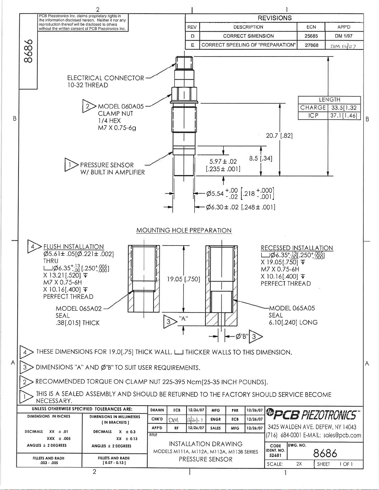
Model 060A03 Clamp nut, 5/16-24-2A thd, 1/4" hex, stainless steel (1)
Model 060A05 Clamp nut M7 x 0.75-6g thd (1)
Model 065A02 Seal ring, sensor flush mount, 0.248" OD x 0.219" ID x 0.015" thk, brass (3)
Model 065A05 Seal sleeve sensor recess mount 0.248" OD x 0.221" ID x 0.240" thk 17-4 (1)
Entered: AP Engineer: MJK Sales: KWW
Date: 3/19/2013 Date: 3/19/2013 Date: 3/19/2013 Date: 3/19/2013
Spec Number:
Phone: 716-684-0001
3425 Walden Avenue, Depew, NY 14043
Fax: 716-684-0987
E-Mail: info@pcb.com

 Loading...