

PBU 56381408, 56381409 Operator's Manual
Propane
Floor Burnisher
Equipment with Dust Control
Operator's Manual / Manuel d'utilisation / Libro de Instrucciones
Models: 56381408 (21KBCATCLDC), 56381409 (27KBCATCLDC)
READ THIS BOOK
LEA ESTE MANUAL
LISEZ CE MANUEL
This book has important information for the use and safe operation of this machine. Failure to read this
book prior to operating or attempting any service or maintenance procedure to your machine could
result in injury to you or to other personnel; damage to the machine or to other property could occur as
well. You must have training in the operation of this machine before using it. If your operator(s) cannot
read this manual, have it explained fully before attempting to operate this machine.
All directions given in this book are as seen from the operator’s position at the rear of the machine.
EN
ES
FR
English (A-2 - A-15)
Español (B-2 - B-15)
Français (C-2 - C-15)
11/10 revised 2/13 FORM NO. 56091023

A-2 / ENGLISH
TABLE OF CONTENTS
Engine Emissions and CO Safety ..................................................................A-2
Specifi cations ................................................................................................. A-8
Operator Safety Instructions ........................................................................... A-9
Introduction ................................................................................................... A-10
Propane Safety Information ...........................................................................A-11
How to Operate the Machine ........................................................................ A-12
Maintenance and Adjustments ..................................................................... A-13
Carb Gard Operation .................................................................................... A-14
Troubleshooting ............................................................................................ A-15
SECTION P - Parts Manual
Base System ......................................................................................... P-2 - P-3
Burnish System-21” ............................................................................... P-4 - P-5
Burnish System-27” ............................................................................... P-6 - P-7
Decal System ........................................................................................ P-8 - P-9
Electrical System ................................................................................P-10 - P-11
Engine System .................................................................................. P-12 - P-13
Engine Assembly ............................................................................... P-14 - P-15
Wiring Diagram .................................................................................. P-16 - P-17
DANGER!
* If you do not understand any part of the warnings or guidelines regarding
how to determine whether or not you have “Adequate” ventilation, then you
MUST contact an industrial hygienist, workplace safety expert or other safety
professional to determine the appropriate recommendations and standards
that apply to the environment in which this product is to be used.
* Only use indoors when adequate ventilation is provided, a personal carbon
monoxide (CO) detector is used and when a second person has been
instructed to look after you.
It is the owner/operator’s responsibility to ensure that an air exchange blower either of positive or negative pressure is used in any location where
a propane fl oor care machine is being operated to support a suffi cient fresh air supply to the operator during use of such a machine. OSHA
and other County, State, or Federal Agencies publish guidelines for safe machine usage regarding exhaust emissions and CO exposure in the
workplace. Failure on the part of the owner/operator to ensure that a propane fl oor care machine is operated safely in accordance with OSHA or
local state indoor air quality guidelines in a given location may lead to injury, sickness or even loss of life. To be completely aware of what local
authorities may require, contact the Fire Marshal of your community.
This Owner’s Manual/Safety Procedures Guide has been prepared for the promotion of educational purposes only and does not claim or assume
any responsibility for the operator’s actions or safety.
ENGINE EMISSIONS AND CO SAFETY
The purpose of this document is to provide information on:
· The potential effects of CO exposure;
· The methods to reduce the risk of CO poisoning;
· The methods used to determine the amount of potential exposure to CO produced by equipment.
DANGER!
All LPG (Liquid Propane Gas) powered engines, including this engine, produce Carbon Monoxide (CO). It is a LETHAL POISON that is a
colorless, odorless, tasteless, and non-irritating gas. It is produced by incomplete combustion of carbonaceous material such as propane (LPG).
Failure to provide for proper venting of CO produced during the operation of combustion powered engines may result in SERIOUS INJURY OR
DEATH to the operator and those in the contaminated area.
The effects of CO can be experienced at different exposure levels, depending on the health of the individual. Conditions that affect the tolerance of
the individual are smoking, age, temperature, humidity, and other conditions.
A-2 - FORM NO. 56091023 - PBU Propane Burnisher with Dust Control
revised 3/11

ENGLISH / A-3
WARNING!
Read and understand The Operators Manual completely before using this machine
This document explains how CO produced can be managed to reduce the risk of carbon monoxide poisoning.
All distributors, owners, and operators should be aware of the potential effects of CO and the methods used to prevent over exposure.
We are dedicated to our customers, their safety, and providing information, services, and products that meet those needs.
WARNING!
The Products sold with this Manual contain or may contain chemicals that are known to certain governments (such as the State of California, as
identifi ed in its Proposition 65 Regulatory Warning Law) to cause cancer, birth defects or other reproductive harm. In certain locations (including
the State of California) purchasers of these Products that place them in service at an employment job site or a publicly accessible space are
required by regulation to make certain notices, warnings or disclosures regarding the chemicals that are or may be contained in the Products at
or about such work sites. It is the purchaser’s responsibility to know the content of, and to comply with, any laws and regulations relating to the
use of these Products in such environments. The Manufacturer disclaims any responsibility to advise purchasers of any specifi c requirements that
may be applicable to the use of the Products in such environments.
DOCUMENT OVERVIEW
The information provided in the following overview has been condensed to provide the reader with a summary of the material presented.
Potential Effects of CO Exposure
• Work place occupational exposure guidelines for CO exposure limits vary substantially from region to region. For example, the (OSHA)
Permissible Exposure Limit (PEL) for CO is 50 ppm, as an 8-hour time weighted average (TWA); however, some countries have adopted the
ACGIH Threshold Limit Value (TLV) of 25 ppm CO. Some states (such as Minnesota) enforce a TWA PEL of 35 ppm CO, with an allowable
ceiling of no more than 200 ppm..
• Defi nition of CO effects - The toxic effects of carbon monoxide in the blood are the result of tissue hypoxia (lack of oxygen). The severity
depends on the state of activity of the individual and his tissue oxygen needs.
Methods to Reduce The Risks of CO Poisoning
• Air Exchange and CO Diffusion - CO does not mix with air on its own. Air currents can “stir” the CO and dilute the concentration values by
mixing it with the available air. When using equipment over a large area in a short time “stirring” occurs as you walk.
• Application Considerations (Burnishing versus Stripping) - When activity is concentrated to a smaller area as in a stripping application, air
“stirring” must be forced by the use of fans to reduce the risk of high concentrations of CO.
• Air Quality Monitoring – Deployment of a monitor/detector for suffi cient continuous fresh air supply is essential for the safe operation of any
equipment that has the potential to produce CO. NOTE: Dead Stop CO Detector provided in Literature Pack. Replacement part number
98758A.
• Room Size and Time Estimations - The concentration and volume of CO production, the size of the area and the amount of air exchange are
factors involved with determining safe time limits for operation in a specifi c room size.
• Maintenance of Equipment - LPG engines are dependent on engine tune up, and air fi lter replacement. Toxic CO exhaust emissions severely
increase when LPG engines run poorly or are in a poor state of maintenance. Follow the recommended Maintenance Schedule for the
engine.
• Safety Equipment Available. - Envirogard automated fuel to air ratio monitoring and regulation providing an optimum combustion, catalytic
converter muffl er to scrub CO, Hydrocarbons (HC), and Oxides of Nitrogen (NOx) from the engine exhaust providing the lowest possible
emissions, high cubic feet per minute (CFM) fans (forced fresh air mixing), and digital combustion analyzers for tail pipe emissions
monitoring.
revised 3/11
FORM NO. 56091023 - PBU Propane Burnisher with Dust Control - A-3

A-4 / ENGLISH
ENGINE EMISSIONS AND CO SAFETY
Potential Effects of CO Exposure
· Work place/industry guidelines for CO exposure limits
· Defi nition of CO effects
Work place/industry guidelines for CO exposure limits
Limits for permissible exposure to CO vary substantially from region to region. City, State, and Industry requirements should be consulted prior to
use of any equipment.
The current Occupational Safety and Health Administration (OSHA) Permissible Exposure Limit (PEL) for CO is 50 ppm, as an 8-hour time
weighted average (TWA). This is computed by making measurements at intervals over 8 hours, then adding the sums of the concentrations and
the intervals, and dividing by 8 hours. For example:
Time Interval PPM
8:00-9:00 1 HR 100
9:00-10:00 1 HR 25
10:00-11:00 1 HR 25
11:00-12:00 1 HR 50
12:00-1:00 1 HR 50 Total 400ppm/8HR=50ppm TWA
1:00-2:00 1 HR 50
2:00-3:00 1 HR 50
3:00-4:00 1 HR 50
Total time interval and PPM 8 HR Total ppm = 400k
The current National Institute for Occupational Health and Safety (NIOSH), immediately dangerous to life and health concentration (IDLH)
recommended level for CO is 1,200 ppm. NIOSH defi nes the IDLH exposure level as the concentration that could result in irreversible health
effects or death, or prevent escape from the contaminated environment within 30 minutes.
Defi nition of CO effects
The toxic effects of carbon monoxide in the blood are the result of tissue hypoxia (lack of oxygen). carbon monoxide combines with hemoglobin
to form carboxyhemoglobin. Since CO and oxygen react with the same group in the hemoglobin molecule, carboxyhemoglobin is incapable of
carrying Oxygen. The affi nity of hemoglobin for CO is 200 to 240 times greater than for oxygen. The extent of saturation of hemoglobin with CO
depends on the concentration of the gas, the quantity of inspired air and on the time of exposure. The severity depends on the state of activity of
the individual and his tissue oxygen needs.
According to Harrison’s Principles of Internal Medicine 7th edition, no symptoms will develop at a concentration of 0.01% CO (100ppm) in
inspired air, since this will not raise blood saturation above 10 %. Exposure to 0.05% (500ppm) for 1 hour during light activity will produce a
blood concentration of 20% carboxyhemoglobin and result in a mild or throbbing headache. Greater activity or longer exposure causes a blood
saturation of 30 to 50 %. At this point head ache, irritability, confusion, dizziness, visual disturbance, nausea, vomiting, and fainting can be
experienced. Exposure for one hour to concentrations of 0.1% (1000ppm) in inspired air the blood will contain 50 to 80% carboxyhemoglobin
which results in coma, convulsions, respiratory failure and death. On inhalation of high concentrations of CO, saturation of the blood proceeds so
rapidly that unconsciousness may occur suddenly without warning.
AIR QUALITY MONITORING
WARNING!
Deployment of a monitor/detector is essential for the safe operation of any equipment that has the potential to produce CO. CO sensors/detectors became available on the mass
market around 1978. At present several brands sell in the fi fty-dollar range. The main differences between the technologies involved are battery or electric and Semiconductor or
Biomimetic types. Detectors for carbon monoxide (CO) are manufactured and marketed for use in either the home or occupational industrial settings. The detectors for home use
are devices that will sound an alarm before CO concentrations in the home become hazardous. There is an Underwriters Laboratories, Inc., performance standard (UL 2034) for
residential CO detectors. Detectors currently available on the market are battery-powered, wall mount, Operator worn portable personal protective, plug-in, or hard-wired. Some
models incorporate a visual display of the parts per million (ppm) concentration of CO present in the home. For more information on CO detectors for home use, call the Consumer
Product Safety Commission Hotline at 1-800-638-2772. CO detectors for use in residential settings are not designed for use in typical workplace settings. Monitoring requirements in
an occupational setting are different from monitoring requirements in the home. In the workplace, it is frequently necessary to monitor a worker’s exposure to carbon monoxide over an
entire work shift and determine the time-weighted average (TWA) concentration of the exposure. It may also be necessary to have carbon monoxide monitors with alarm capabilities
in the workplace. The direct-reading instruments are frequently equipped with audio and/or visual alarms and may be used for area and/or personal exposure monitoring. Some have
microprocessors and memory for storing CO concentration readings taken during the day. It is signifi cant to note that some of the devices mentioned for workplace CO monitoring are
not capable of monitoring TWAs, and not all are equipped with alarms. The appropriate personal protective monitor must be chosen on an application-by-application basis. For more
information on the availability of workplace CO monitors or their application, call the National Institute for Occupational Safety and Health at 1-800-35-NIOSH (1-800-356-4674).
A-4 - FORM NO. 56091023 - PBU Propane Burnisher with Dust Control
revised 3/11
ENGLISH / A-5
METHODS TO REDUCE THE RISKS OF CO POISONING
* Air Exchange and CO Diffusion
* Application Considerations (Burnishing versus Stripping)
* Air Quality Monitoring
* Room Size and Time Estimations
* Maintenance of Equipment
* Safety Equipment Available
Air Exchange and CO Diffusion
The most reliable method to prevent CO Poisoning is to ensure all the CO produced is vented outside. With wood stoves or gas heaters this is
performed with ductwork that carries the exhaust and CO outside. Non-stationary combustion type equipment must be used in such a way that CO
is not allowed to rise to a harmful or dangerous level.
CO does not readily dissipate or mix with air on its own. Air currents can “stir” the CO and dilute the concentration or ppm values by mixing it with
the available air. When using equipment over a large area in a short time “stirring” occurs as you walk, or to say it another way, your Effective
Operating Zone is large. When activity is concentrated to a smaller area as in a stripping application, the Effective Operating Zone is small, and
“stirring” must be forced by the use of fans to increase the Effective Operating Zone and reduce high concentrations of CO.
Air exchange rates (air exchange is defi ned as the exhausting of internal air to the external atmosphere), the size of the Effective Operating
Zone, amount of CO produced, level of human activity, and the duration of exposure are all factors in the determination of the production of
carboxyhemoglobin and the amount of CO blood saturation. Be sure the area in which the equipment is being used is adequately ventilated. Refer
to Minimum Recommended Dilution Ventilation Rates provided on page 7 that are defi ned by federal and state regulations and industry accepted
guidelines that are applicable.
Application considerations (Burnishing versus Stripping)
When using equipment over a large area in a short time, as in most burnishing applications, your Effective Operating Zone is large. When activity
is concentrated to a smaller area as in stripping applications, the Effective Operating Zone is small and stirring or CO mixing MUST be forced by
the use of fans to increase the Effective Operating Zone and reduce high concentrations of CO.
Caution: air mixing in itself may not be suffi cient to reduce CO to a safe level.
The Effective Operating Zone can be defi ned as the area covered in a given time.
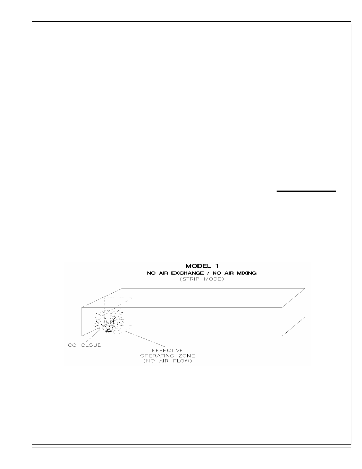
Stripping is quite a different type of operation than burnishing, and carries with it substantially more hazards, as stripping is a low movement
operation compared to burnishing (less fl oor space for the same time). As shown in Model 1, the CO concentrations rise much quicker as the
“Effective Operating Zone” is a very small area compared to the total building size.
revised 3/11
FORM NO. 56091023 - PBU Propane Burnisher with Dust Control - A-5

A-6 / ENGLISH
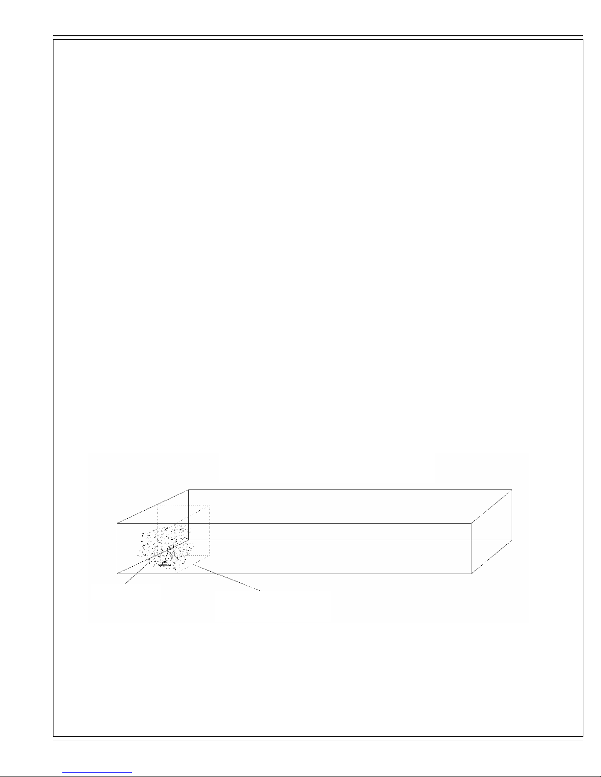
Notice the CO concentration and the Effective Operating Zone with air exchange. The CO cloud is still concentrated
in a small area. Note the “Dividing Zone” shown above, this is the line where airfl ow changes direction. In Model 2, air
changes are cut in ½ as little or no CO crosses the Dividing Zone to be exhausted.
Notice the CO concentration and the Effective Operating Zone (Expanded to the Dividing zone) with air exchange and forced air mixing. The CO
cloud is still concentrated on one side of the Dividing zone. Note the “Dividing Zone” shown above, this is the line where airfl ow changes direction.
In Model 3, air changes are cut in ½ as little or no CO crosses the Dividing Zone to be exhausted.
Notice the CO concentration and the Effective Operating Zone (Expanded through the Dividing zone to the second vent) with air exchange and
forced air mixing through the dividing Zone. The CO cloud is diluted with the available air in the building. Note the “Dividing Zone” shown above,
this is the line where airfl ow changes direction. In Model 4, air changes are full as forced air mixing has moved and mixed the CO between all air
zones.
A-6 - FORM NO. 56091023 - PBU Propane Burnisher with Dust Control
ENGLISH / A-7
MINIMUM RECOMMENDED DILUTION VENTILATION RATES FOR CARBON MONOXIDE
EXPOSURE CONTROL
PROPANE-POWERED PBU FLOOR BURNISHER NILFISK-ADVANCE, INC.
Machine & Environment
See note 7
Machines without catalytic
converter; Moderate air
mixing
Machines with catalytic
converter; Moderate air
mixing
Machines without catalytic
converter; Poor air mixing
Machines with catalytic
converter; Poor air mixing
Notes:
1 Abbreviations:
“CO” means carbon monoxide
“CO2” means carbon dioxide
“CFM” means cubic feet per minute
“PEL” means Permissible Exposure Limit. (The total exposure limit you can breathe during an eight hour period.) The PELs and TLVs shown are time-weighted average
concentrations.
“NIOSH REL” means National Institute for Occupation Safety and Health Recommended Exposure Limit.
“ACGIH TLV” means American Conference of Governmental Industrial Hygienists Threshold Limit Value. Note that some countries and provinces, such as The Ontario Ministry
of Labour reference the ACGIH TLV for CO as their occupational exposure limit.
2 These calculated ratios are based on the tailpipe emissions (see text). The ratio has been multiplied by 3 to account for the three carbons in each molecule of propane.
3 The air mixing factor, K, varies from 1 to 3, depending on the effi ciency of air mixing.
4 It is prudent to set the K factor at 3 for rooms with poor air mixing or where the equipment is used in one area for longer than usual, such as during stripping.
5 The dilution air recommendations are minimum outside air guidelines. Real-time personnel exposure monitoring should be performed using direct sensing CO monitors with
alarms in order to ensure that the fl oor burnisher is adequately tuned and that suffi cient dilution ventilation is being provided in all of the areas in which the burnisher will be used.
It would be advisable to consult an experienced occupational health & safety adviser, such as an industrial hygienist for special situations.
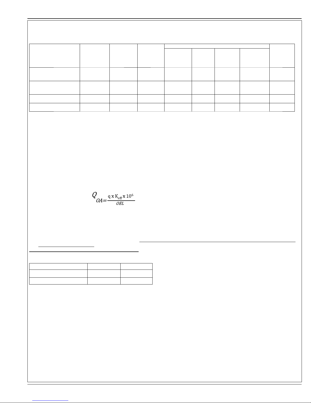
The dilution ventilation equation is:
Propane Fuel
Consumption
(lbs/hour)
3.65 0.304 1.5 326 465 465 651
3.65 0.216 1.5 232 331 331 463
3.65 0.304 3.0 651 930 930 1302
3.65 0.216 3.0 463 662 662 926
Calculated
CO
Generation
Rate (CFM)
Air Mixing
Factor K
(see Notes 3
and 4)
Dilution Ventilation Requirement, CFM (see Note 5)
Federal
OSHA PEL
(50 ppm CO)
NIOSH
REL (35
ppm CO)
Minnesota
OSHA PEL
(35 ppm
CO)
ACGIH TLV (25
ppm CO)
Comment
See Notes
4 & 5
See Notes
4 & 5
See Notes
4 & 5
See Notes
4 & 5
Where:
Q
= Volumetric fl ow rate for outside dilution air, in CFM
OA
q = Generation rate for contaminant (CO), in CFM
OEL = Occupational Exposure Limit (see Table for PEL, TLV, etcetera)
K
= A mixing factor to account for incomplete or poor delivery of dilution air (OA) to occupants. For example, a K
eff
operated in crowded spaces with tight partitions, walls or barriers and poor air supply and return locations (AIHA, 2003). A K
References
AIHA (2003) “General Methods for the Control of Airborne Hazards,” The Occupational Environment – Its Evaluation and Control, Second Edition, American Industrial Hygiene
Association, Fairfax, VA, pp. 829-846.
6 In some cases, it may be necessary to measure carbon dioxide (CO2) concentrations, especially if the background CO2 concentration already present in the room is expected to
be elevated prior to use of the burnisher.
7 See table below for model identifi cation with and without Catalytic Convertor option:
Model 21KBCATCLDC 27KBCATCLDC
Part Number
Catalytic Converter Yes
56381408 56381409
Yes
value of 3.0 is consistent with a point source of contaminants
eff
of 1.0 indicates ideal ventilation mixing effi ciency.
eff
revised 3/11
FORM NO. 56091023 - PBU Propane Burnisher with Dust Control - A-7

A-8 / ENGLISH
MAINTENANCE OF EQUIPMENT
WARNING!
The proper maintenance of equipment is vital to safe operation. LPG engines are dependent on engine tune up, and air fi lter replacement. CO
concentration (production) skyrockets when the air to fuel ratio becomes fuel rich. Follow the recommended Maintenance Schedule for the engine
found in the Engine Operator/Owner Manual as well as the Maintenance And Adjustments schedule found in the Propane Floor Equipment
Operator’s Manual that were supplied with the equipment.
CO SAFETY EQUIPMENT AVAILABLE BY MANUFACTURER
Carb Gard automated emissions monitoring will shut down the engine when high emissions are detected.•
Three-way type catalytic converter to scrub CO, Hydro Carbons (HC), and Nitrides of Oxygen (NOx) from the engine exhaust providing the lowest possible •
emissions
NOTE: Dead Stop CO Detector provided in Literature Pack. Replacement part number 98758A.•
CO SAFETY EQUIPMENT AVAILABLE ON THE MARKET
Positive or negative pressure high volume ventilation blower capable of exchanging complete room air volume to maintain CO levels below OSHA exposure •
limits.
Digital combustion analyzers for tail pipe emissions monitoring•
OSHA Approved CO Monitor•
SPECIFICATIONS:
Model
Part Number
Pad Size
Engine
Catalytic Muffl er
Carb Gard
Clutch
Pad Speed
Propane Tank
Auto Fuel Shutoff
Low Oil Shutdown
Hour Meter
Sound Pressure (ISO 11201)
Productivity Rate
Agency Approvals
CARB Certifi ed
(California Air Resource Board)
Weight
Length
Width
Height
Warranty
20 lb. (9.1 kg) Capacity, 80% Safety fi ll 20 lb. (9.1 kg) Capacity, 80% Safety fi ll
EPA plus UL Approved Propane Components EPA plus UL Approved Propane Components
21KBCATCLDC 27KBCATCLDC
56381408 56381409
21” (53 CM) 27” ( CM)
603CC KAWASAKI 603CC KAWASAKI
Yes Yes
Yes Yes
Centrifugal Centrifugal
1750 RPM 1250 RPM
Yes Yes
Yes Yes
Yes Yes
87 dB LpA, 3dB KpA 87 dB LpA, 3dB KpA
2
25,000 ft
/hr (2,322 m2/hr) 33,000 ft2/hr (3,066 m2/hr)
Yes Yes
292 lbs / 132.4 kg 302 lbs / 137 kg
66” (167.4 cm) 69” (175.3 cm)
23.3” (59 cm) 29.5” (74.9 cm)
43” (109.2 cm) 43” (109.2 cm)
2 Years Parts & Labor 2 Years Parts & Labor
A-8 - FORM NO. 56091023 - PBU Propane Burnisher with Dust Control
revised 11/11

ENGLISH / A-9
OPERATOR SAFETY INSTRUCTIONS
DANGER!
Severe bodily injury or death can occur to you or other personnel if the DANGER statements found on this machine or in this Owner’s Manual are
ignored or are not adhered to. Read and observe all DANGER statements found in this Owner’s Manual and on your machine.
WARNING!
Injury can occur to you or to other personnel if the WARNING statements found on your machine or in this Owner’s Manual are ignored or are not
adhered to. Read and observe all WARNING statements found in this Owner’s Manual and on your machine.
CAUTION!
Damage can occur to the machine or to other property if the CAUTION statements found on your machine or in this Owner’s Manual are ignored
or are not adhered to. Read and observe all CAUTION statements found in this Owner’s Manual and on your machine.
DANGER!
If you do not understand any part of the warnings or guidelines regarding how to determine whether or not you have “Adequate” ventilation, then you MUST
contact an industrial hygienist, workplace safety expert or other safety professional to determine the appropriate recommendations and standards that apply
to the environment in which this product is to be used.
Only use indoors when adequate ventilation is provided, a personal carbon monoxide (CO) detector is used and when a second person has been instructed
to look after you.
Be sure the area in which the equipment is being used is adequately ventilated. Refer to Minimum Recommended Dilution Ventilation Rates provided on
page 7 that are defi ned by federal and state regulations and industry accepted guidelines that are applicable.
Before operating the machine, verify that the ventilation system in the building is on and working properly.
Failure to read the Owner’s Manual prior to operating or attempting any service or maintenance procedure to your machine could result in injury to you or to
other personnel; damage to the machine or to other property could occur as well. You must have training in the operation of this machine before using it. If
you or your operator(s) cannot read English, have this manual explained fully before attempting to operate this machine.
Parts of this machine can cause serious injury and/or damage. Do not allow contact of clothing, hair, hands, feet, or other body parts with the rotating pad.
Keep other people away from the machine while it’s in operation.
Injury to the operator or bystanders could occur if the machine’s power is on while changing the buffi ng pad or making machine adjustments. Never try to
change the buffi ng pad or attempt to make machine adjustments while the engine is running.
Cigarette lighters, pilot lights and any other source of ignition can create an explosion if it comes in contact with propane. Propane is a highly fl ammable fuel.
All sources of ignition should be extinguished or removed entirely if possible from the work area. DO NOT SMOKE in the vicinity of a propane buffer.
This machine emits carbon monoxide. Carbon monoxide poisoning could occur if the unit is used in an area with poor or inadequate ventilation. Operate
machine in a well-ventilated area only. If a headache develops, shut off the machine. Have it checked for carbon monoxide emissions by a qualifi ed shop
before using it again. Also, verify that the ventilation system in the building is on and working properly.
Dangerous carbon monoxide emissions from this machine are greatly increased due to a dirty combustion air cleaner. Follow the engine’s manufacturer’s
air cleaner service instructions.
Propane is highly fl ammable. If you smell propane gas, shut off the machine and move it outside. Determine and repair the source of the leak before
restarting. NEVER vent propane gas inside a building. Disconnect the fuel line from the tank, remove the tank from the machine and then store the propane
tank in a secure storage cabinet outside the building. It is UNLAWFUL to store a propane bottle inside a building.
WARNING!
Long or continuous exposure to high noise levels may cause permanent hearing loss. Always wear hearing protection while using this machine.
Injury to the eyes and/or body can occur if protective clothing and/or equipment is not worn while using this machine. Always wear safety goggles and safety
clothing while using this machine.
Severe burn or injury could occur if you touch the hot muffl er or exhaust pipe. Do not touch the hot muffl er or exhaust pipe.
Any alterations or modifi cations of this machine could result in damage to the machine or injury to the operator or other bystanders. Alterations or
modifi cations not authorized by the manufacturer voids any and all warranties and liabilities.
To avoid injury or property damage, do not leave the machine where it can be tampered with or started by persons untrained in its operation. You must have
training in the operation of this machine before using it. DO NOT leave the machine running unattended.
Substantial damage to the fl oor, the machine, or personnel may result if the machine is operated with the pad off center, damaged or missing. Do not
operate the machine if the pad is off center, damaged or missing.
Operating a machine that has loose parts could result in injury or property damage. Do not operate this machine if there are loose parts. Inspect the
machine for loose parts frequently. This will promote safe operation and a long life for the machine.
Vibration from machinery may cause numbness or tingling of the fi ngers in certain people. Smoking, dampness, diet, and heredity may contribute to
the symptoms. Wearing warm clothing, gloves, exercising and refraining from smoking can reduce the effects of vibration. If the symptoms still persist,
discontinue operation of the machine.
revised 3/11
FORM NO. 56091023 - PBU Propane Burnisher with Dust Control - A-9

A-10 / ENGLISH
INTRODUCTION
This propane fl oor care equipment is manufactured in two basic concepts: the buffer/burnisher and the fl oor stripper. Both of these designs are
truly PORTABLE equipment. Propane buffers are best defi ned as ultra high speed buffers with the staying power to produce superior high gloss
fl oor surfaces. Upon contact with the fl oor, the buffer should always be kept moving. The speed at which you walk will determine the results that
you will obtain. Slower speeds create more heat and therefore more shine. A moderate pace is recommended for best results and safe operation.
NEVER RUN WITH THE BUFFER!! While a credible shine will still result, the danger of trying to stop the machine in an emergency situation is
unacceptable. When buffi ng, avoid loose tile, electric outlets, door thresholds and any object which may come in contact with the pad other than
the fl oor itself. REMEMBER, the pad is turning very rapidly.
Proper care and maintenance will protect your investment and keep your machine serving you for many years to come. It is essential that these
issues are closely followed:
CAUTION!
Overfi lling the propane tank is the number one cause of problems with a propane machine. This can cause the engine to run poorly or
not at all.
In addition, overfi lling allows liquid propane to enter the fuel control system, possibly ruining the lockoff/regulator assembly. This voids
the warranty on affected parts of the machine. To avoid problems, read and understand fully, the section “Filling and Storing Propane
Tanks.”
OVERHEATING is a major cause of engine failure. Keep the cooling air bonnet fi lter clean. Protect your machine; don’t allow wax dust/lint to
build up on the cooling fi ns of the engine cylinder(s). A good high pressure spray wash directed at the fi ns when the engine is cold will prevent
this from happening.
LOW OIL AND DIRTY OIL account for most of the other failures. It’s recommended to change the oil on a regular schedule, perhaps exceeding
that which is found in the engine manufacturers’ manual. Checking the oil daily, before putting the machine to work, is a good habit to get into
and could save you the downtime and expense of replacing the engine due to oil starvation. AFTER AN OIL CHANGE, MAKE SURE YOU HAVE
REPLACED THE OIL SUPPLY BEFORE RESTARTING THE ENGINE.
A-10 - FORM NO. 56091023 - PBU Propane Burnisher with Dust Control

ENGLISH / A-11
PROPANE SAFETY INFORMATION
Facts About LP Gas - Propane
As a fuel, Propane gas is unmatched for both safety and dependability. It has been used as a domestic household fuel for over half a century, and for over
thirty years as an internal combustion engine fuel. Propane is a highly fl ammable fuel that is contained under pressure as a liquid. Vaporized gas has a similar
explosive force to gasoline and mixtures as low as 2% LP Gas to air may be ignited in a closed environment. Care should be exercised to avoid escaping vapor
as it can freeze skin and cause frost bite. Vaporized fuel is heavier than air and will collect in the lowest confi ned space available.
Facts About Propane Tanks
Propane tanks are constructed according to ASME or Federal DOT #4ET20 pressure safety codes. Including the tank, all valves and fi ttings are UL Listed.
Propane gas is noncorrosive and will not rust the inside of a tank. Should the tank exterior become damaged or rusted, discontinue use. DO NOT tamper with
tank gauges or safety relief valves. NEVER use a tank not intended for use with a propane buffer. DO NOT substitute tanks that are used with a barbecue grill,
etc. We recommend having propane tanks tested once a year by an authorized National LP Gas Association sanctioned propane dealer.
The fuel tank is supplied directly from the manufacturer and is void of fuel. This tank must be purged at the time of the fi rst fi ll. Local fuel vendors should be
familiar with this operation and will provide this service.
Recommended Purge Procedures
How to purge new LP-Gas Buffer cylinders equipped with the Overfi ll Prevention Device:
New containers may contain vapor, air, or other contaminants. It is essential that these be removed before fi lling the container and placing it into service. Air
in the container will cause abnormally high pressure, with the result that the pressure relief valve may open. Air in the system is also likely to cause lean
mixture, making ignition diffi cult. If a cylinder is suspected of being depressurized or open to the atmosphere for a period of time, it must be re-purged as if it
were a new container.
To purge a container, the following steps should be taken.
Purging of containers should be performed in an approved area (see NFPA #5 8) using NPGA #13 3.89(a) procedure.
1. Determine if the container pressure is zero. Should the cylinder contain only pressurized air, the air may be vented directly to the
atmosphere through the service valve using an adapter and the outage valve.
2. Pressurize the container to approximately 15 psig with LP-gas vapor. Never purge with liquid LP-gas! To do so will cause the moisture vapor
to chill and remain in the cylinder. LP gas liquid also expands 270 times to vapor making the purge process ineffective. Use LP-gas vapor only!
3. Make the connection to the quick coupler (A purge manifold system is most effective). Fully open the cylinder service valve as well as the
outage valve. Vent to a safe atmosphere. A vent stack is recommended.
4. On Overfi ll Prevention Device cylinders, the purge time is increased as a result of the new valve design. Opening the outage valve will help
improve the speed of the purge.
5. Repeat #3 and #4 for a total of FIVE purges.
6. Repressurize the container with odorized LP-gas vapor to 15 psig.
7. The container is now ready to be fi lled with LP-gas.
8. Once fi lled, check all fi ttings and tank openings for leaks using an approved leak detector solution.
9. The container is now ready to be placed in service. Add DOT and OSHA labels.
Symptoms of a non-purge cylinder:
Relief valve opens due to over pressurized cylinder creating hazardous situation.
Moisture in the cylinder.
Buffer operates initially but shuts down when fuel mixture becomes too lean.
Refi lling & Storing Propane Tanks
The NFPA Technical Committee prohibits the storage of such containers in buildings. There are few exceptions to this rule. In other words, propane tanks should
NOT be stored in buildings used by the public or frequented by anyone passing through or who is working in the building. Full or empty, never leave tanks in small
enclosed areas. The tank(s) must be in a secure, tamper-proof storage enclosure that provides safety from accident or vandalism. PROPANE TANKS SHOULD
ALWAYS BE TRANSPORTED, INSTALLED AND USED IN AN UPRIGHT POSITION.
OVERFILLING PROPANE TANKS IS HAZARDOUS.
The tank should NEVER be completely fi lled with liquid propane. 80% of the total tank volume is to be considered at ALL times as full. EXPANSION MUST BE
ALLOWED FOR. Propane Buffer tanks are equipped with a fi xed liquid level gauge which contacts the liquid level at 80% of container capacity, allowing 20%
for expansion. The top part of this device must be unscrewed counterclockwise so that vapor can escape through the small hole it its side, as the tank is refi lled.
When the escaping vapor starts to give way to liquid, the device must be quickly closed and the propane nozzle turned off.
**IMPORTANT** The engine and the fuel system on your fl oor care machine are designed to run on fuel vapor, not fuel liquid. Overfi lling the propane
tank will result in damaging the lockoff and/or regulator. This will VOID the WARRANTY on these components.
FORM NO. 56091023 - PBU Propane Burnisher with Dust Control - A-11

A-12 / ENGLISH
HOW TO OPERATE THE MACHINE
Preparing The Machine For Use
BEFORE using any type of powered equipment, proper safety dictates you should visually inspect it.
1. Adjusting the Handle -
(a) Adjust the handle to a comfortable height by pulling outward on the two spring-loaded pins on each side of the handle.
(b) While holding the pins out, adjust the handle to the height desired.
(c) Release the pins so that they insert themselves into the locked positions. NOTE: It may be easier to stand to one side of the handle and
reach across to the other side to make the adjustment.
2. Bonnet Filter- Make sure the bonnet air fi lter atop the engine is clean. It should be changed hourly and thoroughly cleaned before reuse.
3. Oil Level -
(a) Check the engine OIL LEVEL.
(b) With the buffer sitting in a level position, unscrew the yellow oil fi ller cap, pull out, and wipe dipstick off with a clean cloth.
(c) Insert the dipstick into the tube, but DO NOT screw it back in.
(d) Pull the dipstick out and check the oil level making sure the oil level is in the operating range (grid area) shown on the dipstick. If the oil
level is in the “ADD” range, add enough engine oil to bring the oil level to the operating range. NOTE: NEVER overfi ll the engine oil as this
can lead to irreparable damage to the engine.
4. Filling the Tank- Fill the tank following the instructions as given under the previous heading: “Refi lling And Storing Propane Tanks.” In
addition, if your buffer came with an “80% Safety Fill Tank” then it should ONLY be fi lled through the threaded valve with the larger diameter
that is covered by a yellow cap to ensure a “Full” level that is safe.
5. Pad and Pad Holder -
Inspect the condition of the pad and pad holder.
(a) Adjust handle to it’s extreme upright position. (NOTE: Pins should be in the hole marked “TILTBACK”).
(b) Grabbing the handle with both hands and placing your foot on the back deck of the burnisher for stability, pull back on the handle and tilt
the machine back.
(c) Let the handle rest on the fl oor to hold the machine in the upright position.
(d) Go to the pad side of the machine for inspection and/or replacement. Is there a pad? Is it properly attached? What is it’s condition?
Ensure the pad is clean and has at least a thickness of 1/3 of an inch. Always turn off the engine before checking the pad.
6. Tank and Fuel Lines - The tank has already been covered but do the fuel lines show any sign of wear and tear, such as cracks or any
corrosion? Screw the brass fuel line fi tting onto the tank service valve, hand tight only. This connection MUST be secure because the
service valve has a safety valve inside it which will only open if the brass fuel line fi tting is COMPLETELY seated into the service valve.
7. Dust Containment Area -
Check the dust containment area and make sure that it is clean. This is the area underneath the propane tank.
(a) Remove the propane tank and then lift the black lid and locate the automotive-type fi lter.
(b) Inspect the fi lter. Is it dirty? Does it need to be cleaned or replaced? Make sure that the trough - that is outside of and below the level of
the fi lter - is clean.
8. Dust Skirt - Check out the condition of the skirt that surrounds the deck. Is it in good condition? What is the condition of the rubber boot
that connects the skirt to the rear part of the deck? Replace the boot if it is ripped or torn.
Starting the Engine
1. Open the service valve on the propane tank by turning counterclockwise, about one and a half turns.
2. Ensure the buffer is tilted back so that the pad is off the fl oor on all machines without a clutch.
3. The engine is designed to be started with the throttle in the idle position. This creates a vacuum necessary to open the lock-off valve inside
the regulator. Movement of the throttle lever will keep the lock-off valve from opening and the engine from getting fuel so the engine will not
start. Proper maintenance will insure easy starting.
4. Engage starter for a MAXIMUM of 5 to 6 seconds or until the engine fi res. Serious starter damage will result if this is exceeded and the
warranty may not apply.
5. Operate the engine at half throttle for approximately two minutes for proper warm-up. Then advance to full throttle for best results.
NOTE: If the engine refuses to start, see the Trouble Shooting Guide.
Stopping The Engine
1. Close the service valve on the propane tank, by turning clockwise. This consumes all of the propane that is still in the fuel system.
2. ALWAYS allow the engine to run until it stops from lack of fuel, and then shut off the key switch. ** ONLY IN AN EMERGENCY should the “kill
switch” on buffer be used.
3. Disconnect the fuel line from the tank.
4. REMEMBER, when you are fi nished with the machine, store the propane tank outside the building, in a safe place away from heat or direct
sunlight.
A-12 - FORM NO. 56091023 - PBU Propane Burnisher with Dust Control

ENGLISH / A-13
MAINTENANCE AND ADJUSTMENTS
Emission Control Information
To protect the environment in which we will live, the manufacturer has incorporated crankcase emission (1) and exhaust emission (2) control systems (EM) in
compliance with applicable regulations of the United States Environmental Protection Agency and California Air Resources Board.
1. Crankcase Emission Control System. A sealed-type crankcase emission control system is used to eliminate blow-by gases. The blow-by gases are led
to the breather chamber through the crankcase. Then, it is led to the air cleaner. Oil is separated from the gases while passing through the inside of the
breather chamber from the crankcase, and then returned back to the bottom of crankcase.
2. Exhaust Emission Control System. The exhaust emission control system applied to this engine consists of a carburetor and an ignition system having
optimum ignition timing characteristics. The carburetor has been calibrated to provide lean air/fuel mixture characteristics and optimum fuel economy with a
suitable air cleaner and exhaust system.
Tampering w/Emission Control System Prohibited
Federal law and California State law prohibits the following acts or the causing thereof: (1) the removal or rendering inoperative by any person other than for
purposes of maintenance, repair, or replacement, of any device or element of design incorporated into any new engine for the purpose of emission control prior to
its sale or delivery to the ultimate purchaser or while it is in use, or (2) the use of the engine after such device or element of design has been removed or rendered
inoperative by any person.
Among those acts presumed to constitute tampering are the acts listed below:
Do not tamper with the original emission related part.
>Carburetor and internal parts
>Spark plugs (Only OEM quality and part number spark plugs may be used to replace the OEM spark plug the machine was equipped with from the factory)
>Magneto or electronic ignition system
>Air cleaner elements (Only OEM quality and part number air fi lters may be used to replace the OEM air fi lter the machine was equipped with from the factory)
>Crankcase
>Cylinder heads
>Breather chamber and internal parts
>Intake pipe and tube
General Maintenance and Adjustments
1. Fuel Control System - To ensure personal safety, adjustments should ONLY be made by a qualifi ed LPG system technician or an authorized service center,
using an exhaust gas analyzer. Do not operate the machine if carbon monoxide levels exceed OSHA standards.
2. Pad Replacement-
(a) Adjust handle to its extreme upright position (Note: Pins should be in the hole marked “TILTBACK”).
(b) Grabbing the handle with both hands and placing your foot on the back deck of the burnisher for stability, pull back on the handle and tilt the machine
back.
(c) Let the handle rest on the fl oor to hold the machine in the upright position.
(d) Now move to the pad side of the machine.
(e) Grab the metal clip, which is located in the white center-lock device, between the thumb and index fi nger and squeeze. This allows the pad retainer to
“pop” off.
(f) Remove the old pad.
(g) Install the new pad by carefully centering it against the “harpoon hook” plastic gripper.
(h) Replace the pad retainer by snapping it back in place (Note: The center-lock ring should “snap” twice).
(i) Check the rotation of the pad driver. Eccentricity of the pad should not exceed 1/4 of an inch.
3. Belt Replacement -
(a) Tilt the machine back as you would to replace the pad.
(b) Using a 3/4” open-end wrench, secure the shaft from the engine side of the deck and spin off the pad driver to remove it.
(c) Use the same 3/4” wrench to release tension on the belt by rotating the Lovejoy tensioner towards the belt.
(d) Release the Lovejoy tensioner and carefully remove the belt from the engine clutch and the drive pulley.
(e) Now install the new belt onto the clutch and pulley and use the wrench to again release the tension on the Lovejoy tensioner until the belt is in position.
(f) Release the Lovejoy tensioner to apply tension to the belt. (Note: the arrow on the Lovejoy tensioner should be pointing towards 30°. If it is not, reset
the tensioner by fi rst loosening and then re-tightening the bolt that holds the tensioner to the deck).
(g) Reinstall the pad driver.
4. Changing the Engine Oil -
WARNING!
Changing the oil to a non OEM approved viscosity may change the emission output of the engine!
(a) Start and warm up the engine so the oil will drain easily.
(b) Stop the engine.
(c) Place the buffer in a level position.
(d) Pull the clear plastic tube out of it’s holder and rotate the tube so that it can drain into a container.
(e) Grab the 1/4-turn quick release oil drain and rotate counterclockwise. This will allow the engine oil to drain.
(f) After draining is complete, rotate the quick release 1/4-turn clockwise to close and store the clear plastic tube in it’s upright position.
FORM NO. 56091023 - PBU Propane Burnisher with Dust Control - A-13

A-14 / ENGLISH
MAINTENANCE AND ADJUSTMENTS
5. Changing the Oil Filter -
(a) Using either a strap wrench or an oil fi lter wrench, rotate the oil fi lter counterclockwise. Note: Before unscrewing the oil fi lter, place a suitable container
beneath the oil drip tray to catch the oil that is from the fi lter or any oil passages in the engine.
(b) Clean the oil fi lter base on the engine.
(c) Apply a thin coat of engine oil to the seal of the oil fi lter.
(d) Install the fi lter by turning it clockwise until the seal contacts the mounting surface of the engine.
(e) Then turn the fi lter by hand(s) 3/4 turn more.
(f) Run the engine at a slow idle speed for 2 minutes and check the oil fi lter and drain line for leaks.
6. Adjusting Pad Pressure -
(a) Tilt the machine back as you would to change the pad.
(b) To increase the pad pressure, move the wheels towards the rear of the machine. To do this, disconnect the hairpin from the clevis pin. Slide the clevis
pin out and move the wheel to the back hole in the wheel caster. Reinsert the clevis pin and attach the hairpin.
(c) To decrease pad pressure, use the same procedure and move the wheel towards the front of the machine.
Recommended 8 Hour Break In (50 hour there after) Maintenance Items -
>Change engine oil.
>Check pad driver for loose parts.
>Check belt for wear or slippage.
>Check engine pulley for tightness.
>Check wheel bolts.
>Check engine mount bolts.
>Check handle bolts.
>Check for leakage of engine oil at the various seals.
Recommended Oil Change Intervals
Do not exceed the oil change interval. Oil changes more frequent than 50 hours will give even longer engine life. In any case, always use 30HD or 10W30 engine
oil with all of the following API ratings: SJ or higher. Make sure the oil level is maintained at the “FULL” level.
Recommended 100 Hour Maintenance
The dust control fi lter must be changed every 100 hours.
Change the oil fi lter every 100 hours of operation.
Recommended 200 Hour Maintenance
Return machine to authorized service center for overall checkup.
The engine air intake fi lter must be changed every 200 hours.
>Check engine valve adjustment
CARB GARD OPERATION
Carb Gard is a warning device to alert the operator that the engine needs to be serviced.
1. Upon starting the engine, the GREEN “Alert” LED will begin fl ashing. It will continue fl ashing for 3 minutes. This allows the engine and the
oxygen sensor (mounted in the exhaust manifold) enough time to warm up. During this time, it is okay to operate the burnisher.
2. After 3 minutes, the Alert LED will stop fl ashing.
(a) If the engine is idling, then the YELLOW “Idle” LED will begin fl ashing. This allows the engine to idle for up to 2 minutes.
(b) After 2 minutes, the engine will shut down and the idle LED will remain solid to notify the operator why the machine shut down. (Note: If
this occurs, simply turn the key switch to OFF. This will reset the Carb Gard. Restart the engine normally to continue operation).
(c) If at any time before the 2 minute countdown, the engine is revved up to full throttle, the LED will stop fl ashing and the Carb Gard will
being monitoring the oxygen sensor.
(d) If the engine is allowed to slow back down to the idle position, the idle LED will again start fl ashing for another 2 minutes.
NOTE: Every time the engine is revved up and allowed to slow down, the 2 minute countdown restarts itself.
3. Once the engine is revved up, the Carb Gard begins monitoring the oxygen sensor for carbon monoxide (CO).
(a) If at any time during full throttle the Carb Gard senses a higher than normal CO output, it will activate the RED “Service” LED and it will
begin fl ashing.
(b) If the RED service LED fl ashes continuously for 1 minute, then the engine will shut down and the RED service LED will remain solid to
notify the operator why the engine shut down.
NOTE: Carb Gard continuously monitors CO output. If the CO output drops, the service LED will stop fl ashing. If the CO output rises, it will
start fl ashing again. ONLY after it continuously fl ashes for 1 minute will it shut down the engine.
A-14 - FORM NO. 56091023 - PBU Propane Burnisher with Dust Control
revised 11/11

ENGLISH / A-15
TROUBLESHOOTING
When troubles occur, be sure to check the simple causes which at fi rst, may seem too obvious to be considered. For example, a starting problem
could be caused by fuel starvation due to an empty propane cylinder or an unopened service valve. If you don’t check for this, starter burnout
could result.
1. EXCESSIVE VIBRATION - Look for the following possibilities:
(a) Pad is off center. Remove and reinstall.
(b) Pad Driver is bent or cracked. (Possibly from striking a curb or bolt in the fl oor.) Replace immediately with a new part only.
(c) Bearings in Front End Assembly are worn. Place the machine on its side opposite the muffl er and dipstick. Grip Pad Driver and move
up, down and from side to side to check for slack in the bearings. If this is the case, then to effect a proper repair, the bearings should be
replaced and possibly the shaft. Contact an authorized service center.
(d) Check to see if the bolts on shaft housing are tight. Look to see if the nuts, bolts and spacers on the Flex Coupler Assembly are all in
place and tight. Contact an authorized service center.
2. ENGINE STARTS AND IDLES, BUT WILL QUIT AS THE THROTTLE IS ADVANCED - It is possible that the propane tank’s service valve
is faulty. To check for this, close the valve completely and then reopen very slowly while you listen for a “click” when the gas begins to travel
through the valve. If you hear this very slight noise, then what is happening is the valve is only partially opening. This allows enough gas
through to start and idle the engine, but not enough for full throttle operation. As the throttle is increased, allowing more air to enter the
intake, the engine will quit from fuel starvation. Call your dealer for instructions on where to have the service valve replaced. Meanwhile,
to get by, you can continue to open the service valve until you don’t hear a “click” and then the engine will run normally. IF IT DOES NOT,
contact an authorized service center.
3. THE BUFFER SEEMS TO RUN WELL BUT DIES DOWN WHEN THE PAD IS PLACED ON THE FLOOR OR SOON THEREAFTER -
Check for the same problem as in #2.
4. EXCESSIVE NOISE FROM UNDER BUFFER - If this problem has developed after use of the machine from new, then the fi rst place to check
is the Automatic Tensioner. As a new belt wears in, it naturally stretches a bit and the tensioner will begin to rattle. Place the buffer on its side
(with the muffl er down) and reset by taking up the slack in the belt and tighten the Automatic Tensioner.
5. STARTER WILL HARDLY TURN THE ENGINE OVER or THE SOLENOID JUST CLICKS ON 12 VOLT OPTION MODELS - The battery
is likely low in charge. This can be remedied by recharging the battery using a 12 volt battery charger at 4-12 amperes. The battery is
located under the frame at the rear of the buffer. The positive post is the one with the RED cable attached to it. Follow the instructions that
came with the battery charger. REMINDER: this will continue to happen unless the buffer’s engine is run for suffi cient time between starts to
recharge the battery.
6. ENGINE BACKFIRES LOUDLY AND REGULARLY SUDDENLY - Check the sparkplug boots. One of them is likely cracked, possibly due
to contacting a corner of a shelf or a door frame. Remove the sparkplug lead from the sparkplug and replace the boot with a new one. The
engine should now run normally. IF IT DOES NOT, contact an authorized service center.
FORM NO. 56091023 - PBU Propane Burnisher with Dust Control - A-15

B-2 / ESPAÑOL
LEA ESTE MANUAL
Este manual contiene información importante acerca del uso y la seguridad de la máquina. Si no lee el manual antes de utilizar su máquina o de intentar realizar
los procedimientos de reparación o mantenimiento de la misma, usted o el resto del personal podrían sufrir lesiones; asimismo, podrían producirse daños a la
máquina o a otras propiedades. Antes de utilizar la máquina, es necesario recibir la capacitación adecuada en la operación de la misma. Si el operador de la
máquina no sabe leer en inglés, explíquele el manual exhaustivamente antes de que intente utilizarla.
Todas las indicaciones incluidas en este manual se ofrecen desde la posición del operador en la parte posterior de la máquina.
ÍNDICE
Seguridad de las emisiones de los motores y el monóxido de carbono ....................... B-2
Especifi cacions de la máquina ..................................................................................... B-8
Instrucciones de seguridad para el operador ............................................................... B-9
Introducción: ............................................................................................................... B-10
Información de seguridad sobre el propano ................................................................B-11
Operación de la máquina ...........................................................................................B-12
Mantenimiento y ajustes ............................................................................................. B-13
Operación Carb Gard ................................................................................................. B-14
Resoluciòn de problemas ........................................................................................... B-15
SECCIÓN P – Libro de piezas ............................................................................P-2 - P17
PELIGRO!
* Si no entiende cualquier parte de las advertencias o los lineamientos
relacionados con cómo determinar si la ventilación es “adecuada”, DEBE
consultar a un higienista industrial, experto en seguridad en el trabajo u otro
profesional de la seguridad a fi n de determinar las recomendaciones y normas
apropiadas que correspondan al entorno donde se utilizará este producto.
* Úsela en interiores solamente si existe ventilación adecuada, si se usa un
detector personal de monóxido de carbono (CO) y si una segunda persona
tiene instrucciones de cuidarlo.
Es responsabilidad del propietario/operador asegurar que se utilice un soplador intercambiador de aire con presión positiva o negativa en un lugar
donde funcione una máquina de cuidado de suelo de propano para proporcionar un buen suministro de aire fresco para el operador durante el
uso de tal máquina. OSHA y otras Agencias Federales, Estatales y del Condado publican lineamientos para la utilización segura de máquinas
con respecto a las emisiones de escape y a la exposición a monóxido de carbono en el lugar de trabajo. Si el propietario/operador no garantiza
que una máquina de cuidados de suelo de propano funcione de manera segura de acuerdo con los lineamientos OSHA o las pautas locales,
estatales en cuanto a calidad de aire en lugares cerrados, podría resultar en lesiones, enfermedades o aún la pérdida de vida. Para conocer por
completo los requerimientos de las autoridades locales, póngase en contacto con el Jefe de Bomberos de su comunidad.
La Guía de Procedimientos de Seguridad/Manual del Propietario se ha preparado para fi nes informativos solamente y no asume responsabilidad
por las acciones o la seguridad del operador.
SEGURIDAD DE LAS EMISIONES DE LOS MOTORES Y EL MONÓXIDO DE CARBONO
El objetivo de este documento es suministrar información sobre:
Los potenciales efectos de la exposición al monóxido de carbono;
Los métodos para reducir el riesgo de envenenamiento con monóxido de carbono;
Los métodos utilizados para determinar el nivel de exposición potencial al monóxido de carbono producido por un equipo.
PELIGRO!
Todos los motores que funcionan con propano líquido (PL), incluso este motor, producen
monóxido de carbono (CO). Este VENENO MORTAL es un gas incoloro, inodoro, insípido y que no irrita. Es producto de la combustión
incompleta de un material carbonoso tal como el propano (PL).
La falta de adecuada ventilación del monóxido de carbono producido durante el funcionamiento de motores a combustión puede resultar en
LESIONES GRAVES O LA MUERTE del operador y de quienes se encuentren en el área contaminada.
Los efectos del CO se pueden sufrir a distintos niveles de exposición, dependiendo de la salud del individuo. Las condiciones que afectan la
tolerancia del individuo son fumar, la edad, la temperatura, la humedad y otras.
B-2 - FORM NO. 56091023 - PBU Propane Burnisher with Dust Control
revised 3/11

ESPAÑOL / B-3
ADVERTENCIA!
Antes de usar esta máquina debe leer y comprender totalmente el Libro de instrucciones.
Este documento explica cómo manejar el CO producido para reducir el riesgo de envenenamiento con monóxido de carbono.
Todos los distribuidores, propietarios y operadores deberán tener presentes los potenciales efectos del CO y los métodos utilizados para prevenir
la sobreexposición.
Está dedicada a sus clientes, la seguridad de los mismos, y a proporcionar información, servicios y
productos que contemplen esas necesidades.
ADVERTENCIA!
Los Productos a la venta en este Manual contienen, o pueden contener, productos químicos reconocidos por algunos gobiernos (como el Estado
de California, según lo indica en su Proposición 65, Ley de Advertencia Regulatoria) como causantes de cáncer, defectos de nacimiento u
otros daños reproductivos. En algunas jurisdicciones (incluido el Estado de California), los compradores de estos Productos que los coloquen
en servicio en un emplazamiento laboral o en un espacio de acceso público tienen la obligación regulatoria de realizar determinados avisos,
advertencias o divulgaciones respecto de los productos químicos contenidos o posiblemente contenidos en los Productos utilizados en tal lugar.
Es la responsabilidad del comprador conocer y cumplir con todas las leyes y reglamentaciones relacionadas con el uso de estos Productos en
tales entornos. El Fabricante niega toda responsabilidad de informar a los compradores sobre requisitos específi cos que pueden regir el uso de
los Productos en tales entornos.
INFORMACIÓN GENERAL DEL DOCUMENTO
La información que aparece a continuación ha sido condensada para proporcionarle al lector un resumen del material presentado.
Potenciales efectos de la exposición al monóxido de carbono
• Los lineamientos de exposición ocupacional en el lugar de trabajo referidos a los límites de exposición a CO son muy distintos según la
región. Por ejemplo, el límite de exposición permisible (PEL) de OSHA para el CO es de 50 ppm, como un promedio ponderado en el tiempo
(TWA) de 8 horas. Sin embargo, algunos países han adoptado el valor umbral límite (TLV) de 25 ppm CO de ACGIH. Algunos estados, como
Minnesota, exigen un TWA PEL de 35 ppm CO, con un techo permisible de no más de 200 ppm.
• Defi nición de los efectos del CO – Los efectos tóxicos del monóxido de carbono en la sangre son consecuencia de la hipoxia (falta de
oxígeno) de los tejidos. La gravedad depende del estado de actividad del individuo y de la necesidad de oxígeno de sus tejidos.
Métodos para reducir los riesgos de envenenamiento con CO
• Cambio de aire y difusión del CO – El monóxido de carbono no se mezcla libremente con el aire. Las corrientes de aire pueden “revolver”
el CO y diluir los valores de concentración al mezclarlo con el aire circundante. Cuando se usan equipos en un área extensa durante corto
tiempo, se “revuelve” al caminar.
• Consideraciones sobre la aplicación (Pulir o rasquetear) – Cuando la actividad se concentra en una área pequeña como en la aplicación del
rasqueteo, se debe forzar al aire a “revolverse” por medio de ventiladores para reducir el riesgo de las grandes concentraciones de CO.
• Monitoreo de calidad de aire – La utilización de un monitor/defl ector para el suministro continuo y sufi ciente de aire fresco es esencial para el
funcionamiento segura de cualquier equipo que tenga el potencial de producir monóxido de carbono. NOTA: Detector de CO (monóxido de
carbono) con detención total se suministra en Paquete de Documentación. Número de parte de reemplazo 98758A.
• Cálculo del tamaño de la habitación y del tiempo – La concentración y el volumen de producción de monóxido de carbono, el tamaño del
área y la cantidad del cambio de aire son factores que permiten determinar los límites de tiempo seguros para operar en una habitación de
un tamaño específi co.
• Mantenimiento de los equipos – El buen funcionamiento de los motores de LPG (gas de petróleo líquido) depende de un buen reajuste
del motor y del reemplazo de los fi ltros de aire. Las emisiones tóxicas de monóxido de carbono se incrementan cuando los motores LPG
funcionan de manera defi ciente o su mantenimiento no es bueno. Siga el Programa de Mantenimiento recomendado para el motor.
• Equipo de seguridad disponible. - Monitoreo y regulación automatizada de proporción de combustible en aire Envirogard con conversor
catalítico para eliminar monóxido de carbono (CO), hidrocarburos (HC) y óxidos de nitrógeno (NOx) del escape del motor suministrando
la menor cantidad de emisiones posibles, ventiladores de pies cúbicos por minuto (CFM) (mezcla de aire forzado fresco), y analizadores
digitales de combustión para monitoreo de emisiones de tubo de escape.
revised 3/11
FORM NO. 56091023 - PBU Propane Burnisher with Dust Control - B-3

B-4 / ESPAÑOL
SEGURIDAD DE LAS EMISIONES DE LOS MOTORES Y EL MONÓXIDO DE CARBONO
Potenciales efectos de la exposición al CO
Pautas para la industria / el lugar de trabajo sobre los límites de exposición al CO
Defi nición de los efectos del CO
Pautas para la industria / lugar de trabajo sobre los límites de exposición al monóxido de carbono
Los límites de la exposición permitida al monóxido de carbono varían sustancialmente de una región a otra. Antes de utilizar cualquier equipo, se deben consultar
las exigencias de la ciudad, el estado y la industria.
El límite de exposición permitido (PEL, por sus siglas en inglés) actualmente por la Administración de la Seguridad y Salud Ocupacionales de los Estados Unidos
(OSHA, por sus siglas en inglés) para el monóxido de carbono es de 50 ppm, como promedio ponderado por tiempo (TWA, por sus siglas en inglés) de 8 horas.
Esto se computa tomando mediciones a intervalos durante 8 horas, luego sumando los totales de las concentraciones y los intervalos, y dividiendo por 8 horas.
Por ejemplo:
Hora Intervalo PPM
8:00-9:00 1 HR 100
9:00-10:00 1 HR 25
10:00-11:00 1 HR 25
11:00-12:00 1 HR 50
12:00-1:00 1 HR 50 Total 400 ppm /8HR = 50 ppm TWA
1:00-2:00 1 HR 50
2:00-3:00 1 HR 50
3:00-4:00 1 HR 50
Intervalo de tiempo total y PPM 8 HR Total ppm = 400k
La concentración inmediatamente peligrosa para la vida y la salud (IDLH por sus siglas en inglés) que actualmente recomienda el Instituto Nacional de Seguridad
y Salud Ocupacional de los Estados Unidos (NIOSH, por sus siglas en inglés) para el CO es de 1,200 ppm. NIOSH defi ne el nivel de exposición IDLH como la
concentración que podría provocar la muerte o efectos irreversibles sobre la salud, o que podría impedir que una persona salga del ambiente contaminado dentro
de los 30 minutos.
Defi nición de los efectos del CO
Los efectos tóxicos del monóxido de carbono en la sangre son consecuencia de la hipoxia (falta de oxígeno) de los tejidos. El monóxido de carbono se
combina con la hemoglobina y forma carboxihemoglobina. Como el CO y el oxígeno reaccionan con el mismo grupo en la molécula de hemoglobina, la
carboxihemoglobina es incapaz de transportar oxígeno. La afi nidad de la hemoglobina con el CO es de 200 a 240 veces mayor que con el oxígeno. El grado
de saturación de la hemoglobina con CO depende de la concentración del gas, de la cantidad de aire inspirado y de la duración de la exposición. La gravedad
depende del estado de actividad del individuo y de la necesidad de oxígeno de sus tejidos.
Según la publicación de Harrison, Principios de medicina interna, 7ª edición, no se presentarán síntomas a una concentración de 0.01% CO (100ppm) en el aire
inspirado, puesto que esto no elevará la saturación en sangre por encima del 10%. La exposición a 0.05% (500ppm) durante 1 hora de actividad liviana producirá
una concentración en sangre de 20% de carboxihemoglobina que causará un dolor de cabeza leve o punzante. Mayor actividad o exposición más prolongada
produce una saturación de la sangre de 30 a 50%. En este punto se puede experimentar dolor de cabeza, irritación, confusión, mareo, disturbios visuales,
nauseas, vómitos y desmayo. Luego de estar expuesto durante una hora a concentraciones de 0.1% (1000ppm) en el aire inspirado, la sangre contiene de 50 a
80% de carboxihemoglobina ocasionando coma, convulsiones, paro respiratorio y la muerte. Si se inhalan concentraciones elevadas de CO, la saturación de la
sangre progresa con tanta rapidez que la inconsciencia puede ocurrir repentinamente y sin aviso.
CONTROL DE LA CALIDAD DEL AIRE
ADVERTENCIA!
La utilización de un monitor/detector es esencial para el funcionamiento seguro de cualquier equipo que tenga el potencial de producir monóxido de carbono.
Los sensores/detectores de monóxido de carbono salieron a la venta en el mercado alrededor de 1978. Hoy en día, se pueden encontrar diversas marcas
en el rango de los cincuenta dólares. Las principales diferencias entre las tecnologías aplicables son los tipos de semiconductores a batería o eléctricos o
biomiméticos. Detectores para monóxido de carbono (CO) son fabricados y comercializados para ser utilizados en entornos domiciliarios, laborales o industriales.
Los detectores para uso doméstico son dispositivos que activarán una alarma sonora antes de que las concentraciones de CO en el hogar se tornen peligrosas.
Hay una norma de rendimiento de Underwriters Laboratories Inc., (UL 2034) para detectores de CO residenciales. Los detectores actualmente disponibles en
el mercado son a batería, montados en pared, como parte del equipo portátil de protección personal del operador, a enchufe o por cable. Algunos modelos
incorporan un pantalla visual de la concentración de partes por millón (ppm) de CO presente en el hogar. Para obtener más información sobre los detectores
de CO para uso doméstico, llame a la línea de ayuda de la Comisión de Seguridad para Productos de Consumo al 1-800-638-2772. Los detectores de CO para
uso en entornos residenciales no están diseñados para ser usados en entornos laborales típicos. Los requerimientos de monitoreo en un entorno laboral son
diferentes de los requerimientos necesarios en el hogar. En el lugar de trabajo, es frecuentemente necesario monitorear la exposición del trabajador a monóxido
de carbono durante un turno de trabajo completo y determinar la concentración promedio ponderada en el tiempo (TWA) También puede ser necesario tener
monitores de monóxido de carbono con funciones de alarma en el lugar de trabajo. Los instrumentos de lectura directa vienen frecuentemente equipados con
alarmas sonoras y/o visuales y pueden ser utilizados para monitoreos de exposiciones en áreas o personales. Algunos tienen microprocesadores y memoria
para almacenar lecturas de concentración de CO tomadas durante el día. Es importante señalar que algunos de los dispositivos mencionados para el monitoreo
de CO en el lugar de trabajo no son capaces de monitorear TWA y no todos vienen equipados con alarmas. El monitor de protección personal adecuado debe
seleccionarse en función de cada aplicación en particular. Para obtener más información sobre la disponibilidad de monitores de CO en el lugar de trabajo o su
aplicación, llame al Instituto Nacional para la Seguridad y Salud Ocupacional al número 1-800-35-NIOSH (1-800-356-4674).
B-4 - FORM NO. 56091023 - PBU Propane Burnisher with Dust Control
revised 3/11
ESPAÑOL / B-5
MÉTODOS PARA REDUCIR LOS RIESGOS DE ENVENENAMIENTO CON CO
Cambio de aire y difusión del CO·
Consideraciones sobre la aplicación (Pulir o rasquetear)·
Control de la calidad del aire·
Cálculo del tamaño de la habitación y el tiempo·
Mantenimiento del equipo·
Equipo de seguridad disponible·
Cambio de aire y difusión del CO
El método más confi able para prevenir el envenenamiento con CO es asegurarse que todo el CO producido se ventile hacia fuera. Cuando
hay estufas a leña o calentadores a gas, esto se realiza por medio de conductos que transportan los gases y el CO al exterior. Los equipos a
combustión que no son fi jos se deben usar de manera tal que el CO no pueda alcanzar niveles nocivos o peligrosos.
El monóxido de carbono no se disipa ni se mezcla libremente con el aire. Las corrientes de aire pueden “revolver” el CO y diluir los valores de
ppm o de concentración al mezclarlo con el aire circundante. Cuando se usan equipos en un área extensa durante corto tiempo, se “revuelve”
al caminar, lo que signifi ca que la zona de operación efectiva es extensa. Cuando la actividad se concentra en una área pequeña como en una
aplicación de rasqueteo, se debe forzar al aire a “revolverse” por medio de ventiladores para aumentar la zona de operación efectiva y reducir las
grandes concentraciones de CO.
La velocidad del cambio de aire (el cambio de aire se defi ne como la extracción del aire interior a la atmósfera exterior), el tamaño de la zona de
operación efectiva, la cantidad de CO producido, el nivel de actividad humana, y la duración de la exposición son todos factores que determinan
la producción de carboxihemoglobina y el nivel de saturación de monóxido de carbono en la sangre. Asegúrese de que el área donde se usa
el equipo esté bien ventilada. Consulte las proporciones de ventilación por dilución mínimas recomendadas de la página 7 defi nidas por las
reglamentaciones federales y estatales y los lineamientos aceptados por la industria que correspondan.
Consideraciones sobre la aplicación (Pulir o rasquetear)
Cuando se usa equipo sobre un área extensa en poco tiempo, como ocurre en la mayoría de las aplicaciones de pulido, la zona de operación
efectiva es amplia. Cuando la actividad se concentra en una área pequeña como en una aplicación de rasqueteo, la zona de operación efectiva
es pequeña y se DEBE forzar al CO a mezclarse o revolverse por medio de ventiladores para aumentar la zona de operación efectiva y reducir
las grandes concentraciones de CO.
Precaución: Mezclar el aire solamente puede no ser sufi ciente para reducir el CO a un nivel seguro.
La zona de operación efectiva se puede defi nir como el área cubierta en un tiempo determinado.
El rasqueteado es un tipo de operación bastante diferente al pulido, y conlleva muchos más riesgos, ya que en relación al pulido el rasqueteado
es una operación de poco movimiento (menos superfi cie del suelo en el mismo tiempo). Como se muestra en el Modelo 1, las concentraciones de
CO aumentan más rápidamente ya que la “zona de operación efectiva” es un área muy reducida comparada al tamaño total del edifi cio.
MODELO 1
Le nube de CO
Sin cambio de aire / Sin mezcla de aire
Zona de operación efectiva
(Sin flujo de aire)
(Modo rasquetado)
revised 3/11
FORM NO. 56091023 - PBU Propane Burnisher with Dust Control - B-5
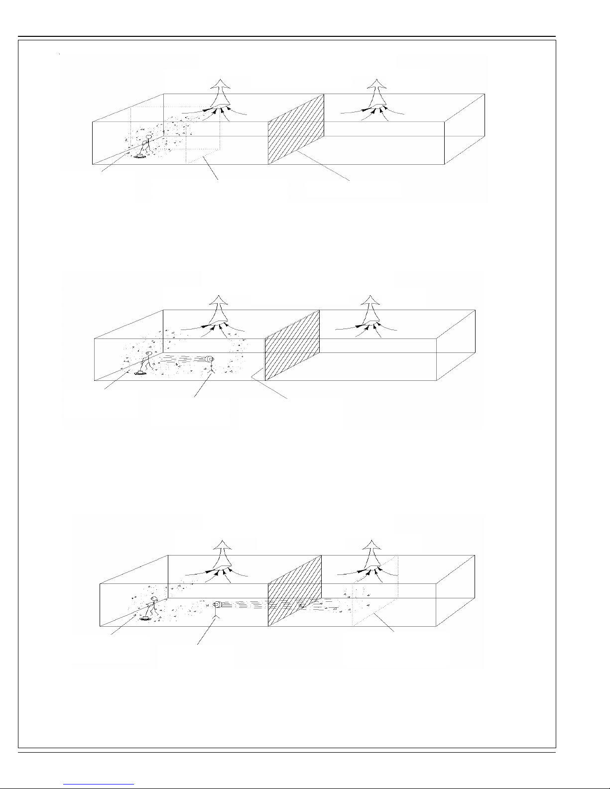
B-6 / ESPAÑOL
MODELO 2
Cambio de aire / Sin mezcla de aire
Flujo de aire Flujo de aire
(Modo rasqueteado)
Le nube de CO
(poco movimiento)
Zona de operación efectiva
(Aumentada hasta ventilación)
Zona divisora
Observe la concentración de CO y la zona de operación efectiva con cambio de aire. La nube de CO sigue concentrada en un área reducida.
Observe la “zona divisora” que se muestra arriba, éste es el lugar donde el fl ujo de aire cambia de dirección. En el Modelo 2, los cambios de aire
se reducen a la mitad ya que prácticamente nada de CO cruza la zona divisora para ser extraído.
MODELO 3
Cambio de aire / Bueno mezcla de aire
Flujo de aire
Le nube de CO
(buen movimiento)
Ventilador
(mezcla de air forzada)
Observe la concentración de CO y la zona de operación efectiva (ampliada hasta la zona divisora) con cambio de aire y mezcla de aire forzada.
La nube de CO sigue concentrada de un lado de la zona divisora. Observe la “zona divisora” que se muestra arriba, éste es el lugar donde el fl ujo
de aire cambia de dirección. En el Modelo 3, los cambios de aire se reducen a la mitad ya que prácticamente nada de CO cruza la zona divisora
para ser extraído.
(Modo rasqueteado)
Zona de operación efectiva
(aumentada hasta zona divisora)
Flujo de aire
MODELO 4
Le nube de CO
(óptima movimiento)
Cambio de aire / Óptima mezclar de air
Flujo de aire
Ventilador
(mezcla de air forzada)
(Modo rasqueteado)
Flujo de aire
Zona de operación efectiva
(aumentada hasta próxima ventilación)
Observe la concentración de CO y la zona de operación efectiva (ampliada pasando la zona divisora hasta la segunda ventilación) con cambio de
aire y mezcla de aire forzada pasando la zona divisora. La nube de CO
se diluye con el aire disponible en el edifi cio. Observe la “zona divisora” que se muestra arriba, éste es el lugar donde el fl ujo de aire cambia de
dirección. En el Modelo 4, los cambios de aire son totales ya que la mezcla de aire forzada se ha movido y mezclado el CO entre todas las zonas
de aire.
B-6 - FORM NO. 56091023 - PBU Propane Burnisher with Dust Control
 Loading...