


Propane Floor Burnisher
with Dust Control
Operator's Manual
Manuel d'utilisation
Libro de Instrucciones
U.S. Patent No. 7,162,771
READ THIS BOOK
LEA ESTE MANUAL
LISEZ CE MANUEL
This book has important information for the use and safe operation of this machine. Failure to read this
book prior to operating or attempting any service or maintenance procedure to your machine could result
in injury to you or to other personnel; damage to the machine or to other property could occur as well.
You must have training in the operation of this machine before using it. If your operator(s) cannot read
this manual, have it explained fully before attempting to operate this machine.
All directions given in this book are as seen from the operator’s position at the rear of the machine.
PBU Models: 08992B (2117BCATCL), 08993B (2717BCATCL)
EN
ES
FR
English (2 - 17)
Español (18 - 33)
Français (34 - 49)
Form No. 71504A 7/08 revised 1/10 Printed in the U.S.A.

ENGLISH
Engine Emissions & CO Safety ........................................................................... 2
Specification Table .............................................................................................10
Operator Safety Instructions .............................................................................. 11
Introduction ........................................................................................................12
Propane Safety Information................................................................................ 13
How to Operate the Machine .............................................................................14
Maintenance and Adjustments ...........................................................................15
Carb Gard Operation .........................................................................................16
Trouble Shooting ................................................................................................ 17
SECTION II - Parts Manual
21" Final Assembly ............................................................................................52
27" Final Assembly ............................................................................................53
Carrier Assembly and Parts List ........................................................................ 54
Handle Assembly and Parts List ........................................................................55
Control Box Assembly and Parts List ................................................................56
Dust Containment Assembly and Parts List ......................................................57
Drive/Wheel/Casting Assembly ......................................................................... 58
Parts List ..................................................................................................59
21" Driver Assembly and Parts List ...................................................................60
27" Driver Assembly and Parts List ...................................................................61
Fuel Assembly and Parts List ............................................................................62
Engine Assembly and Parts List ........................................................................ 63
Engine Assembly and Parts List (Kawasaki FH 381 V "V" Twin) ......................64
Electrical Schematic ..........................................................................................66
EN
Table of Contents
DANGER: It is the owner/operator's responsibility to ensure that the air-exchange system
installed in any location where a propane floor care machine is being operated is of sufficient capacity and quality to support the use of such a machine. OSHA and other County,
State, or Federal Agencies publish guidelines on this subject that are usually most readily
found in the possession of the respective owners and/or parent companies of any location
or chain of locations. Failure on the part of the owner/operator to ensure that a propane
floor care machine can be operated safely in a given location may lead to injury, sickness
or even loss of life.
This Owner's Manual/Safety Procedures Guide has been prepared for the promotion of educational purposes only and
does not claim or assume any responsibility for the operator's actions or safety. To be completely aware of what local
authorities may require, contact the Fire Marshal of your community.
Page -2-
PBU
Operator's Manual (EN) - DC Propane Burnisher

ENGLISH
Engine Emissions and CO Safety
The purpose of this document is to provide information on:
· The potential effects of CO exposure;
· The methods to reduce the risk of CO poisoning;
· The methods used to determine the amount of potential exposure to CO produced by equipment.
DANGER: All LPG (Liquid Propane Gas) powered engines, including this engine, produce Carbon Monoxide
(CO). It is a LETHAL POISON that is a colorless, odorless, tasteless, and non-irritating gas. It is produced by
incomplete combustion of carbonaceous material such as propane (LPG).
Failure to provide for proper venting of CO produced during the operation of combustion powered engines may
result in SERIOUS INJURY OR DEATH to the operator and those in the contaminated area.
EN
The effects of CO can be experienced at different exposure levels, depending on the health of the individual.
Conditions that affect the tolerance of the individual are smoking, age, temperature, humidity, and other
conditions.
WARNING: Read and understand The Operators Manual completely before using this machine
This document explains how CO produced can be managed to reduce the risk of carbon monoxide poisoning.
All distributors, owners, and operators should be aware of the potential effects of CO and the methods used to
prevent over exposure.
We are dedicated to our customers, their safety, and providing information, services, and products that meet
those needs.
Information provided in this document is current as of the date written November 1997.
PBU
Operator's Manual (EN) - DC Propane Burnisher - 3 -

ENGLISH
EN
Document Overview
The information provided in the following overview has been condensed to provide the
reader with a summary of the material presented.
Potential Effects of CO Exposure
• Work place/industry guidelines for CO exposure limits vary substantially from region to region
(OSHA) Permissible Exposure Limit (PEL) for CO is 50 ppm, as an 8-hour time weighted average.
• Definition of CO effects - The toxic effects of carbon monoxide in the blood are the result of tissue
hypoxia (lack of oxygen). The severity depends on the state of activity of the individual and his tissue
oxygen needs.
Methods to Reduce The Risks of CO Poisoning
• Air Exchange and CO Diffusion - CO does not mix with air on its own. Air currents can “stir” the CO
and dilute the concentration values by mixing it with the available air. When using equipment over a large
area in a short time “stirring” occurs as you walk.
• Application Considerations (Burnishing versus Stripping) - When activity is concentrated to a smaller
area as in a stripping application, air “stirring” must be forced by the use of fans to reduce the risk of
high concentrations of CO.
• Air Quality Monitoring – Deployment of a monitor/detector is essential for the safe operation of any
equipment that has the potential to produce CO.
• Room Size and Time Estimations - The concentration and volume of CO production, the size of the
area and the amount of air exchange are factors involved with determining safe time limits for operation
in a specific room size.
• Maintenance of Equipment - LPG engines are dependent on engine tune up, and air filter replacement.
CO concentration (production) skyrockets when the air to fuel ratio becomes fuel rich. Follow the
recommended Maintenance Schedule for the engine.
• Safety Equipment Available. - Envirogard automated fuel to air ratio monitoring and regulation
providing an optimum combustion, three-way type catalytic converter to scrub CO, Hydro Carbons (HC),
and Nitrous Oxide (NOx) from the engine exhaust providing the lowest possible emissions, high cubic feet
per minute (CFM) fans (forced air mixing), and digital combustion analyzers for tail pipe emissions
monitoring.
Page -4-
PBU
Operator's Manual (EN) - DC Propane Burnisher

ENGLISH
EN
Engine Emissions and CO Safety
Potential Effects of CO Exposure
· Work place/industry guidelines for CO exposure limits
· Definition of CO effects
Work place/industry guidelines for CO exposure limits
Limits for permissible exposure to CO vary substantially from region to region. City, State, and Industry require-
ments should be consulted prior to use of any equipment.
The current Occupational Safety and Health Administration (OSHA) Permissible Exposure Limit (PEL) for CO is 50
ppm, as an 8-hour time weighted average (TWA). This is computed by making measurements at intervals over 8 hours,
then adding the sums of the concentrations and the intervals, and dividing by 8 hours. For example:
Time Interval PPM
8:00-9:00 1 HR 100
9:00-10:00 1 HR 25
10:00-11:00 1 HR 25
11:00-12:00 1 HR 50
12:00-1:00 1 HR 50 400ppm/8HR=50ppm TWA
1:00-2:00 1 HR 50
2:00-3:00 1 HR 50
3:00-4:00 1 HR 50
Time intervals = 8 HR ppm = 400
The current National Institute for Occupational Health and Safety (NIOSH), immediately dangerous to life and
health concentration (IDLH) recommended level for CO is 1,200 ppm. NIOSH defines the IDLH exposure level as the
concentration that could result in irreversible health effects or death, or prevent escape from the contaminated environment within 30 minutes.
Definition of CO effects
The toxic effects of carbon monoxide in the blood are the result of tissue hypoxia (lack of oxygen). carbon monoxide
combines with hemoglobin to form carboxyhemoglobin. Since CO and oxygen react with the same group in the hemoglobin molecule, carboxyhemoglobin is incapable of carrying Oxygen. The affinity of hemoglobin for CO is 200 to 240 times
greater than for oxygen. The extent of saturation of hemoglobin with CO depends on the concentration of the gas, the
quantity of inspired air and on the time of exposure. The severity depends on the state of activity of the individual and
his tissue oxygen needs.
According to Harrison’s Principles of Internal Medicine 7th edition, no symptoms will develop at a concentration of
0.01% CO (100ppm) in inspired air, since this will not raise blood saturation above 10 %. Exposure to 0.05% (500ppm) for
1 hour during light activity will produce a blood concentration of 20% carboxyhemoglobin and result in a mild or
throbbing headache. Greater activity or longer exposure causes a blood saturation of 30 to 50 %. At this point head
ache, irritability, confusion, dizziness, visual disturbance, nausea, vomiting, and fainting can be experienced. Exposure
for one hour to concentrations of 0.1% (1000ppm) in inspired air the blood will contain 50 to 80% carboxyhemoglobin
which results in coma, convulsions, respiratory failure and death. On inhalation of high concentrations of CO, saturation
of the blood proceeds so rapidly that unconsciousness may occur suddenly without warning.
PBU
Operator's Manual (EN) - DC Propane Burnisher - 5 -
ENGLISH
EN
Methods to Reduce The Risks of CO Poisoning
• Air Exchange and CO Diffusion
• Application Considerations (Burnishing versus Stripping)
• Air Quality Monitoring
• Room Size and Time Estimations
• Maintenance of Equipment
• Safety Equipment Available
Air Exchange and CO Diffusion
The most reliable method to prevent CO Poisoning is to ensure all the CO produced is vented outside. With wood
stoves or gas heaters this is performed with ductwork that carries the exhaust and CO outside. Non-stationary
combustion type equipment must be used in such a way that CO is not allowed to rise to a harmful or dangerous level.
CO does not readily dissipate or mix with air on its own. Air currents can “stir” the CO and dilute the concentration
or ppm values by mixing it with the available air. When using equipment over a large area in a short time “stirring”
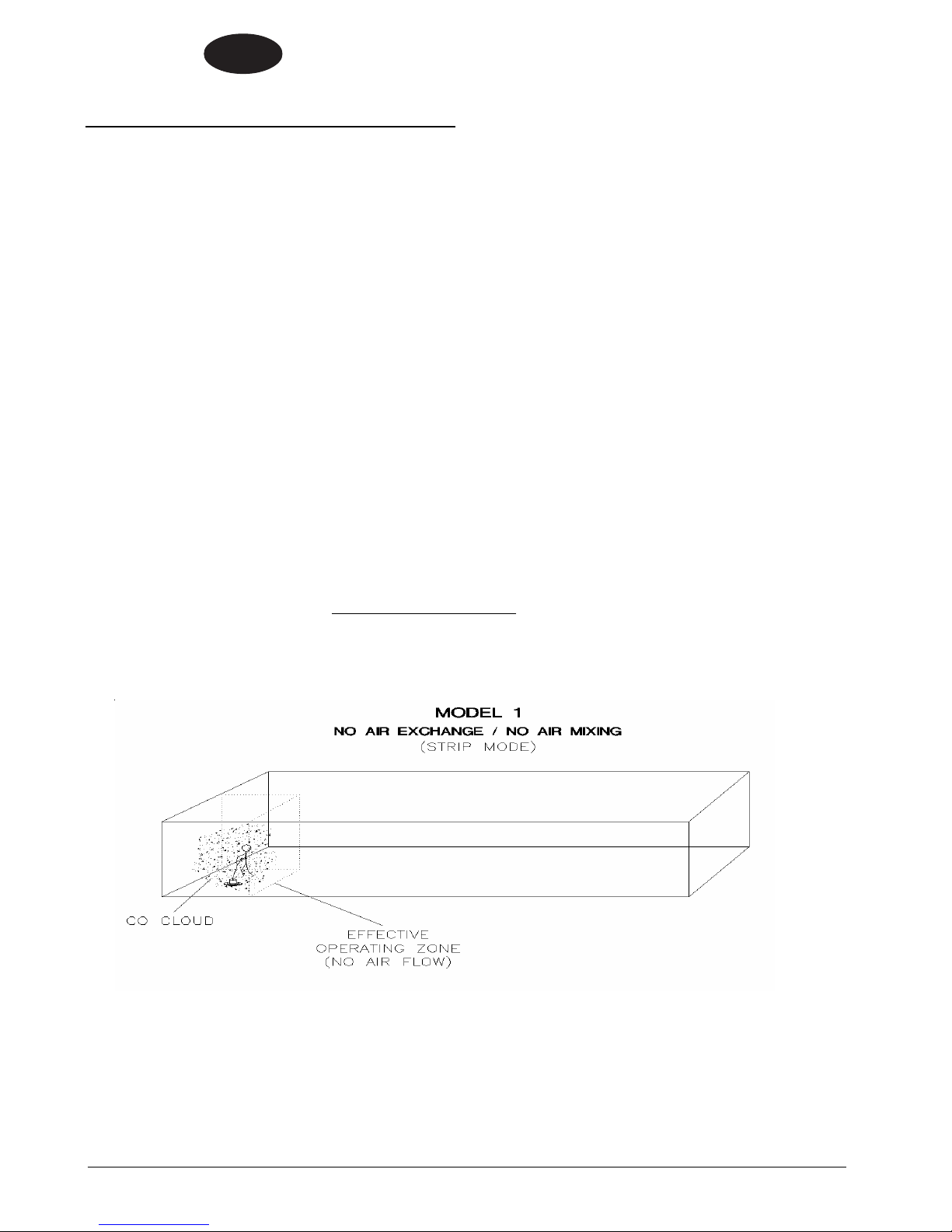
occurs as you walk, or to say it another way, your Effective Operating Zone is large. When activity is concentrated to a
smaller area as in a stripping application, the Effective Operating Zone is small, and “stirring” must be forced by the use
of fans to increase the Effective Operating Zone and reduce high concentrations of CO.
Air exchange rates (air exchange is defined as the exhausting of internal air to the external atmosphere), the size of
the Effective Operating Zone, amount of CO produced, level of human activity, and the duration of exposure are all
factors in the determination of the production of carboxyhemoglobin and the amount of CO blood saturation.
Application considerations (Burnishing versus Stripping)
When using equipment over a large area in a short time, as in most burnishing applications, your Effective
Operating Zone is large. When activity is concentrated to a smaller area as in stripping applications, the Effective
Operating Zone is small and stirring or CO mixing MUST be forced by the use of fans to increase the Effective
Operating Zone and reduce high concentrations of CO.
Caution: air mixing in itself may not be sufficient to reduce CO to a safe level.
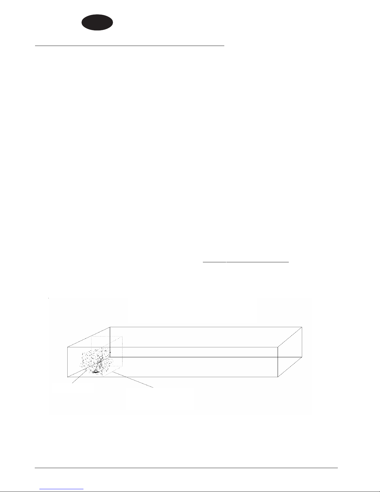
The Effective Operating Zone can be defined as the area covered in a given time.
Stripping is quite a different type of operation than burnishing, and carries with it substantially more hazards, as
stripping is a low movement operation compared to burnishing (less floor space for the same time). As shown in Model
1, the CO concentrations rise much quicker as the “Effective Operating Zone” is a very small area compared to the total
building size.
Page -6-
PBU
Operator's Manual (EN) - DC Propane Burnisher
ENGLISH
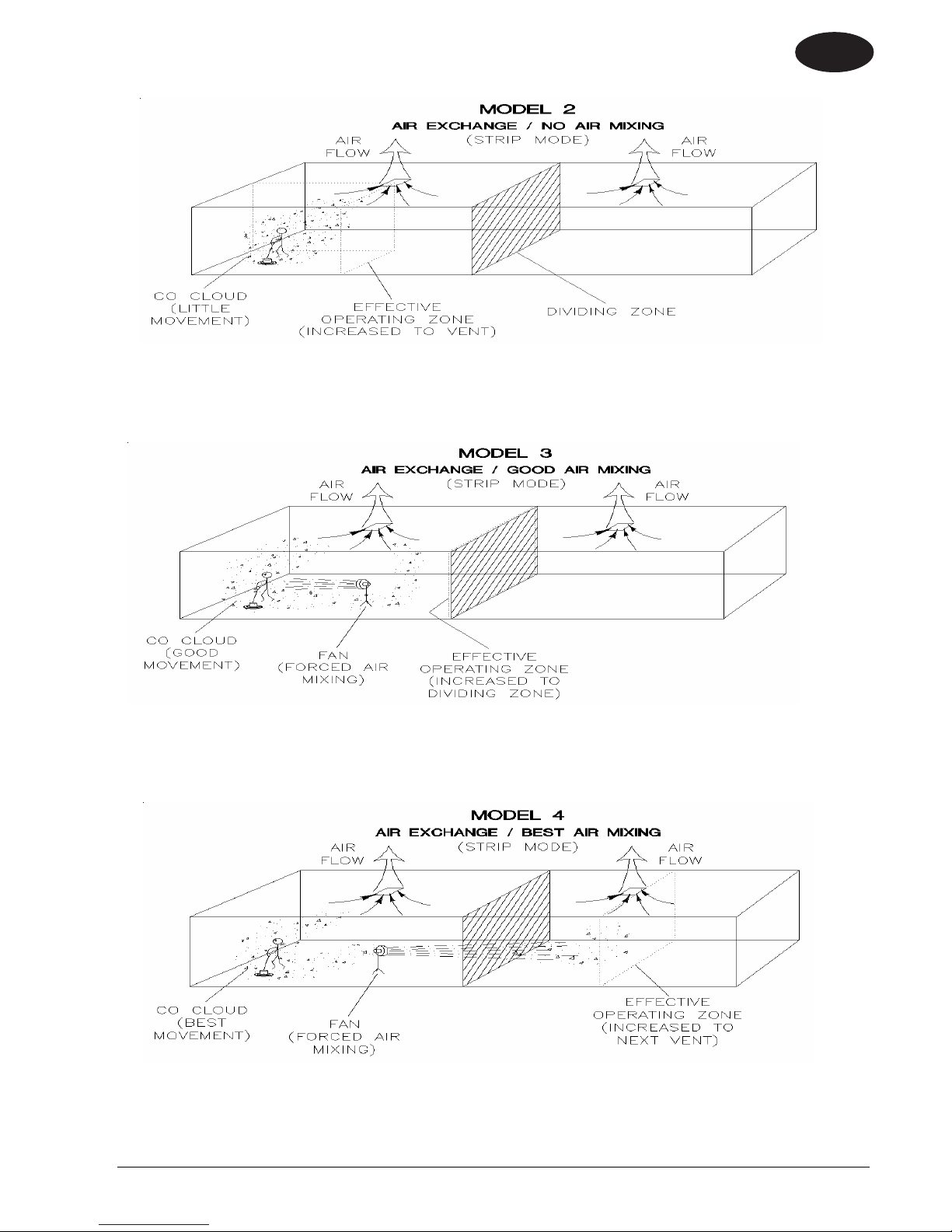
Notice the CO concentration and the Effective Operating Zone with air exchange. The CO cloud is still concentrated
in a small area. Note the “Dividing Zone” shown above, this is the line where airflow changes direction. In Model 2, air
changes are cut in ½ as little or no CO crosses the Dividing Zone to be exhausted.
EN
Notice the CO concentration and the Effective Operating Zone (Expanded to the Dividing zone) with air exchange and forced air mixing. The CO cloud is still concentrated on one side of the Dividing zone. Note the
“Dividing Zone” shown above, this is the line where airflow changes direction. In Model 3, air changes are cut in
½ as little or no CO crosses the Dividing Zone to be exhausted.
Notice the CO concentration and the Effective Operating Zone (Expanded through the Dividing zone to the second
vent) with air exchange and forced air mixing through the dividing Zone. The CO cloud is diluted with the available air in
the building. Note the “Dividing Zone” shown above, this is the line where airflow changes direction. In Model 4, air
changes are full as forced air mixing has moved and mixed the CO between all air zones.
PBU
Operator's Manual (EN) - DC Propane Burnisher - 7 -
ENGLISH
EN
Air Quality Monitoring
Warning: Deployment of a monitor/detector is essential for the safe operation of any equipment that has the
potential to produce CO. CO sensors/detectors became available on the mass market around 1978. At present several
brands sell in the fifty-dollar range. The main differences between the technologies involved are battery or electric and
Semiconductor or Biomimetic types. Detectors for carbon monoxide (CO) are manufactured and marketed for use in
either the home or occupational industrial settings. The detectors for home use are devices that will sound an alarm
before CO concentrations in the home become hazardous. There is an Underwriters Laboratories, Inc., performance
standard (UL 2034) for residential CO detectors. Detectors currently available on the market are battery-powered, plugin, or hard-wired. Some models incorporate a visual display of the parts per million (ppm) concentration of CO present in
the home. For more information on CO detectors for home use, call the Consumer Product Safety Commission Hotline at
1-800-638-2772.
CO detectors for use in residential settings are not designed for use in typical workplace settings. Monitoring
requirements in an occupational setting are different from monitoring requirements in the home. In the workplace, it is
frequently necessary to monitor a worker’s exposure to carbon monoxide over an entire work shift and determine the
time-weighted average (TWA) concentration of the exposure. It may also be necessary to have carbon monoxide
monitors with alarm capabilities in the workplace. The direct-reading instruments are frequently equipped with audio
and/or visual alarms and may be used for area and/or personal exposure monitoring. Some have microprocessors and
memory for storing CO concentration readings taken during the day. It is significant to note that some of the devices
mentioned for workplace CO monitoring are not capable of monitoring TWAs, and not all are equipped with alarms. The
appropriate monitor must be chosen on an application-by-application basis. For more information on the availability of
workplace CO monitors or their application, call the National Institute for Occupational Safety and Health at 1-800-35NIOSH (1-800-356-4674).
Room Size and Time Estimations for Parts Per Million (PPM) CO
The fundamental factors in area CO levels involve:
The concentration and volume of CO production;
The size of the area;
The amount of *air exchange if any;
The amount of time CO is produced.
Multiplying length, width, and height will determine the volume or cubic feet in a room. So an empty building 100ft
by 100ft with a 10ft ceiling would be 100,000 cubic ft. in size. Any material that is in the room and takes space would
reduce the cubic feet.
*Air exchange is defined as the exhausting of internal air to the external atmosphere.
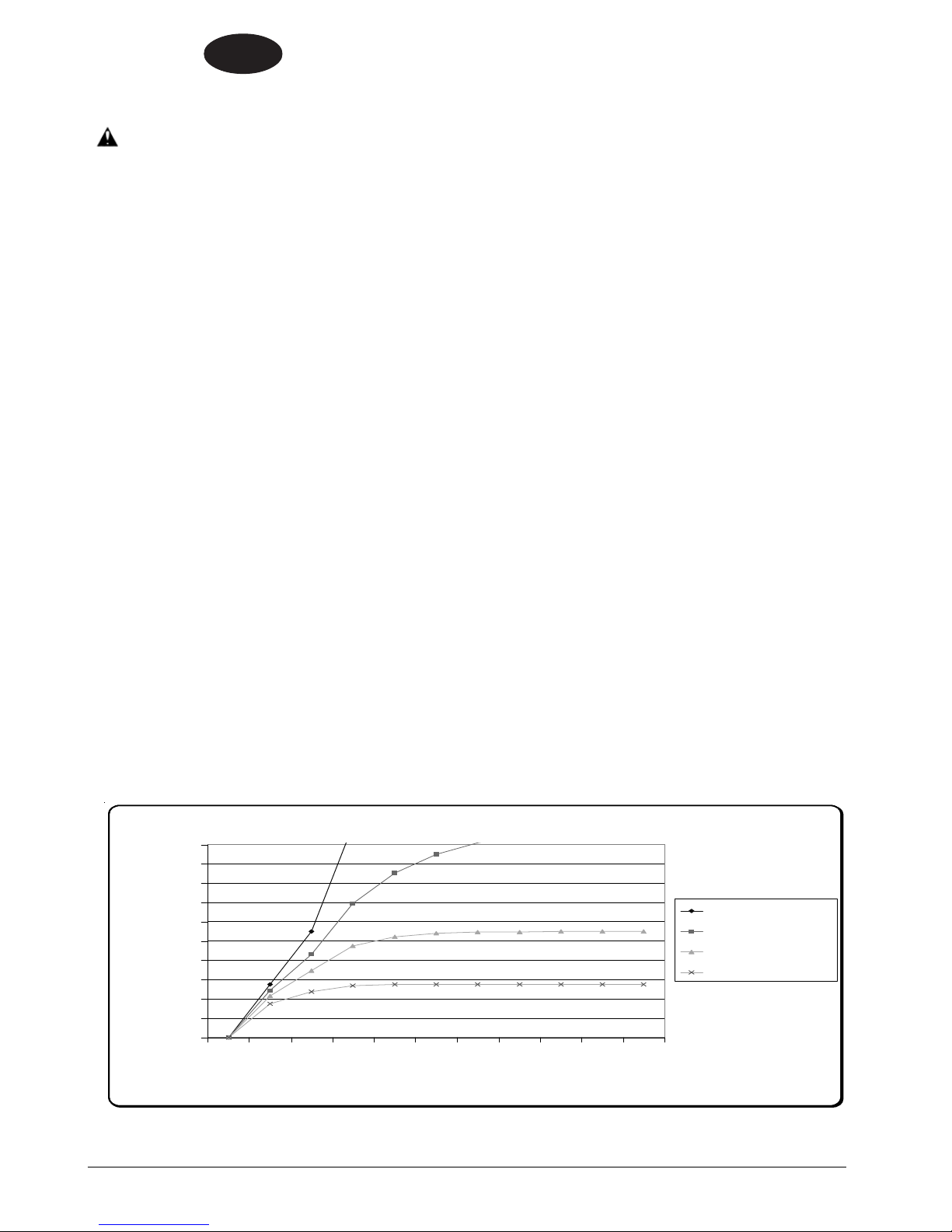
The Graph above depicts the relationships of air exchange to time and CO ppm with cubic feet area and percent CO
emissions remaining constant.
1.5% CO Em ission in 100,000 cubic feet with 480cc 14 HP Engine and complete air/CO mixing
500
450
400
350
300
250
PPM
200
150
100
50
0
0.5123456789
Time (hours)
0.0 change/hr
1/2 change/hr
1 changes/hr
2 changes/hr
Page -8-
PBU
Operator's Manual (EN) - DC Propane Burnisher
ENGLISH
8 Hour Time Weighted Average (OSHA Method)
1.5 %CO 100,000cf Hours Operation 1 2 3 4 5 6 7 8
TWA (OSHA Method) 0 change/hr 34 103 206 343 514 719 959 1232
1/2 change/hr 27 70 124 183 246 311 378 445
1 change/hr 22 51 84 118 152 186 220 255
2 change/hr 15 32 49 66 83 100 117 135
Based on the CO production rates shown above the TWA would be exceeded in a 100 x 100 x 10 foot (empty) space
after 3 hours with 2 air changes per hour. (Assumes no additional CO exposure during 8 hour time period)
EN
PPM
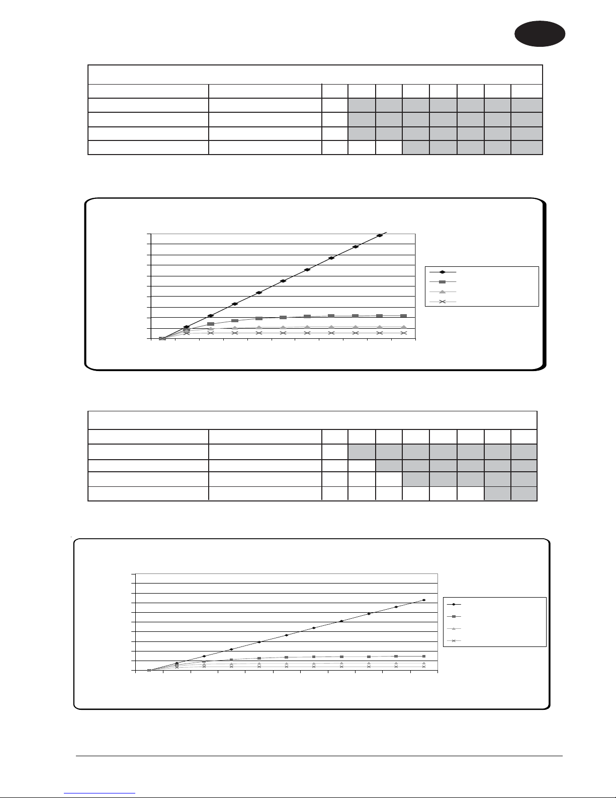
1.5% C O Em issio n in 500,000 cu b ic fe et w ith 480cc 14 H P
500
450
400
350
300
250
200
150
100
50
0
012345678910
Engine and com plete air/CO m ix ing
0.0 change/hr
1/2 change/hr
1 changes/hr
2 changes/hr
Tim e (hours)
The Graph above depicts the relationships of air exchange to time and CO ppm with cubic feet area
and percent CO emissions remaining constant.
8 Hour Time Weighted Average (OSHA Method)
1.5 %CO 500,000cf Hours Operation 1 2 3 4 5 6 7 8
TWA (OSHA Method) 0 change/hr 17 51 103 171 257 360 479 612
1/2 change/hr 14 35 62 92 123 156 189 223
1 change/hr 11 26 42 59 76 93 110 127
2 change/hr 7 16 24 33 42 50 59 67
Based on the CO production rates shown above the TWA would be exceeded in a 100 x 500 x 10 foot (empty) space
after 6 hours with 2 air changes per hour. (Assumes no additional CO exposure during 8 hour time period)
1.5% CO Em ission in 750,000 cubic feet with 480cc 14 HP Eng ine and com plete air/C O mixing
500
450
400
350
300
250
PPM
200
150
100
50
0
012345678910
The Graph above depicts the relationships of air exchange to time and CO ppm with cubic feet area and percent CO
emissions remaining constant.
PBU
Operator's Manual (EN) - DC Propane Burnisher - 9 -
0.0 change/hr
1/2 change/hr
1 changes/hr
2 changes/hr
Tim e (hours)

ENGLISH
EN
8 Hour Time Weighted Average (OSHA Method)
1.5 % 750,000cf Hours Operation 1 2 3 4 5 6 7 8
TWA (OSHA Method) 0 change/hr 5 14 27 46 69 96 128 164
1/2 change/hr 4 9 16 24 33 42 50 59
1 change/hr 3 7 11 16 20 25 29 34
2 change/hr 2 4 7 9 11 13 16 18
Based on the CO production rates shown above the TWA would not be exceeded in a
100 x 750 x 10 foot (empty) space after 8 hours with 2 air changes per hour. (Assumes no additional CO
exposure during 8 hour time period)
Maintenance of Equipment
Warning: The proper maintenance of equipment is vital to safe operation. LPG engines are dependent on
engine tune up, and air filter replacement. CO concentration (production) skyrockets when the air to fuel ratio becomes
fuel rich. Follow the recommended Maintenance Schedule for the engine found in the Engine Operator/Owner Manual as
well as the Maintenance And Adjustments schedule found in the Propane Floor Equipment Operator’s Manual that were
supplied with the equipment. Additional manuals may be obtained by contacting at 1-800-545-3454 or write to Customer
Service, 2100 Hwy. 265, Springdale AR 72764.
CO Safety Equipment Available
• Envirogard automated fuel to air ratio monitoring and regulation providing an optimum combustion
• Three-way type catalytic converter to scrub CO, Hydro Carbons (HC), and Nitrous Oxide (NOx) from the engine
exhaust providing the lowest possible emissions
• High cubic feet per minute (CFM) fans (forced air mixing)
• Digital combustion analyzers for tail pipe emissions monitoring
SPECIFICATIONS:
Model Dust Control
2117BCATCL 2717BCATCL
Part Number 08992B 08993B
Pad Size 21" (53 cm) 27" (68 cm)
Engine 17 hp Twin-V Kawasaki
Catalytic Muffler Yes
Carb Gard Yes
Clutch Centrifugal
Pad Speed 2100 RPM 1500 RPM
Propane Tank 20 lb. (9.1 kg) Capacity, 80% Safety fill
Auto Fuel Shutoff Yes
Low Oil Shutdown Yes
Hour Meter Yes
Sound Level 87 - 89 dB(A)
Productivity Rate 25,000 ft2/hr (2,322 m2/hr) 33,000 ft2/hr (3,066 m2/hr)
Agency Approvals EPA plus UL Approved Propane Components
CARB Certified
(California Air Resource Board)
Weight 276 lbs. 298 lbs.
Dimensions:
Length 66" (167.4 cm) 69" (175.3 cm)
Widith 23.5" (59.7 cm) 29.5" (74.9 cm)
Height 43" (109.2 cm) 43" (109.2 cm)
Warranty 2 Year Parts & Labor
Yes
Page -10-
PBU
Operator's Manual (EN) - DC Propane Burnisher
ENGLISH
EN
OPERATOR SAFETY INSTRUCTIONS
DANGER means: Severe bodily injury or death can occur to you or other personnel if the DAN-
GER statements found on this machine or in this Owner's Manual are ignored
or are not adhered to. Read and observe all DANGER statements found in
this Owner's Manual and on your machine.
WARNING means: Injury can occur to you or to other personnel if the WARNING statements
found on your machine or in this Owner's Manual are ignored or are not
adhered to. Read and observe all WARNING statements found in this Owner's
Manual and on your machine.
CAUTION means: Damage can occur to the machine or to other property if the CAUTION
statements found on your machine or in this Owner's Manual are ignored or are
not adhered to. Read and observe all CAUTION statements found in this
Owner's Manual and on your machine.
DANGER: Failure to read the Owner's Manual prior to operating or attempting any service or mainte-
nance procedure to your machine could result in injury to you or to other personnel;
damage to the machine or to other property could occur as well. You must have training in
the operation of this machine before using it. If you or your operator(s) cannot read
English, have this manual explained fully before attempting to operate this machine.
DANGER: Moving parts of this machine can cause serious injury and/or damage. Do not allow contact
of clothing, hair, hands, feet, or other body parts with the rotating pad. Keep other people away
from the machine while it's in operation.
DANGER: Injury to the operator or bystanders could occur if the machine's power is on while changing
the buffing pad or making machine adjustments. Never try to change the buffing pad or attempt
to make machine adjustments while the engine is running.
DANGER: Cigarette lighters, pilot lights and any other source of ignition can create an explosion if it comes
in contact with propane. Propane is a highly flammable fuel. All sources of ignition should be
extinguished or removed entirely if possible from the work area. DO NOT SMOKE in the vicinity
of propane powered floor equipment.
DANGER: This machine emits carbon monoxide. Asphyxiation could occur if the unit is used in an area
with poor or inadequate ventilation. Operate machine in a well ventilated area only. If a
headache develops, shut off the machine. Have it checked for carbon monoxide emissions
by a qualified shop before using it again.
DANGER: Dangerous carbon monoxide emissions from this machine are greatly increased due to a dirty
combustion air cleaner. Follow the engine manufacturer's air cleaner service instructions.
DANGER: Propane is highly flammable. If you smell propane gas, shut off the machine and move it
outside. Determine and repair the source of the leak before restarting. NEVER vent propane
gas inside a building. Disconnect the fuel line from the tank, remove the tank from the machine
and then store the propane tank in a secrue storage cabinet outside the building. It is
UNLAWFUL to store a propane bottle inside a building.
WARNING: Long or continuous exposure to high noise levels may cause permanent hearing loss.
Always wear hearing protection while using this machine.
WARNING: Injury to the eyes and/or body can occur if protective clothing and/or equipment is not worn
while using this machine. Always wear safety goggles and safety clothing while using this
machine.
PBU
Operator's Manual (EN) - DC Propane Burnisher - 11 -

ENGLISH
EN
WARNING: Severe burn or injury could occur if you touch the hot muffler or exhaust pipe. Do not touch
the hot muffler or exhaust pipe.
WARNING: To avoid injury or damage to the machine, do not tip the machine fully upward while the engine
is running.
WARNING: Any alterations or modifications of this machine could result in damage to the machine or injury
to the operator or other bystanders. Alterations or modifications not authorized by the
manufacturer voids any and all warranties and liabilities.
WARNING: To avoid injury or property damage, do not leave the machine where it can be tampered with
or started by persons untrained in its operation. You must have training in the operation of
this machine before using it. DO NOT leave the machine running unattended.
WARNING: Substantial damage to the floor, the machine, or personnel may result if the machine is
operated with the pad off center, damaged or missing. Do not operate the machine if the pad
is off center, damaged or missing.
WARNING: Operating a machine that has loose parts could result in injury or property damage. Do not
operate this machine if there are loose parts. Inspect the machine for loose parts frequently.
This will promote safe operation and a long life for the machine.
WARNING: Vibration from machinery may cause numbness or tingling of the fingers in certain people.
Smoking, dampness, diet, and heredity may contribute to the symptoms. Wearing warm
clothing, gloves, exercising and refraining from smoking can reduce the effects of vibration.
If the symptoms still persist, discontinue operation of the machine.
Introduction
This propane floor care equipment is manufactured in
two basic concepts: the buffer/burnisher and the floor
stripper. Both of these designs are truly PORTABLE
equipment. Propane buffers are best defined as ultra
high speed buffers with the staying power to produce
superior high gloss floor surfaces. Upon contact with the
floor, the buffer should always be kept moving. The
speed at which you walk will determine the results that
you will obtain. Slower speeds create more heat and
therefore more shine. A moderate pace is recommended for best results and safe operation. NEVER
RUN WITH THE BUFFER!! While a credible shine will
still result, the danger of trying to stop the machine in an
emergency situation is unacceptable. When buffing,
avoid loose tile, electric outlets, door thresholds and any
object which may come in contact with the pad other than
the floor itself. REMEMBER, the pad is turning very
rapidly.
Proper care and maintenance will protect your investment and keep your machine serving you for many years
to come. It is essential that these issues are closely
followed:
CAUTION: Overfilling the propane tank is the
number one cause of problems with a
propane machine. This can cause
the engine to run poorly or not at all.
In addition, overfilling allows liquid propane to
enter the fuel control system, possibly ruining
the lockoff/regulator assembly. This voids the
warranty on affected parts of the machine. To
avoid problems, read and understand fully, the
section "Filling and Storing Propane Tanks."
OVERHEATING
Keep the cooling air bonnet filter clean. Protect your
machine; don't allow wax dust/lint to build up on the
cooling fins of the engine cylinder(s). A good high
pressure spray wash directed at the fins
engine
is cold will prevent this from happening.
LOW OIL AND DIRTY OIL
other failures. recommends changing the oil
regular schedule
found in the engine manufacturers' manual. Checking the oil daily, before putting the machine to work, is
a good habit to get into and could save you the
downtime and expense of replacing the engine due
to oil starvation. AFTER AN OIL CHANGE, MAKE
SURE YOU HAVE REPLACED THE OIL SUPPLY
BEFORE RESTARTING THE ENGINE.
is a major cause of engine failure.
when the
account for most of the
on a
, perhaps exceeding that which is
Page -12-
PBU
Operator's Manual (EN) - DC Propane Burnisher

Propane Safety Information
ENGLISH
EN
Facts About LP Gas - Propane
As a fuel, Propane gas is unmatched for both safety and
dependability. It has been used as a domestic household
fuel for over half a century, and for over thirty years as an
internal combustion engine fuel. Propane is a highly
flammable fuel that is contained under pressure as a
liquid. Vaporized gas has a similar explosive force to
gasoline and mixtures as low as 2% LP Gas to air may be
ignited in a closed environment. Care should be
exercised to avoid escaping vapor as it can freeze skin
and cause frost bite. Vaporized fuel is heavier than air and
will collect in the lowest confined space available.
Facts About Propane Tanks
Propane tanks are constructed according to ASME or
Federal DOT #4ET20 pressure safety codes. Including the
tank, all valves and fittings are UL Listed. Propane gas is
noncorrosive and will not rust the inside of a tank. Should
the tank exterior become damaged or rusted, discontinue
DO NOT
use.
valves.
propane buffer.
with a barbecue grill, etc. recommends having propane
tanks tested once a year by an authorized National LP Gas
Association sanctioned propane dealer.
The fuel tank is supplied directly from the manufacturer
and is void of fuel. This tank must be purged at the time of
the first fill. Local fuel vendors should be familiar with this
operation and will provide this service.
tamper with tank gauges or safety relief
NEVER
use a tank not intended for use with a
DO NOT
substitute tanks that are used
Recommended Purge Procedures
How to purge new LP-Gas Buffer cylinders equipped with
the Overfill Prevention Device:
New containers may contain vapor, air, or other
contaminants. It is essential that these be removed before
filling the container and placing it into service. Air in the
container will cause abnormally high pressure, with the
result that the pressure relief valve may open.
system is also likely to cause lean mixture, making
ignition difficult.
depressurized or open to the atmosphere for a period of
time, it must be re-purged as if it were a new container.
If a cylinder is suspected of being
Air in the
3. Make the connection to the quick coupler (A purge manifold
system is most effective). Fully open the cylinder service
valve as well as the outage valve. Vent to a safe atmosphere. A vent stack is recommended.
4. On Overfill Prevention Device cylinders, the purge time is
increased as a result of the new valve design. Opening the
outage valve will help improve the speed of the purge.
5. Repeat #3 and #4 for a total of FIVE purges.
6. Repressurize the container with odorized LP-gas vapor to 15
psig.
7. The container is now ready to be filled with LP-gas.
8. Once filled, check all fittings and tank openings for leaks
using an approved leak detector solution.
9. The container is now ready to be placed in service. Add
DOT and OSHA labels.
Symptoms of a non-purge cylinder:
• Relief valve opens due to over pressurized
cylinder creating hazardous situation.
• Moisture in the cylinder.
• Buffer operates initially but shuts down when
fuel mixture becomes too lean.
Refilling & Storing Propane Tanks
The NFPA Technical Committee prohibits the storage of
such containers in buildings. There are few exceptions to
this rule. In other words, propane tanks should NOT be
stored in buildings used by the public or frequented by
anyone passing through or who is working in the building.
Full or empty, never leave tanks in small enclosed areas.
The tank(s) must be in a secure, tamper-proof storage
enclosure that provides safety from accident or vandalism.
A propane tank can be transported either on or off of the
machine. In either case it should be secured to the
vehicle in its upright position with the service valve closed.
Never leave your tanks in a vehicle unsecured or lying on
their side.
TRANSPORTED, INSTALLED AND USED IN AN
UPRIGHT POSITION.
PROPANE TANKS SHOULD ALWAYS BE
To purge a container, the following steps should be
taken.
Purging of containers should be performed in an approved
area (see NFPA #5 8) using NPGA #13 3.89(a) procedure.
1. Determine if the container pressure is zero. Should the
cylinder contain only pressurized air, the air may be vented
directly to the atmosphere through the service valve using an
adapter and the outage valve.
2. Pressurize the container to approximately 15 psig with LPgas vapor.
will cause the moisture vapor to chill and remain in the
cylinder. LPgas liquid also expands 270 times to
vapor making the purge process ineffective.
Never purge with liquid LP-gas!
gas vapor only!
PBU
Operator's Manual (EN) - DC Propane Burnisher - 13 -
To do so
Use LP-
OVERFILLING PROPANE TANKS IS HAZARDOUS.
The tank should NEVER be completely filled with liquid
propane. 80% of the total tank volume is to be considered
at
ALL
times as full. EXPANSION MUST BE ALLOWED
FOR. Propane Buffer tanks are equipped with a fixed
liquid level gauge which contacts the liquid level at 80% of
container capacity, allowing 20% for expansion. The top
part of this device must be unscrewed counterclockwise
so that vapor can escape through the small hole it its side,
as the tank is refilled. When the escaping vapor starts to
give way to liquid, the device must be quickly closed and
the propane nozzle turned off.
**IMPORTANT** The engine and the fuel system on
your floor care machine are designed to run on fuel
vapor, not fuel liquid. Overfilling the propane tank will
result in damaging the lockoff and/or regulator. This will
VOID the WARRANTY on these components.

ENGLISH
EN
How to Operate the Machine
Preparing The Machine For Use
BEFORE using any type of powered equipment, proper
safety dictates you should visually inspect it.
1.
Adjusting the Handle -
(a) Adjust the handle to a comfortable height by
pulling outward on the two spring-loaded pins on
each side of the handle.
(b) While holding the pins out, adjust the handle to
the height desired.
(c) Release the pins so that they insert themselves
into the locked positions. NOTE: It may be easier
to stand to one side of the handle and reach
across to the other side to make the adjustment.
2.
Bonnet Filter
engine is clean. It should be changed hourly and
thoroughly cleaned before reuse.
Oil Level
3.
(a) Check the engine OIL LEVEL.
(b) With the buffer sitting in a level position, unscrew
the yellow oil filler cap, pull out, and wipe dipstick
off with a clean cloth.
(c) Insert the dipstick into the tube, but DO NOT
screw it back in.
(d) Pull the dipstick out and check the oil level
making sure the oil level is in the operating range
(grid area) shown on the dipstick. If the oil level is
in the "ADD" range, add enough engine oil to
bring the oil level to the operating range. NOTE:
NEVER overfill the engine oil as this can lead to
irreparable damage to the engine.
4.
Filling the Tank-
as given under the previous heading: "Refilling And
Storing Propane Tanks." In addition, if your buffer
came with an "80% Safety Fill Tank" then it should
ONLY be filled through the threaded valve with the
larger diameter that is covered by a yellow cap to
ensure a "Full" level that is safe.
5.
Pad and Pad Holder
Inspect the condition of the pad and pad holder.
(a) Adjust handle to it's extreme upright position.
(NOTE: Pins should be in the hole marked
"TILTBACK").
(b) Grabbing the handle with both hands and placing
your foot on the back deck of the burnisher for
stability, pull back on the handle and tilt the
machine back.
(c) Let the handle rest on the floor to hold the
machine in the upright position.
(d) Go to the pad side of the machine for inspection
and/or replacement. Is there a pad? Is it properly
attached? What is it's condition? Ensure the pad
is clean and has at least a thickness of 1/3 of an
inch. Always turn off the engine before checking
the pad.
- Make sure the bonnet air filter atop the
-
Fill the tank following the instructions
-
7.
Dust Containment Area
Check the dust containment area and make sure
that it is clean. This is the area underneath the
propane tank.
(a) Remove the propane tank and then lift the black
lid and locate the automotive-type filter.
(b) Inspect the filter. Is it dirty? Does it need to be
cleaned or replaced? Make sure that the trough that is outside of and below the level of the filter is clean.
Dust Skirt -
8.
surrounds the deck. Is it in good condition? What is
the condition of the rubber boot that connects the skirt
to the rear part of the deck? Replace the boot if it is
ripped or torn.
Starting the Engine
1. Open the service valve on the propane tank by turning
counterclockwise, about one and a half turns.
2. Ensure the buffer is tilted back so that the pad is off the
floor
on all machines without a clutch.
3. The Kawasaki 17 hp twin cylinder is designed to be
started with the throttle in the idle position. This creates
a vacuum necessary to open the lock-off valve inside
the regulator. Actuation of the throttle lever will keep
the lock-off valve from opening and the engine from
getting fuel so the engine will not start. Proper maintenance will insure easy starting.
4. Engage starter for a MAXIMUM of 5 to 6 seconds or
until the engine fires. Serious starter damage will result
if this is exceeded and the warranty may not apply.
5. Operate the engine at half throttle for approximately two
minutes for proper warm-up. Then advance to full
throttle for best results.
NOTE: If the engine refuses to start, see the Trouble
Shooting Guide.
Stopping The Engine
1. Close the service valve on the propane tank, by turning
clockwise. This consumes all of the propane that is still
in the fuel system.
2. ALWAYS allow the engine to run until it stops from lack
of fuel, and then shut off the key switch. ** ONLY IN AN
EMERGENCY should the "kill switch" on buffer be
used.
3. Disconnect the fuel line from the tank.
Check out the condition of the skirt that
-
6.
Tank and Fuel Lines
covered but do the fuel lines show any sign of wear
and tear, such as cracks or any corrosion? Screw the
brass fuel line fitting onto the tank service valve, hand
tight only. This connection MUST be secure because
the service valve has a safety valve inside it which will
only open if the brass fuel line fitting is COMPLETELY
seated into the service valve.
Page -14-
- The tank has already been
4. REMEMBER, when you are finished with the machine,
store the propane tank outside the building, in a safe
place away from heat or direct sunlight.
PBU
Operator's Manual (EN) - DC Propane Burnisher

ENGLISH
EN
Maintenance And Adjustments
Emission Control Information
To protect the environment in which we will live, the
manufacturer has incorporated crankcase emission (1) and
exhaust emission (2) control systems (EM) in compliance
with applicable regulations of the United States Environmental Protection Agency and California Air Resources
Board.
1.
Crankcase Emission Control System -
crankcase emission control system is used to eliminate
blow-by gases. The blow-by gases are led to the
breather chamber through the crankcase. Then, it is led
to the air cleaner. Oil is separated from the gases while
passing through the inside of the breather chamber
from the crankcase, and then returned back to the
bottom of crankcase.
2.
Exhaust Emission Control System -
emission control system applied to this engine consists
of a carburetor and an ignition system having optimum
ignition timing characteristics. The carburetor has been
calibrated to provide lean air/fuel mixture characteristics
and optimum fuel economy with a suitable air cleaner
and exhaust system.
Tampering w/Emission Control System Prohibited
Federal law and California State law prohibits the following
acts or the causing thereof: (1) the removal or rendering
inoperative by any person other than for purposes of
maintenance, repair, or replacement, of any device or
element of design incorporated into any new engine for the
purpose of emission control prior to its sale or delivery to
the ultimate purchaser or while it is in use, or (2) the use of
the engine after such device or element of design has been
removed or rendered inoperative by any person.
Among those acts presumed to constitute tampering are the
acts listed below:
Do not tamper with the original emission related part.
>Carburetor and internal parts
>Spark plugs
>Magneto or electronic ignition system
>Fuel filter element
>Air cleaner elements
>Crankcase
>Cylinder heads
>Breather chamber and internal parts
>Intake pipe and tube
General Maintenance and Adjustments
1.
Fuel Control System -
adjustments should ONLY be made by a qualified LPG
system technician or an authorized service center,
using an exhaust gas analyzer. Do not operate the
machine if carbon monoxide levels exceed OSHA
standards.
2.
Pad Replacement-
(a) Adjust handle to its extreme upright position (Note:
Pins should be in the hole marked "TILTBACK").
(b) Grabbing the handle with both hands and placing
your foot on the back deck of the burnisher for
stability, pull back on the handle and tilt the
machine back.
(c) Let the handle rest on the floor to hold the machine
in the upright position.
To ensure personal safety,
A sealed-type
The exhaust
(d) Now move to the pad side of the machine.
(e) Grab the metal clip, which is located in the
white center-lock device, between the thumb
and index finger and squeeze. This allows the
pad retainer to "pop" off.
(f) Remove the old pad.
(g) Install the new pad by carefully centering it
against the "harpoon hook" plastic gripper.
(h) Replace the pad retainer by snapping it back in
place (Note: The center-lock ring should "snap"
twice).
(i) Check the rotation of the pad driver. Eccentric-
ity of the pad should not exceed 1/4 of an inch.
3.
Belt Replacement -
(a) Tilt the machine back as you would to replace
the pad.
(b) Using a 3/4" open-end wrench, secure the shaft
from the engine side of the deck and spin off the
pad driver to remove it.
(c) Use the same 3/4" wrench to release tension on
the belt by rotating the Lovejoy tensioner
towards the belt.
(d) Release the Lovejoy tensioner and carefully
remove the belt from the engine clutch and the
drive pulley.
(e) Now install the new belt onto the clutch and
pulley and use the wrench to again release the
tension on the Lovejoy tensioner until the belt is
in position.
(f) Release the Lovejoy tensioner to apply tension
to the belt. (Note: the arrow on the Lovejoy
tensioner should be pointing towards 30°. If it is
not, reset the tensioner by first loosening and
then re-tightening the bolt that holds the
tensioner to the deck).
(g) Reinstall the pad driver.
Changing the Engine Oil -
4.
(a) Start and warm up the engine so the oil will
drain easily.
(b) Stop the engine.
(c) Place the buffer in a level position.
(d) Pull the clear plastic tube out of it's holder and
rotate the tube so that it can drain into a
container.
(e) Grab the 1/4-turn quick release oil drain and
rotate counterclockwise. This will allow the
engine oil to drain.
(f) After draining is complete, rotate the quick
release 1/4-turn clockwise to close and store
the clear plastic tube in it's upright position.
Changing the Oil Filter -
5.
(a) Using either a strap wrench or an oil filter
wrench, rotate the oil filter counterclockwise.
Note: Before unscrewing the oil filter, place a
suitable container beneath the oil drip tray to
catch the oil that is from the filter or any oil
passages in the engine.
(b) Clean the oil filter base on the engine.
PBU
Operator's Manual (EN) - DC Propane Burnisher - 15 -

ENGLISH
EN
Maintenance And Adjustments
(c) Apply a thin coat of engine oil to the seal of the oil
filter.
(d) Install the filter by turning it clockwise until the
seal contacts the mounting surface of the engine.
(e) Then turn the filter by hand(s) 3/4 turn more.
(f) Run the engine at a slow idle speed for 2 minutes
and check the oil filter and drain line for leaks.
Adjusting Pad Pressure -
6.
(a) Tilt the machine back as you would to change the
pad.
(b) To increase the pad pressure, move the wheels
towards the rear of the machine. To do this,
disconnect the hairpin from the clevis pin. Slide
the clevis pin out and move the wheel to the back
hole in the wheel caster. Reinsert the clevis pin
and attach the hairpin.
(c) To decrease pad pressure, use the same proce-
dure and move the wheel towards the front of the
machine.
Recommended 20 Hour Maintenance Items -
>Change engine oil.
>Check pad driver for loose parts.
>Check belt for wear or slippage.
>Check engine pulley for tightness.
>Check wheel bolts.
>Check engine mount bolts.
>Check handle bolts.
>Check for leakage of engine oil at the various seals.
Recommended Oil Change Intervals
Do not exceed the 20 hour oil change interval. Oil
changes more frequent than 20 hours will give even
longer engine life. In any case, always use 30HD or
10W30 engine oil with all of the following ratings: SF, SG,
CC. The various engines have different oil sump capacities. Make sure the oil level is maintained at the "FULL"
level.
Recommended 100 Hour Maintenance
The dust control filter must be changed every 100 hours.
Recommended 200 Hour Maintenance
The paper carburetion intake filter must be changed every
200 hours. Return machine to authorized service center
for overall checkup.
Carb-Gard Operation
Carb-Gard is a warning device to alert the operator that
the engine needs to be serviced.
1. Upon starting the engine, the GREEN "Alert" LED will
begin flashing. It will continue flashing for 3 minutes.
This allows the engine and the oxygen sensor
(mounted in the exhaust manifold) enough time to
warm up. During this time, it is okay to operate the
burnisher.
2. After 3 minutes, the Alert LED will stop flashing.
(a) If the engine is idling, then the YELLOW "Idle"
LED will begin flashing. This allows the engine
to idle for up to 2 minutes.
(b) After 2 minutes, the engine will shut down and
the idle LED will remain solid to notify the
operator why the machine shut down. (Note: If
this occurs, simply turn the key switch to OFF.
This will reset the Carb-Gard. Restart the engine
normally to continue operation).
(c) If at any time before the 2 minute countdown, the
engine is revved up to full throttle, the LED will
stop flashing and the Carb-Gard will being
monitoring the oxygen sensor.
(d) If the engine is allowed to slow back down to the
idle position, the idle LED will again start flashing
for another 2 minutes.
NOTE: Every time the engine is revved up and
allowed to slow down, the 2 minute countdown
restarts itself.
3. Once the engine is revved up, the Carb-Gard begins
monitoring the oxygen sensor for carbon monoxide
(CO).
(a) If at any time during full throttle the Carb-Gard
senses a higher than normal CO output, it will
activate the RED "Service" LED and it will begin
flashing.
(b) If the RED service LED flashes continuously for 1
minute, then the engine will shut down and the
RED service LED will remain solid to notify the
operator why the engine shut down.
NOTE: Carb-Garb continuously monitors CO
output. If the CO output drops, the service LED
will stop flashing. If the CO output rises, it will
start flashing again. ONLY after it continuously
flashes for 1 minute will it shut down the engine.
Page -16-
PBU
Operator's Manual (EN) - DC Propane Burnisher

Trouble Shooting
ENGLISH
EN
When troubles occur, be sure to check the simple causes
which at first may seem too obvious to be considered.
For example, a starting problem could be caused by fuel
starvation due to an empty propane cylinder, an unopened service valve, or a loosened fuel quick coupler.
If you don't check for this, starter burnout could result.
1.
KAWASAKI - "SURGING IDLE" -
engines' idle characteristics, adjustment is provided
by an idle screw on the lower left side of the carburetor as viewed from the operator's position. The screw
is bright steel and 1/4" in diameter with a Phillips
head on it. To gain access to the engine throttle
screw, pop the black snap-in plug off of the top of the
engine cowling. Rotating the screw clockwise will
increase the idle speed and this should cure the
"surging idle". IF IT DOES NOT, contact your sales
or service representative.
2.
EXCESSIVE VIBRATION -
possibilities:
(a) Pad is off center. Remove and reinstall.
(b) Pad Driver is bent or cracked. (Possibly from
striking a curb or bolt in the floor.) Replace
immediately with a new part only.
(c) Bearings in front end assembly are worn. Tilt the
machine back as you would to replace the pad.
Grip pad driver and move up, down and from
side to side to check for slack in the bearings. If
this is the case, then to effect a proper repair,
the bearings should be replaced and possibly
the shaft.
(d) Check to see if the bolts on shaft housing are
tight. Look to see if the nuts, bolts and spacers
on the Flex Coupler Assembly are all in place
and tight.
To smooth out the
Look for the following
5.
EXCESSIVE NOISE FROM UNDER BUFFER -
this problem has developed after use of the machine from
new, then the first place to check is the Lovejoy tensioner.
As a new belt wears in, it naturally stretches a bit and the
tensioner will begin to rattle.
Tilt the machine back as you would to change the pad
and reset by taking up the slack in the belt and tighten
the Lovejoy tensioner.
6.
STARTER WILL HARDLY TURN THE ENGINE OVER
or THE SOLENOID JUST CLICKS ON 12 VOLT
OPTION MODELS -
This can be remedied by recharging the battery using
a 12 volt battery charger at 4-12 amperes. The battery
is located inside the control box, located directly in
front of the propane tank. The positive post is the one
with the RED cable attached to it. Follow the instructions that came with the battery charger. REMINDER:
this will continue to happen unless the buffer's engine
is run for sufficient time between starts to recharge the
battery.
KAWASAKI V-TWIN ENGINE BACKFIRES LOUDLY
7.
AND REGULARLY SUDDENLY -
plug boots. One of them is likely cracked, possibly
due to contacting a corner of a shelf or a door frame.
Remove the sparkplug lead from the sparkplug and
replace the boot with a new one. The engine should
now run normally. IF IT DOES NOT contact your sales
or service representative.
The battery is likely low in charge.
Check the spark-
If
3.
ENGINE STARTS AND IDLES, BUT WILL QUIT AS
THE THROTTLE IS ADVANCED -
the propane tank's service valve is faulty. To check
for this, close the valve completely and then reopen
very slowly while you listen for a "click" when the gas
begins to travel through the valve. If you hear this
very slight noise, then what is happening is the valve
is only partially opening. This allows enough gas
through to start and idle the engine, but not enough
for full throttle operation. As the throttle is increased,
allowing more air to enter the intake, the engine will
quit from fuel starvation. Call your dealer or the
factory for instructions on where to have the service
valve replaced. Meanwhile, to get by, you can
continue to open the service valve until you don't
hear a "click" and then the engine will run normally.
IF IT DOES NOT, contact your sales or service
representative.
THE BUFFER SEEMS TO RUN WELL BUT DIES
4.
DOWN WHEN THE PAD IS PLACED ON THE
FLOOR OR SOON THEREAFTER -
same problem as in #3.
PBU
Operator's Manual (EN) - DC Propane Burnisher - 17 -
It is possible that
Check for the

ESPAÑOL
ES
LEA ESTE MANUAL
Este manual contiene información importante acerca del uso y la seguridad de la máquina. Si no lee el manual antes
de utilizar su máquina o de intentar realizar los procedimientos de reparación o mantenimiento de la misma, usted
o el resto del personal podrían sufrir lesiones; asimismo, podrían producirse daños a la máquina o a otras propiedades.
Antes de utilizar la máquina, es necesario recibir la capacitación adecuada en la operación de la misma. Si el operador
de la máquina no sabe leer en inglés, explíquele el manual exhaustivamente antes de que intente utilizarla.
Todas las indicaciones incluidas en este manual se ofrecen desde la posición del operador en la parte posterior de
la máquina.
Índice
Seguridad de las emisiones de los motores y el monóxido de carbono............. 19
Especificacions de la máquina ...........................................................................26
Instrucciones de seguridad para el operador .....................................................27
Introducción:.......................................................................................................28
Información de seguridad sobre el propano .......................................................29
Operación de la máquina ...................................................................................30
Mantenimiento y ajustes..................................................................................... 31
Operación Carb-Gard ........................................................................................32
Resoluciòn de problemas................................................................................... 33
SECCIÓN II – Libro de piezas
Conjunto final de 21 pulgadas ............................................................................ 52
Conjunto final de 27 pulgadas ............................................................................ 53
Conjunto de carretilla y lista de piezas...............................................................54
Conjunto de empuñadura y lista de piezas ........................................................ 55
Conjunto de caja de mando y lista de piezas .....................................................56
Conjunto contenedor de polvo y lista de piezas................................................. 57
Conjunto de motor / rueda / ruedecillas..............................................................58
Lista de piezas .........................................................................................59
Conjunto de motor de 21 pulgadas y lista de piezas ..........................................60
Conjunto de motor de 27 pulgadas y lista de piezas ..........................................61
Conjunto de combustible y lista de piezas .........................................................62
Conjunto del motor y lista de piezas ..................................................................63
Conjunto del motor y lista de piezas (Kawasaki FH 381 V “V” bimotor) ............64
Esquemas eléctricos .........................................................................................66
PELIGRO: Es responsabilidad del dueño / operador cerciorarse que el sistema de intercambio de
aire instalado en cualquier sitio en el cual esté funcionando una máquina para suelos a propano
tenga suficiente capacidad y calidad para soportar el uso de una de esas máquinas. OSHA y
otras agencias de condado, estaduales y federales publican pautas sobre el tema que
habitualmente se pueden encontrar en poder de los respectivos propietarios y/o compañías
matrices de los sitios o cadenas de sitios. Si el propietario / operador no se asegura que la
máquina para suelos a propano puede funcionar con seguridad en un determinado sitio, puede
ocasionar lesiones, enfermedad y hasta la pérdida de vida.
Este Libro de instrucciones / Guía de procedimientos de Seguridad ha sido preparado únicamente para promover los
objetivos educacionales y no se hace responsable de las acciones o la seguridad del operador. Para tomar
conocimiento de todas las exigencias de las autoridades locales, póngase en contacto con el jefe de bomberos de su
comunidad.
-18-
PBU Manual del operador
(ES) de la bruñidora

ESPAÑOL
Seguridad de las Emisiones de los Motores y el Monóxido de
Carbono
El objetivo de este documento es suministrar información sobre:
• Los potenciales efectos de la exposición al monóxido de carbono;
• Los métodos para reducir el riesgo de envenenamiento con monóxido de carbono;
• Los métodos utilizados para determinar el nivel de exposición potencial al monóxido de carbono producido por
un equipo.
PELIGRO: Todos los motores que funcionan con propano líquido (PL), incluso este motor, producen
monóxido de carbono (CO). Este VENENO MORTAL es un gas incoloro, inodoro, insípido y que no irrita. Es
producto de la combustión incompleta de un material carbonoso tal como el propano (PL).
ES
La falta de adecuada ventilación del monóxido de carbono producido durante el funcionamiento de motores a
combustión puede resultar en LESIONES GRAVES O LA MUERTE del operador y de quienes se encuentren en
el área contaminada.
Los efectos del CO se pueden sufrir a distintos niveles de exposición, dependiendo de la salud del individuo.
Las condiciones que afectan la tolerancia del individuo son fumar, la edad, la temperatura, la humedad y otras.
ADVERTENCIA: Antes de usar esta máquina debe leer y comprender totalmente el Libro de instrucciones
Este documento explica cómo manejar el CO producido para reducir el riesgo de envenenamiento con monóxido
de carbono.
Todos los distribuidores, propietarios y operadores deberán tener presentes los potenciales efectos del CO y
los métodos utilizados para prevenir la sobreexposición.
Está dedicada a sus clientes, la seguridad de los mismos, y a proporcionar información, servicios y
productos que contemplen esas necesidades.
La información contenida en este documento está en vigencia desde la fecha de su redacción en noviembre de
1997.
PBU Manual del operador
(ES) de la bruñidora - 19 -

ESPAÑOL
ES
Información General del Documento
La información que aparece a continuación ha sido condensada para proporcionarle al lector un resumen
del material presentado.
Potenciales efectos de la exposición al monóxido de carbono
• Pautas para el lugar de trabajo / la industria sobre los límites de exposición al monóxido de
carbono varían sustancialmente de una región a otra. El límite de exposición permitido por OSHA para
el CO es de 50 ppm, como promedio ponderado por tiempo de 8 horas.
• Definición de los efectos del CO – Los efectos tóxicos del monóxido de carbono en la sangre son
consecuencia de la hipoxia (falta de oxígeno) de los tejidos. La gravedad depende del estado de
actividad del individuo y de la necesidad de oxígeno de sus tejidos.
Métodos para reducir los riesgos de envenenamiento con CO
• Cambio de aire y difusión del CO – El monóxido de carbono no se mezcla libremente con el aire.
Las corrientes de aire pueden “revolver” el CO y diluir los valores de concentración al mezclarlo con el
aire circundante. Cuando se usan equipos en un área extensa durante corto tiempo, se “revuelve” al
caminar.
• Consideraciones sobre la aplicación (Pulir o rasquetear) – Cuando la actividad se concentra en una
área pequeña como en la aplicación del rasqueteo, se debe forzar al aire a “revolverse” por medio de
ventiladores para reducir el riesgo de las grandes concentraciones de CO.
• Control de calidad del aire – La instalación de un monitor / detector es esencial para el
funcionamiento seguro de cualquier equipo que tiene la capacidad de producir CO.
• Cálculo del tamaño de la habitación y del tiempo – La concentración y el volumen de producción
de monóxido de carbono, el tamaño del área y la cantidad del cambio de aire son factores que permiten
determinar los límites de tiempo seguros para operar en una habitación de un tamaño específico.
• Mantenimiento del equipo – Los motores a propano líquido dependen del ajuste del motor y del
cambio del filtro de aire. La concentración (producción) de monóxido de carbono se dispara cuando la
relación aire-combustible es demasiado rica en combustible. Siga el Programa de Mantenimiento
recomendado para el motor.
• Equipo de seguridad disponible. Environgard – Control y regulación automática de la relación
combustible-aire que facilita combustión óptima, convertidor catalítico de tres vías para limpiar el CO,
los hidrocarburos (HC), y los óxidos de nitrógeno (NOx) del escape del motor proporcionando las
emisiones más bajas posibles, ventiladores con alto caudal por minuto (mezcla de aire forzada), y
analizadores de combustión digitales para controlar las emisiones del tubo de escape.
-20-
PBU Manual del operador
(ES) de la bruñidora

ESPAÑOL
ES
Seguridad de las Emisiones de los Motores y el Monóxido de
Carbono
Potenciales efectos de la exposición al CO
• Pautas para la industria / el lugar de trabajo sobre los límites de exposición al CO
• Definición de los efectos del CO
Pautas para la industria / lugar de trabajo sobre los límites de exposición al monóxido de carbono
Los límites de la exposición permitida al monóxido de carbono varían sustancialmente de una región a otra. Antes de
utilizar cualquier equipo, se deben consultar las exigencias de la ciudad, el estado y la industria.
El límite de exposición permitido (PEL, por sus siglas en inglés) actualmente por la Administración de la Seguridad y
Salud Ocupacionales de los Estados Unidos (OSHA, por sus siglas en inglés) para el monóxido de carbono es de 50
ppm, como promedio ponderado por tiempo (TWA, por sus siglas en inglés) de 8 horas. Esto se computa tomando
mediciones a intervalos durante 8 horas, luego sumando los totales de las concentraciones y los intervalos, y dividiendo
por 8 horas. Por ejemplo:
Hora Intervalo PPM
8:00-9:00 1 HR 100
9:00-10:00 1 HR 25
10:00-11:00 1 HR 25
11:00-12:00 1 HR 50
12:00-1:00 1 HR 50 400ppm/8HR=50ppm TWA
1:00-2:00 1 HR 50
2:00-3:00 1 HR 50
3:00-4:00 1 HR 50
Intervalos de tiempo = 8 HR ppm = 400
La concentración inmediatamente peligrosa para la vida y la salud (IDLH por sus siglas en inglés) que actualmente
recomienda el Instituto Nacional de Seguridad y Salud Ocupacional de los Estados Unidos (NIOSH, por sus siglas en
inglés) para el CO es de 1,200 ppm. NIOSH define el nivel de exposición IDLH como la concentración que podría
provocar la muerte o efectos irreversibles sobre la salud, o que podría impedir que una persona salga del ambiente
contaminado dentro de los 30 minutos.
Definición de los efectos del CO
Los efectos tóxicos del monóxido de carbono en la sangre son consecuencia de la hipoxia (falta de oxígeno) de los
tejidos. El monóxido de carbono se combina con la hemoglobina y forma carboxihemoglobina. Como el CO y el oxígeno
reaccionan con el mismo grupo en la molécula de hemoglobina, la carboxihemoglobina es incapaz de transportar oxígeno.
La afinidad de la hemoglobina con el CO es de 200 a 240 veces mayor que con el oxígeno. El grado de saturación de la
hemoglobina con CO depende de la concentración del gas, de la cantidad de aire inspirado y de la duración de la
exposición. La gravedad depende del estado de actividad del individuo y de la necesidad de oxígeno de sus tejidos.
Según la publicación de Harrison, Principios de medicina interna, 7ª edición, no se presentarán síntomas a una
concentración de 0.01% CO (100ppm) en el aire inspirado, puesto que esto no elevará la saturación en sangre por encima
del 10%. La exposición a 0.05% (500ppm) durante 1 hora de actividad liviana producirá una concentración en sangre de
20% de carboxihemoglobina que causará un dolor de cabeza leve o punzante. Mayor actividad o exposición más
prolongada produce una saturación de la sangre de 30 a 50%. En este punto se puede experimentar dolor de cabeza,
irritación, confusión, mareo, disturbios visuales, nauseas, vómitos y desmayo. Luego de estar expuesto durante una
hora a concentraciones de 0.1% (1000ppm) en el aire inspirado, la sangre contiene de 50 a 80% de carboxihemoglobina
ocasionando coma, convulsiones, paro respiratorio y la muerte. Si se inhalan concentraciones elevadas de CO, la
saturación de la sangre progresa con tanta rapidez que la inconsciencia puede ocurrir repentinamente y sin aviso.
PBU Manual del operador
(ES) de la bruñidora - 21 -
ESPAÑOL
ES
Métodos para reducir los riesgos de envenenamiento con CO
• Cambio de aire y difusión del CO
• Consideraciones sobre la aplicación (Pulir o rasquetear)
• Control de la calidad del aire
• Cálculo del tamaño de la habitación y el tiempo
• Mantenimiento del equipo
• Equipo de seguridad disponible
Cambio de aire y difusión del CO
El método más confiable para prevenir el envenenamiento con CO es asegurarse que todo el CO producido se
ventile hacia fuera. Cuando hay estufas a leña o calentadores a gas, esto se realiza por medio de conductos que
transportan los gases y el CO al exterior. Los equipos a combustión que no son fijos se deben usar de manera tal que el
CO no pueda alcanzar niveles nocivos o peligrosos.
El monóxido de carbono no se disipa ni se mezcla libremente con el aire. Las corrientes de aire pueden “revolver” el
CO y diluir los valores de ppm o de concentración al mezclarlo con el aire circundante. Cuando se usan equipos en un
área extensa durante corto tiempo, se “revuelve” al caminar, lo que significa que la zona de operación efectiva es
extensa. Cuando la actividad se concentra en una área pequeña como en una aplicación de rasqueteo, se debe forzar al
aire a “revolverse” por medio de ventiladores para aumentar la zona de operación efectiva y reducir las grandes
concentraciones de CO.
La velocidad del cambio de aire (el cambio de aire se define como la extracción del aire interior a la atmósfera
exterior), el tamaño de la zona de operación efectiva, la cantidad de CO producido, el nivel de actividad humana, y la
duración de la exposición son todos factores que determinan la producción de carboxihemoglobina y el nivel de
saturación de monóxido de carbono en la sangre.
Consideraciones sobre la aplicación (Pulir o rasquetear)
Cuando se usa equipo sobre un área extensa en poco tiempo, como ocurre en la mayoría de las aplicaciones de
pulido, la zona de operación efectiva es amplia. Cuando la actividad se concentra en una área pequeña como en una
aplicación de rasqueteo, la zona de operación efectiva es pequeña y
se DEBE forzar al CO a mezclarse o revolverse por
medio de ventiladores para aumentar la zona de operación efectiva y reducir las grandes concentraciones de CO.
Precaución: Mezclar el aire solamente puede no ser suficiente para reducir el CO a un nivel seguro.
La zona de operación efectiva se puede definir como el área cubierta en un tiempo determinado.
MODELO 1
Le nube de CO
Sin cambio de aire / Sin mezcla de aire
Zona de operación efectiva
(Sin flujo de aire)
(Modo rasquetado)
El rasqueteado es un tipo de operación bastante diferente al pulido, y conlleva muchos más riesgos, ya que en
relación al pulido el rasqueteado es una operación de poco movimiento (menos superficie del suelo en el mismo tiempo).
Como se muestra en el Modelo 1, las concentraciones de CO aumentan más rápidamente ya que la “zona de operación
efectiva” es un área muy reducida comparada al tamaño total del edificio.
-22-
PBU Manual del operador
(ES) de la bruñidora

ESPAÑOL
MODELO 2
Cambio de aire / Sin mezcla de aire
Flujo de aire Flujo de aire
(Modo rasqueteado)
ES
Le nube de CO
(poco movimiento)
Zona de operación efectiva
(Aumentada hasta ventilación)
Zona divisora
Observe la concentración de CO y la zona de operación efectiva con cambio de aire. La nube de CO sigue
concentrada en un área reducida. Observe la “zona divisora” que se muestra arriba, éste es el lugar donde el flujo de aire
cambia de dirección. En el Modelo 2, los cambios de aire se reducen a la mitad ya que prácticamente nada de CO cruza la
zona divisora para ser extraído.
MODELO 3
Le nube de CO
(buen movimiento)
Observe la concentración de CO y la zona de operación efectiva (ampliada hasta la zona divisora) con
cambio de aire y mezcla de aire forzada. La nube de CO sigue concentrada de un lado de la zona
divisora. Observe la “zona divisora” que se muestra arriba, éste es el lugar donde el flujo de aire
cambia de dirección. En el Modelo 3, los cambios de aire se reducen a la mitad ya que prácticamente
nada de CO cruza la zona divisora para ser extraído.
Cambio de aire / Bueno mezcla de aire
Flujo de aire
Ventilador
(mezcla de air forzada)
(Modo rasqueteado)
Zona de operación efectiva
(aumentada hasta zona divisora)
Flujo de aire
Flujo de aire
Le nube de CO
(óptima movimiento)
(mezcla de air forzada)
Observe la concentración de CO y la zona de operación efectiva (ampliada pasando la zona divisora hasta la
segunda ventilación) con cambio de aire y mezcla de aire forzada pasando la zona divisora. La nube de CO
se diluye con el aire disponible en el edificio. Observe la “zona divisora” que se muestra arriba, éste es el lugar donde el
flujo de aire cambia de dirección. En el Modelo 4, los cambios de aire son totales ya que la mezcla de aire forzada se ha
movido y mezclado el CO entre todas las zonas de aire.
PBU Manual del operador
(ES) de la bruñidora - 23 -
MODELO 4
Cambio de aire / Óptima mezclar de air
(Modo rasqueteado)
Ventilador
Flujo de aire
Zona de operación efectiva
(aumentada hasta próxima ventilación)

ESPAÑOL
ES
Control de la calidad del aire
Advertencia La instalación de un monitor / detector es esencial para el funcionamiento seguro de cualquier equipo
que tenga la capacidad de producir CO. Los detectores / sensores de monóxido de carbono aparecieron en el mercado
masivo alrededor de 1978. En la actualidad hay varias marcas que se venden alrededor de los cincuenta dólares. La
diferencia más importante en la tecnología usada es si son a batería o eléctricos, de tipo semiconductor o biomimético.
Los detectores de monóxido de carbono (CO) se fabrican y venden tanto para uso doméstico como para entornos
industriales ocupacionales. Los detectores para uso doméstico son dispositivos que hacen sonar una alarma antes de
que las concentraciones de CO en el hogar se tornen peligrosas. Existe una norma de rendimiento (UL 2034) de Underwriters Laboratories, Inc. para los detectores de CO residenciales. Los detectores actualmente disponibles en el mercado
son de baterías, de enchufar o de conexión alámbrica. Algunos modelos incorporan una pantalla que muestra las partes
por millón (ppm) de concentración de CO presente en la casa. Para más información sobre los detectores de CO de uso
residencial, llame a la línea directa de la Comisión de Seguridad de Productos del Consumidor de los Estados Unidos
(CPSC, por sus siglas en inglés) en el 1-800-638-2772.
Los detectores de CO de uso residencial no están diseñados para ser usados en entornos de trabajo típicos. Los
requisitos de control en un entorno ocupacional son diferentes de los requisitos de control en el hogar. En el lugar de
trabajo, con frecuencia es necesario controlar la exposición de los trabajadores al monóxido de carbono en un turno
entero de trabajo y determinar la concentración del promedio ponderado por tiempo (TWA) de exposición. También
puede ser necesario tener monitores de monóxido de carbono con capacidad de alarma en el lugar de trabajo. Con
frecuencia los instrumentos de lectura directa están equipados con alarmas audibles y/o visibles y se pueden usar para
controlar la exposición personal y/o del área. Algunos cuentan con microprocesadores y memoria para
almacenarlecturas de la concentración de CO tomadas durante el día. Es importante notar que algunos de los
dispositivos mencionados para controlar el CO en el lugar de trabajo no son capaces de controlar los TWA, y no todos
están equipados con alarmas. Se debe elegir el monitor adecuado teniendo en cuenta la aplicación que se le va a dar.
Para más información sobre la disponibilidad de monitores de CO para el lugar de trabajo o su aplicación, llame al
Instituto Nacional de Seguridad y Salud Ocupacionales (NIOSH, por sus siglas en inglés) en el 1-800-35-NIOSH (1-800356-4674).
Cálculo del tamaño de la habitación y el tiempo por partes por millón (PPM) de CO
Los factores fundamentales para determinar los niveles de CO del área son:
La concentración y el volumen de producción de CO;
El tamaño del área;
La cantidad del *cambio de aire si hay;
La cantidad de tiempo que se produce CO.
Si multiplicamos el largo por la anchura por la altura podremos determinar el volumen de la habitación en pies
cúbicos. Así, un edificio vacío de 100 pies por 100 pies con una altura interna de 10 pies tendrá un volumen de 100,000
pies cúbicos. Cualquier material que ocupe espacio dentro de la habitación reducirá el cubitaje.
*Cambio de aire es la extracción del aire interior a la atmósfera exterior.
El gráfico anterior muestra las relaciones entre el cambio del aire, el tiempo y las ppm de CO manteniendo
constantes el cubitaje del área y el porcentaje de emisiones de CO.
PPM
1.5% de emisión de C O en 100,000 pies cúbicos con m otor de 14 HP 480cc
500
450
400
350
300
250
200
150
100
50
0
0.5123456789
y m ez c la d e a ire / C O co m p le ta
0.0 cam bio/hr
1/2 cam bio/hr
1 cam bio/hr
2 cam bios/hr
Tiempo (horas)
-24-
PBU Manual del operador
(ES) de la bruñidora

ESPAÑOL
ES
Promedio ponderado por tiempo de 8 horas (Método OSHA)
1.5 %CO 100,000pf Horas funcionando 1 2 3 4 5 6 7 8
TWA (Método OSHA ) 0 cambio/hr 34 103 206 343 514 719 959 1232
1/2 cambio/hr 27 70 124 183 246 311 378 445
1 cambio/hr 22 51 84 118 152 186 220 255
2 cambio/hr 15 32 49 66 83 100 117 135
Según el índice de producción de CO que se muestra arriba el TWA se excedería en un espacio (vacío) de 100 x
100 x 10 pies pasadas 3 horas con 2 cambios de aire por hora. (Suponiendo que no hay exposición adicional al CO
durante el período de 8 horas)
1.5% d e e m isió n de CO e n 500,000 pie s cúb ico s con m o to r de
500
450
400
350
300
250
PPM
200
150
100
50
0
14 H P 480cc y m ezcla de a ire / C O com ple ta
0.0 cam bio/hr
1/2 cam bio/hr
1 cam bio/hr
2 cam bios/hr
012345678910
Tiem po (horas)
El gráfico anterior muestra las relaciones entre el cambio del aire, el tiempo y las ppm de CO manteniendo constantes
el cubitaje del área y el porcentaje de emisiones de CO.
Promedio ponderado por tiempo de 8 horas (Método OSHA)
1.5 %CO 500,000pf Horas funcionando 1 2 3 4 5 6 7 8
TWA (Método OSHA) 0 cambio/hr 17 51 103 171 257 360 479 612
1/2 cambio/hr 14 35 62 92 123 156 189 223
1 cambio/hr 11 26 42 59 76 93 110 127
2 cambio/hr 7 16 24 33 42 50 59 67
Según el índice de producción de CO que se muestra arriba el TWA se excedería en un espacio (vacío) de 100 x
500 x 10 pies pasadas 6 horas con 2 cambios de aire por hora. (Suponiendo que no hay exposición adicional al CO
durante el período de 8 horas)
1.5% de emisión de C O en 750,000 pies cúbicos con motor de 14 HP 480cc 14 H P
500
450
400
350
300
250
PPM
200
150
100
50
0
012345678910
El gráfico anterior muestra las relaciones entre el cambio del aire, el tiempo y las ppm de CO manteniendo
constantes el cubitaje del área y el porcentaje de emisiones de CO.
PBU Manual del operador
(ES) de la bruñidora - 25 -
y m ez c la d e a ire / C O c om p leta
0.0 cambio/hr
1/2 cambio/hr
1 cambio/hr
2 cambios/hr
Tiempo (horas)

ESPAÑOL
ES
Promedio ponderado por tiempo de 8 horas (Método OSHA)
1.5 % 750,000pf Horas funcionando 1 2 3 4 5 6 7 8
TWA (Método OSHA) 0 cambio/hr 5 14 27 46 69 96 128 164
1/2 cambio/hr 4 9 16 24 33 42 50 59
1 cambio/hr 3 7 11 16 20 25 29 34
2 cambio/hr 2 4 7 9 11 13 16 18
Según el índice de producción de CO que se muestra arriba el TWA no se excedería en un espacio (vacío) de 100 x
750 x 10 pies pasadas 8 horas con 2 cambios de aire por hora. (Suponiendo que no hay exposición adicional al CO
durante el período de 8 horas)
Mantenimiento del equipo
Advertencia El mantenimiento correcto del equipo es de vital importancia para la seguridad de la operación. Los
motores a propano líquido dependen del ajuste del motor y del cambio del filtro de aire. La concentración (producción)
de monóxido de carbono se dispara cuando la relación aire-combustible es demasiado rica en combustible. Siga el
programa de mantenimiento recomendado para el motor que se encuentra en Libro de instrucciones del motor y también
el programa de mantenimiento y ajustes que se encuentra en el Libro de instrucciones del equipo para suelo a propano
que se encontraba con el equipo. Para obtener manuales adicionales póngase en contacto con en el 1-800-545-3454 o
escriba a la sección de Atención al cliente de , 2100 Hwy. Springdale, AR 72764
Equipo de seguridad disponible
• Environgard, control y regulación automática de la relación combustible-aire que facilita combustión óptima
• Convertidor catalítico de tres vías para limpiar el CO, los hidrocarburos (HC), y los óxidos de nitrógeno (NOx) del
escape del motor proporcionando las emisiones más bajas posibles
• Ventiladores (mezcla de aire forzada) con alto cubitaje por minuto (CFM)
• Analizadores de combustión digitales para controlar las emisiones del tubo de escape
Especificaciones de la máquina:
Model Control antipolvo
2117BCATCL 2717BCATCL
Número de parte 08992B 08993B
Tamaño del disco 21" (53 cm) 27" (68 cm)
Motor 17 hp Doble-V Kawasaki
Silenciador catalitico Si
Protección carburador Si
Embrague Centrifugo
Velocidad del disco 2100 RPM 1500 RPM
Depósito de propano 20 lb. (9.1 kg) de capacidad, 80% de llenado de seguridad
Cierre de combustible automático Si
Cierre por bajo nivel de aceite Si
Horómetro Si
Nivel de sonido 87 - 89 dB(A)
Tasa de productivida 25,000 ft2/hr (2,322 m2/hr) 33,000 ft2/hr (3,066 m2/hr)
Aprobaciones de age EPA, además de Componentes de Propano Aprobados UL
CARB Certificó
(Consejo de Recursos de Aire de California)
Peso 276 libras 298 libras
Dimensiones:
Longitud 66" (167.4 cm) 69" (175.3 cm)
Anchura 23.5" (59.7 cm) 29.5" (74.9 cm)
Altura 43" (109.2 cm) 43" (109.2 cm)
Garantía 2 años para las partes y mano de obra
Si
-26-
PBU Manual del operador
(ES) de la bruñidora

ESPAÑOL
ES
INSTRUCCIONES DE SEGURIDAD PARA EL OPERADOR
PELIGRO significa: Usted u otras personas pueden estar expuestos a sufrir lesiones personales,
inclusive la muerte si las indicaciones de PELIGRO que se encuentran en esta
máquina o en este Libro de instrucciones se ignoran o no se tienen en cuenta. Lea
y respete todas las indicaciones de PELIGRO que se encuentran en el Libro de
instrucciones y sobre la máquina.
ADVERTENCIA significa: Usted u otras personas pueden estar expuestos a sufrir lesiones personales, si las
indicaciones de ADVERTENCIA que se encuentran en esta máquina o en este
Libro de instrucciones se ignoran o no se tienen en cuenta. Lea y respete todas las
indicaciones de ADVERTENCIA que se encuentran en el Libro de instrucciones y
sobre la máquina.
PRECAUCIÓN significa: La máquina u otros bienes pueden sufrir daños materiales si las indicaciones de
PRECAUCIÓN que se encuentran sobre esta máquina o en este Libro de
instrucciones se ignoran o no se tienen en cuenta. Lea y respete todas las
indicaciones de PRECAUCIÓN que se encuentran en el Libro de instrucciones y
sobre la máquina.
PELIGRO: Si no lee el libro antes de utilizar su máquina o de intentar realizar los procedimientos de
reparación o mantenimiento de la misma, usted o el resto del personal podrían sufrir lesiones;
asimismo, podrían producirse daños a la máquina o a otros bienes. Antes de utilizar la máquina,
es necesario recibir la capacitación adecuada en el funcionamiento de la misma. Si usted o el
operador no saben leer en inglés, pida a otra persona que les explique el libro
exhaustivamente antes de intentar utilizar la máquina.
PELIGRO: Las partes móviles de esta máquina pueden causar lesiones graves y/o daños materiales. No
permita que la ropa, cabello, manos, pies, y otras partes del cuerpo entren en contacto con el disco
giratorio. Mientras está funcionando, mantenga a las demás personas alejadas de la máquina.
PELIGRO: El operador o las personas que se encuentran en el lugar pueden resultar heridos si la máquina
PELIGRO: Los encendedores, llamas piloto y toda otra fuente de ignición pueden crear una explosión si se ponen
PELIGRO: Esta máquina emite monóxido de carbono. Puede ocasionar asfixia si el equipo se usa en un área
PELIGRO: Las emisiones de monóxido de carbono peligrosas de esta máquina aumentan considerablemente
PELIGRO: El propano es muy inflamable. Si huele gas propano, apague la máquina y llévela afuera. Establezca
ADVERTENCIA: Estar expuesto por mucho tiempo o continuamente a altos niveles de ruido puede causar la
está encendida mientras se cambia el disco pulidor o se le hacen ajustes. Nunca intente cambiar
el disco pulidor o trate de hacerle ajustes a la máquina mientras el motor está funcionando.
en contacto con el propano. El propano es un combustible sumamente inflamable. Si es posible,
apague o retire por completo todas las fuentes de ignición del área de trabajo. NO FUME cerca de
los equipos para suelos alimentados a propano.
poco o mal ventilada. Haga funcionar la máquina únicamente en un área bien ventilada. Si siente
dolor de cabeza, apague la máquina. Antes de utilizarla nuevamente, haga que un negocio calificado
verifique la emisión de monóxido de carbono.
si el purificador de aire de combustión está sucio. Siga las instrucciones del fabricante del motor para
el mantenimiento del purificador de aire.
y repare el origen de la pérdida antes de volver a encenderla. NUNCA ventile el gas propano dentro
de un edificio. Desconecte la línea de combustible del tanque, retire el tanque de la máquina, y luego
almacene el tanque de propano en un gabinete de almacenamiento seguro fuera del edificio.
Almacenar propano embotellado dentro de un edificio es ILEGAL.
pérdida permanente del oído. Use siempre protección auditiva cuando utilice esta máquina.
ADVERTENCIA: Se puede lesionar los ojos y/o el cuerpo si no usa vestimenta y/o equipo protector mientras
utiliza esta máquina. Use siempre anteojos de seguridad y vestimenta de protección cuando
utilice esta máquina.
PBU Manual del operador
(ES) de la bruñidora - 27 -

ESPAÑOL
ES
ADVERTENCIA: Si toca el silenciador o el caño de escape cuando están calientes puede quemarse o
lesionarse. No toque el silenciador ni el caño de escape cuando están calientes.
ADVERTENCIA: Para evitar lesiones o daño a la máquina, no la incline totalmente vertical mientras el motor
está en funcionamiento.
ADVERTENCIA: Todas las alteraciones o modificaciones realizadas sobre esta máquina pueden dañarla o
lesionar al operador o a otras personas que se encuentren en el lugar. Las alteraciones o
modificaciones no autorizadas por el fabricante anulan todas las garantías y responsabilidades.
ADVERTENCIA: Para evitar lesiones y daños a la propiedad, no deje la máquina donde se la pueda
comprometer o donde la puedan encender personas no capacitadas en su funcionamiento.
Antes de utilizar la máquina, es necesario recibir la capacitación adecuada en el funcionamiento
de la misma. NO deje la máquina funcionando sin vigilancia.
ADVERTENCIA: Si se opera la máquina cuando el disco está descentrado, dañado, o faltante se pueden
ocasionar daños considerables al suelo, la máquina o al personal. No opere la máquina si el
disco está descentrado, o dañado, o faltante.
ADVERTENCIA: Si se hace funcionar una máquina que tiene piezas sueltas se pueden ocasionar lesiones
o daños a la propiedad. No haga funcionar esta máquina si tiene piezas sueltas. Inspeccione
la máquina con frecuencia buscando piezas sueltas. De esta forma fomentará el funcionamiento
seguro y una larga vida para la máquina.
ADVERTENCIA: Las vibraciones de la maquinaria pueden causar cosquilleo o entumecimiento de los dedos
en ciertas personas. El fumar, la humedad, la dieta y la herencia pueden contribuir a los
síntomas. El uso de vestimenta abrigada, guantes, hacer ejercicios y evitar fumar pueden
reducir los efectos de la vibración. Si los síntomas persisten, deje de operar la máquina.
Introducción:
Los equipos para cuidado de suelos a propano de se
fabrican en dos conceptos básicos: la
pulidora/bruñidora y la rasqueteadora. Ambos equipos
tienen un diseño verdaderamente PORTÁTIL. Las
pulidoras a propano se pueden describir como pulidoras
ultra rápidas con la resistencia suficiente para producir
superficies con alto brillo superior. Una vez que hace
contacto con el suelo, la pulidora debe mantenerse en
continuo movimiento. Segun la velocidad a la cual usted
camine será el resultado que obtenga. A velocidades
más bajas se genera más calor y por lo tanto más lustre.
Se recomienda un ritmo moderado para obtener mejores
resultados y un funcionamiento seguro. !!NUNCA
CORRA CON LA PULIDORA!! Aun así obtendrá un
buen lustre, pero el riesgo de intentar detener la
máquina en una situación de emergencia es
inaceptable. Al pulir, evite las baldosas flojas, los
tomacorrientes, los umbrales de las puertas y cualquier
objeto que pueda entrar en contacto con el disco a
excepción del suelo mismo. RECUERDE que el disco
gira muy rápidamente.
Con el cuidado y el mantenimiento adecuado su
inversión estará protegida y su máquina le servirá
durante muchos años. Es de vital importancia prestar
atención a estas indicaciones:
PRECAUCIÓN: El exceso de combustible en el
tanque de propano es la principal
causal de problemas con las
máquinas a propano. Puede hacer
que el motor funcione mal o no
funcione.
Además, el exceso de combustible le permite
al propano líquido introducirse en el sistema
de control de combustible con la posibilidad de
arruinar el conjunto del regulador/de bloqueo.
Lo cual anula la garantía sobre las piezas
afectadas de la máquina. Para evitar
problemas, lea detenidamente y comprenda la
sección “Carga y almacenamiento de tanques
de propano”.
RECALENTAMIENTO
causas de avería del motor. Mantenga el filtro de la
tapa de aire refrigerante limpio. Proteja su máquina;
no permita que se acumule polvo de cera/pelusa en
las aletas de refrigeración de los cilindros del motor.
Un buen lavado a alta presión dirigido a las aletas
cuando el motor
ocurra.
POCO ACEITE Y ACEITE SUCIO
de la mayoría de las demás averías. recomienda
cambiar el aceite
exceso de lo sugerido en el manual del fabricante del
motor. Controlar el aceite diariamente, antes de
encender la máquina, es un buen hábito de adquirir y
le puede llegar a ahorrar el tiempo y el gasto de tener
que remplazar el motor por falta de aceite. DESPUÉS
DE CAMBIAR EL ACEITE, ASEGÚRESE DE HABER
CAMBIADO EL SUMINISTRO DE ACEITE ANTES DE
VOLVER A ENCENDER EL MOTOR.
es una de las principales
esta frío puede evitar que esto
son responsables
a intervalos regulares
, quizá en
-28-
PBU Manual del operador
(ES) de la bruñidora

Información de seguridad sobre
el propano
Datos sobre el gas propano líquido (LPG)
Como combustible, el gas propano no tiene rival tanto en
seguridad como en confiabilidad. Se lo ha usado como combustible residencial doméstico por más de medio siglo, y por
más de treinta años en los motores de combustión interna. El
propano es un combustible sumamente inflamable que se
guarda a presión en forma líquida. El gas vaporizado tiene
fuerza explosiva similar a la gasolina y las mezclas, aun las
de 2% de LPG-aire pueden encenderse en un entorno cerrado.
Se debe tener cuidado para evitar los escapes de vapor que
pueden helar la piel y ocasionar deterioro por congelación.
El combustible vaporizado es más pesado que el aire y se
acumula en el lugar cerrado más bajo disponible.
Datos sobre los tanques de propano
Los tanques de propano se fabrican de acuerdo a los códigos
de seguridad para presión Nº 4ET20 del Departamento de
Transporte de los Estados Unidos (DOT) o de la Sociedad
americana de ingenieros mecánicos (ASME). Incluyendo el
tanque, todas las válvulas y accesorios están incluidos en
la lista UL. El gas propano no es corrosivo y no oxidará el
interior del tanque. Si el exterior del tanque se daña o se
oxida, deje de usarlo.
tanque ni las válvulas de seguridad.
que no ha sido fabricado para usar con una pulidora a
propano.
parrilla a gas, etc. recomienda hacer controlar los tanques
una vez al año por un comerciante autorizado acreditado
por la National LP Gas Association.
El fabricante suministra directamente el tanque de combustible y lo entrega sin combustible. Este tanque debe purgarse
al llenarlo por primera vez. Los vendedores de combustible
locales deben conocer esta operación y le facilitarán el servicio.
NO
substituya tanques que se usan con una
Procedimientos recomendados para purgar
Cómo purgar cilindros para pulidora a gas propano líquido
equipados con dispositivo para evitar el exceso de combustible.
Los recipientes nuevos pueden contener vapor, aire, u otros
contaminantes. Es de vital importancia retirarlos antes de
llenar el recipiente y ponerlo en servicio. Si el recipiente
tiene aire puede producir presión anormalmente alta, y es
posible que la válvula de seguridad se abra.
tiene aire también es posible que la mezcla sea pobre,
dificultando el encendido.
se ha despresurizado o abierto a la atmósfera durante un
cierto tiempo, se lo debe volver a purgar como si fuera un
recipiente nuevo.
Para purgar un recipiente, se deben seguir los siguientes
pasos.
La purga de los recipientes se debe efectuar en un área
autorizada (ver NFPA Nº 5 8) usando el procedimiento NPGA
Nº 13 3.89(a).
1. Determine si la presión del recipiente está en cero. Si el cilindro
solo contiene aire comprimido, se debe ventilar el aire
directamente a la atmósfera a través de la válvula de servicio
usando un adaptador y la válvula de salida.
2. Presurice el recipiente a aproximadamente 15 psig con vapor
de LPG.
la humedad del vapor se enfrirá y quedará dentro del
cilindro. También, el LPG líquido se expande 270 veces
a vapor y el proceso de purga resulta inútil.
vapor de gas propano líquido!
!Nunca purgue habiendo gas líquido!
NO
comprometa los instrumentos del
NUNCA
use un tanque
Si el sistema
Si se sospecha que el cilindro
Si lo hace
!Sólo use
ESPAÑOL
3. Haga la conexión al acople rápido (lo más efectivo es un sistema
de colectores múltiples). Abra completamente la válvula de
servicio del cilindro y también la de salida. Ventile en una
atmósfera segura. Se recomienda una chimenea de ventilación.
4. En los cilindros con dispositivo para evitar el exceso de
combustible, el tiempo de purga ha sido incrementado por el
nuevo diseño de la válvula. Abra la válvula de salida para
aumentar la velocidad de la purga.
5. Repita los pasos Nº 3 y Nº 4 durante un total de CINCO purgas.
6. Vuelva a presurizar el recipiente a aproximadamente 15 psig
con vapor de LPG odorizado.
7. El recipiente ya está listo para llenarlo con gas propano líquido.
8. Una vez lleno, verifique que ninguno de los accesorios y
aberturas del tanque tenga pérdidas usando una solución
detectora de pérdidas aprobada.
9. El recipiente ya está listo para ponerlo en servicio. Agregue
las etiquetas DOT y OSHA.
ES
Síntomas de un cilindro sin purga:
• La válvula de seguridad se abre porque es
cilindro está demasiado presurizado y
genera una situación peligrosa.
• Humedad en el cilindro.
• La pulidora funciona inicialmente pero luego
se apaga cuando la mezcla de combustible
se vuelve demasiado pobre.
Recarga y almacenamiento de tanques de propano
El Comité técnico de la Asociación nacional de protección
contra el fuego de los EE.UU. (NFPA) prohíbe el
almacenamiento de estos recipientes en los edificios. Hay
pocas excepciones a la regla. En otras palabras: el gas
propano NO debe almacenarse en edificios usados por el
público o frecuentados por transeúntes o gente que trabaja
en el lugar. Nunca deje tanques, ni llenos ni vacíos, en
pequeños espacios cerrados. El o los tanques deben estar
en un depósito seguro, a prueba de interferencias donde
estarán protegidos de los accidentes y los vándalos.
El tanque de propano puede transportarse junto con la
máquina o por separado. En ambos casos se lo debe
sujetar al vehículo en posición vertical con la válvula de
servicio cerrada. Nunca deje los tanques sin sujetar o
acostados dentro del vehículo.
PROPANO SIEMPRE SE DEBEN TRANSPORTAR,
INSTALAR Y USAR EN POSICIÓN VERTICAL.
LLENAR EXCESIVAMENTE LOS TANQUES DE PROPANO
ES PELIGROSO.
El tanque NUNCA debe estar completamente lleno de
propano líquido. A 80% de su volumen total el tanque
SIEMPRE
CUENTA LA EXPANSIÓN. Los tanques de la pulidora a
propano están equipados con un indicador de nivel de
líquidos fijo que hace contacto con el nivel del líquido a
80% de capacidad del recipiente, dejando un margen de
20% de expansión. La parte superior de este dispositivo se
debe destornillar en dirección inversa a las agujas del reloj
para que el vapor escape por los agujeritos del costado
mientras se recarga el tanque. Cuando el vapor que escapa
comienza a volverse líquido, se debe clausurar rápidamente
el dispositivo y cerrar la boquilla del propano.
será considerado lleno. DEBE TENERSE EN
**IMPORTANTE** El motor y el sistema de combustible
de su máquina para suelos han sido diseñados para
funcionar con combustible vaporizado y no combustible
líquido. El exceso de combustible dañará el sistema de
bloqueo y/o del regulador. Lo que ANULARÁ la GARANTÍA
de estos componentes.
LOS TANQUES DE
PBU Manual del operador
(ES) de la bruñidora - 29 -

ESPAÑOL
ES
Operación de la máquina
Preparación de la máquina antes de usarla
ANTES de usar cualquier tipo de equipo motorizado, las
nociones de seguridad indican que lo debe inspeccionar
visualmente.
1.
Ajuste de la empuñadura -
(a) Ajuste la empuñadura a una altura cómoda tirando
hacia fuera las dos clavijas a resorte a cada lado
de la misma.
(b) Mientras sostiene las clavijas hacia fuera, ajuste la
empuñadura a la altura deseada.
(c) Suelte las clavijas para que se inserten en la
posición enganchada. NOTA: Puede resultar más
fácil pararse de un lado de la empuñadura y
extenderse al otro lado para hacer el ajuste.
2.
Filtro de la tapa
encima del motor está limpio. Se lo debe cambiar cada
hora y limpiar minuciosamente antes de volver a usarlo.
3.
Nivel de aceite
(a) Controle el NIVEL DE ACEITE del motor.
(b) Con la pulidora bien nivelada, destornille el tapón
amarillo de llenado de aceite, tire hacia fuera y limpie
la varilla del nivel de aceite con un paño limpio.
(c) Inserte la varilla en el tubo, pero NO no lo vuelva a
atornillar.
(d) Saque la varilla y controle el nivel de aceite
asegurándose que está dentro del rango operativo
marcado en la varilla. Si el nivel de aceite está
dentro del rango “ADD” (agregar), agregue
suficiente aceite para motor para llegar hasta el
rango operativo. NOTA: NUNCA se exceda al
cargar el aceite del motor porque le puede causar
daño irreparable al motor.
4.
Llenado del tanque-
instrucciones que se detallan en la sección anterior: “Recarga
y almacenamiento de tanques de propano” Además, si su
pulidora vino con un “Tanque de llenado seguro a 80%”
entonces SÓLO se lo debe llenar por la válvula roscada de
mayor diámetro que está cubierta por una tapa amarilla
para garantizar la seguridad del nivel “Lleno”.
5.
Disco y soporte del disco
Verifique el estado del disco y del soporte del disco.
(a) Ajuste la empuñadura en la posición más vertical.
(NOTA: Las clavijas deben estar en los orificios
marcados “TILTBACK”).
(b) Tome la empuñadura con ambas manos y coloque
el pie en la plataforma posterior de la bruñidora
para mantener la estabilidad, tire la empuñadura
hacia atrás e incline la máquina hacia atrás.
(c) Deje que la empuñadura repose en el suelo para
sostener la máquina en posición vertical.
(d) Desde el lado del disco, inspeccione la máquina y/
o haga los cambios. ¿Hay un disco? ¿Está ajustado
correctamente? ¿En qué estado se encuentra?
Aségurese que el disco está limpio y tiene por lo
menos 1/3 de pulgada de espesor. Apague siempre
el motor antes de verificar el disco.
- Asegúrese que el filtro de aire de la tapa
-
Llene el tanque siguiendo las
-
7.
Área de contención del polvo
Verifique el área de contención del polvo y asegúrese
de que esté limpia. Ésta es el área debajo del tanque
de propano.
(a) Retire el tanque de propano, levante la tapa
negra y ubique el filtro tipo automotor.
(b) Inspeccione el filtro. ¿Éstá sucio? ¿Necesita ser
limpiado o remplazado? Asegúrese que la canaleta que está por fuera y debajo del nivel del filtro - esté
limpia.
8.
Faldón para el polvo -
que rodea la plataforma. ¿Está en buen estado? ¿En
qué estado está el guardapolvo de caucho que
conecta el faldón a la parte posterior de la plataforma?
Remplace el guardapolovo si está roto o rajado.
Encendido del motor
1. Abra la válvula de servicio del tanque de propano
girando en sentido inverso a las agujas del reloj,
aproximadamente una vuelta y media.
2. En todas las máquinas sin embrague, asegúrese que
la pulidora está inclinada hacia atrás y que el disco no
toca el suelo.
3. El motor de dos cilindros 17 cv Kawasaki está
diseñado para arrancar con el regulador de gases en
posición de ralentí. Así se crea un vacío necesario
para poder abrir la válvula de bloqueo que está
adentro del regulador. Si se actúa sobre la palanca de
admisión de gases se impedirá que la válvula de
bloqueo se abra y el motor reciba combustible por lo
tanto el motor no arrancará. El mantenimiento correcto
facilitará el encendido.
4. Haga funcionar el arranque durante un MÁXIMO de 5 ó
6 segundos o hasta que el motor arranque. Si se
excede este lapso se puede ocasionar daño grave al
arranque y es posible que la garantía no lo cubra.
5. Haga funcionar el motor con el regulador de gases por
la mitad aproximadamente durante dos minutos para
que se caliente bien. Luego póngalo en máxima
potencia para obtener los mejores resultados.
NOTA: Si el motor no quiere arrancar, vea la Guía
de resolución de problemas.
Parada del motor
1. Cierre la válvula de servicio del tanque de propano,
girando en dirección de las agujas del reloj. Así se consume todo el propano que queda en la línea de combustible.
2. SIEMPRE deje que el motor funcione hasta que se
detenga por falta de combustible, y luego apague el
interruptor de llave. ** ÚNICAMENTE EN UNA
EMERGENCIA debería usarse la llave de emergencia
de la pulidora.
-
Verifique el estado del faldón
6.
El tanque y las líneas de combustible
ha sido inspeccionado pero ¿las líneas de combustible
muestran signos de desgaste y deterioro, tales como
rajaduras o corrosión?
Enrosque el adaptador de bronce de la línea de combustible a la válvula de servicio del tanque, sin ajustar.
Esta conexión DEBE calzar bien porque la válvula de
servicio tiene una válvula de seguridad interna que sólo
se abrirá si el adaptador de bronce de la línea de combustible está TOTALMENTE asentado en la válvula de
servicio.
-30-
- El tanque ya
3. Desconecte la línea de combustible del tanque.
4. RECUERDE, cuando termine de trabajar con la máquina,
guarde el tanque de propano fuera del edificio, en un
lugar alejado del calor y de los rayos del sol.
PBU Manual del operador
(ES) de la bruñidora

ESPAÑOL
ES
Mantenimiento y ajustes
Información sobre el control de emisiones
Para proteger el ambiente que habitamos, el fabricante ha incorporado
sistemas de control (EM) de emisiones del cárter motor (1) y de
emisiones de escape (2) en cumplimiento de la reglamentación
correspondiente de la Agencia de protección medioambiental de los
Estados Unidos y la Junta de Recursos Aéreos de California.
Sistema de control de emisiones del cárter motor -
1.
Para eliminar los gases evacuados se usa un sistema
hermético de control de emisiones del cárter motor. Los
gases evacuados se dirigen a la cámara de respiración a
través del cárter motor. Luego, son dirigidos al purificador
de aire. Al pasar del cárter al interior de la cámara de
respiración se separa el aceite de los gases, y luego se
lo devuelve a la parte inferior del cárter.
Sistema de control de emisiones de escape -
2.
de control de emisiones de escape que se usa en este
motor consiste de un carburador y un sistema de
encendido con óptimas características de sincronizado
de ignición. El carburador ha sido calibrado para
suministrar mezcla de aire-combustible pobre y óptima
economía del combustible con un sistema de purificación
de aire y escape adecuado.
Prohibido interferir con el sistema de control de
emisiones
La legislación federal y la legislación del Estado de California prohiben
los siguientes actos o su comisión: (1) el retiro o inutilización por
parte de cualquier persona con cualquier propósito que no sea
mantenimiento, reparación o reemplazo, de cualquier dispositivo o
elemento del diseño incorporado a cualquier motor nuevo con el
propósito de controlar las emisiones con anterioridad a la venta o
entrega al comprador final o mientras se encuentra en uso, o (2) el
uso del motor después que ese dispositivo o elemento del diseño ha
sido retirado o inutilizado por cualquier persona.
Entre los actos que presuntamente constituyen interferencia están
aquéllos listados a continuación:
No interfiera con las piezas originales relacionadas con la emisión.
>Carburador y piezas internas
>Bujías de encendido
>Sistema de encendido electrónico o magnético
>Elemento filtro de combustible
>Elementos purificador de aire
>Cárter motor
>Tapas de cilindro
>Cámara de respiración y piezas internas
>Toma de aire y tubería
Mantenimiento y ajustes generales
1.
Sistema de control del polvo -
seguridad personal, los ajustes deben ser hechos
ÚNICAMENTE por un técnico calificado en sistemas LPG
o por un centro de servicio autorizado, con un analizador
de gas de escape. No utilice la máquina si los niveles de
monóxido de carbono exceden las normas OSHA.
Cambio del disco-
2.
(a) Acomode la empuñadura en su posición más verti-
cal (Nota: Las aletas deben estar en el orificio
marcado “TILTBACK”).
(b) Sosteniendo la empuñadura con ambas manos y
estabilizándose con un pie en la parte posterior de
la plataforma de la bruñidora, tire de la empuñadura
e incline la máquina hacia atrás.
(c) Deje que la empuñadura repose en el suelo para
sostener la máquina en posición vertical.
Para garantizar la
El sistema
(d) Ahora mueva la máquina del lado del disco.
(e) Ttome la presilla de metal, ubicada en el
dispositivo de cierre central blanco, entre el
dedo índice y el pulgar y apriete. Así permite
que el retén del disco se suelte.
(f) Retire el disco usado.
(g) Instale el disco nuevo centrándolo con cuidado
contra el sujetador plástico con forma de
arpón.
(h) Vuelva el retén del disco a su lugar
colocándolo a presión (Nota: El anillo de cierre
central debería “encajar” dos veces).
(i) Verifique la rotación del motor del disco. El
descentramiento del disco no debería exceder
1/4 de pulgada.
Cambio de la correa -
3.
(a) Incline la máquina para atrás como haría para
cambiar el disco.
(b) Con una llave española de ¾ de pulgada,
sujete el eje desde el lado del motor de la
plataforma y haga girar el motor del disco para
sacarlo.
(c) Con la misma llave española afloje la tensión
de la correa rotando el tensor Lovejoy hacia la
correa.
(d) Suelte el tensor Lovejoy y con cuidado retire la
correa que pasa entre el embrague del motor y
la polea de mando.
(e) Ahora instale la correa nueva sobre el
embraque y la polea usando la llave para
volver a aflojar la tensión del tensor Lovejoy
hasta que la correa esté en posición.
(f) Suelte en tensor Lovejoy para aplicar tensión
sobre la correa. (Nota: la flecha del tensor
Lovejoy debe apuntar hacia los 30º. Si no es
así, reajuste el tensor primero aflojando y luego
ajustando el perno que lo sostiene a la
plataforma).
(g) Reinstale el motor del disco.
Cambio de aceite del motor -
4.
(a) Encienda y caliente el motor para que el aceite
se purgue con facilidad.
(b) Detenga el motor.
(c) Nivele bien la pulidora.
(d) Retire el tubo de plástico transparente de su
soporte y rótelo para que purgue dentro de un
recipiente.
(e) Tome el purgador de aceite de accionamiento
rápido de ¼ de vuelta y gire en dirección
inversa a las agujas del reloj. Así permitirá que
se purgue el aceite del motor.
(f) Cuando ha terminado de purgar, gire el
accionamiento rápido ¼ de vuelta en dirección de
las agujas del reloj para cerrar y guardar el tubo
de plástico transparente en su posición vertical.
Cambio del filtro de aceite -
5.
(a) Usando una llave de cinta o una llave para filtro
de aceite, gire el filtro de aceite en dirección de
las agujas del reloj. Nota: Antes de destornillar
el filtro de aceite, coloque un recipiente
adecuado debajo de la bandeja de goteo de
aceite para recoger el aceite que cae del filtro o
de otros pasajes del motor.
(b) Limpie la base del filtro de aceite del motor.
PBU Manual del operador
(ES) de la bruñidora - 31 -

ESPAÑOL
ES
Mantenimiento y ajustes
(c) Aplique una capa delgada de aceite de motor a la
junta del filtro de aceite.
(d) Instale el filtro girando en dirección de las agujas
del reloj hasta que la junta toque la superficie de
montaje del motor.
(e) Luego gire el filtro a mano ¾ de vuelta más.
(f) Haga funcionar el motor a la velocidad mínima
durante 2 minutos y verifique si el filtro de aceite y
las líneas de purga pierden.
Ajuste de la presión del disco -
6.
(a) Incline la máquina para atrás como haría para
cambiar el disco.
(b) Para aumentar la presión del disco, mueva las
ruedas hacia atrás. Para ello, desconecte la
horquilla de la abrazadera. Deslice la
abrazadera hacia afuera y mueva la rueda hacia
el orificio posterior de la ruedecilla. Vuelva a
insertar la abrazadera y sujete la horquilla.
(c) Para disminuir la presión del disco, use el mismo
procedimiento y mueva la rueda hacia delante.
Tareas de mantenimiento recomendadas a las 20
horas
>Cambiar el aceite del motor.
>Controlar si el motor del disco tiene piezas sueltas.
>Controlar el desgaste y deslizamiento de la correa.
>Controlar la tirantez de la polea del motor.
>Controlar los pernos de la rueda.
>Controlar los pernos de montaje del motor.
>Controlar los pernos de la empuñadura.
>Controlar que no haya pérdidas de aceite en las
diferentes juntas del motor.
Operación Carb-Gard
Carb-Gard es un dispositivo de alarma que le avisa al
operador que la máquina necesita el service.
1. Al encender el motor, el LED VERDE de “Alerta”
comenzará a destellar. Continuará destellando
durante 3 minutos. Así el motor y el sensor de
oxígeno (montado sobre el colector de escape)
tienen tiempo suficiente para calentarse. Durante
este tiempo se puede hacer funcionar la bruñidora.
2. Pasados 3 minutos, el LED de Alerta dejará de
destellar.
(a) Si el motor está inactivo, el LED AMARILLO de
“Inactividad” comenzará a destellar. Éste le
permite al motor estar inactivo durante 2 minutos.
(b) Pasados 2 minutos, el motor se apagará y el
LED de inactividad se mantendrá encendido
para notificar al operador por qué se apagó la
máquina. (Nota: Si esto ocurre, sencillamente
gire la llave de contacto a la posición OFF
(apagado). De esta manera se restaura el CarbGard. Vuelva a arrancar el motor normalmente y
continúe la operación).
(c) Si en algún momento durante los 2 minutos de
cuenta regresiva, se acelera el motor al máximo,
el LED dejará de destellar y el Carb-Gard
comenzará a monitorear el sensor de oxígeno.
(d) Si se permite que la velocidad del motor
descienda nuevamente a la posición inactiva, el
LED de inactividad comenzará nuevamente a
destellar durante otros 2 minutos.
NOTA: Cada vez que se acelera el motor y luego
se permite que la velocidad descienda,
comienza nuevamente la cuenta regresiva de 2
minutos.
Intervalos recomendados para el cambio de aceite
No se exceda del intervalo de 20 horas para el cambio de
aceite. Cambiando el aceite con más frecuencia que 20
horas la vida del motor se prolongará aún más. De
cualquier manera, siempre utilice aceite de motor 30HD ó
10W30 para todas las clasificaciones siguientes: SF, SG,
CC. Distintos motores tienen cárter de lubricante con
distinta capacidad. Cerciórese de que el nivel de aceite
se mantenga en el nivel “FULL” (lleno).
Mantenimiento recomendado a las 100 horas
El filtro recolector del polvo debe cambiarse cada 100
horas.
Mantenimiento recomendado a las 200 horas
El filtro de papel de la entrada del carburador debe
cambiarse cada 200 horas. Lleve la máquina a un centro
de servicio autorizado para una revisión general.
-32-
PBU Manual del operador
3. Una vez que se acelera el motor, el Carb-Gard
comienza a monitorear el sensor de oxígeno
buscando monóxido de carbono (CO).
(a) Si en algún momento durante la velocidad
máxima el Carb-Gard detecta una salida de CO
mayor de la normal, activará el LED ROJO de
“Servicio”, el cual comenzará a destellar.
(b) Si el LED ROJO de servicio destella
continuamente durante 1 minuto, el motor se
apaga y el LED ROJO de servicio se mantiene
encendido para notificar al operador por qué se
apagó el motor.
NOTA: Carb-Gard monitorea contínuamente la
salida de CO. Si la salida de CO baja, el LED de
servicio deja de destellar. Si la salida de CO
sube, comienza a destellar nuevamente.
ÚNICAMENTE después de destellar
continuamente durante 1 minuto se apaga el
motor.
(ES) de la bruñidora

Resoluciòn de problemas
ESPAÑOL
ES
Cuando hay algún problema, no deje de verificar las causas
más simples que en un primer momento pueden resultar
demasiado obvias para tenerlas en cuenta. Por ejemplo, el
problema de arranque puede ser debido a la falta de
alimentación que se debe a que el cilindro de propano está
vacío, o que la válvula de servicio no se abrió, o que el
acoplador rápido del lubricante está flojo. Si no verifica
estas posibilidades, se puede quemar el arranque.
KAWASAKI - “RALENTÍ IRREGULAR” -
1.
suavizar las características de ralentí de los motores,
se puede usar un tornillo de ajuste del ralentí
ubicado en la parte inferior izquierda del carburador
visto desde la posición del operador. El tornillo es
de acero brillante con un diámetro de ¼ de pulgada
y tiene cabeza Phillips. Para acceder al tornillo del
regulador del motor, saque el tapón negro a presión
que se encuentra sobre la cubierta del motor. Si gira
el tornillo en el sentido de la agujas del reloj,
aumentará la velocidad de ralentí y se solucionará el
“ralentí irregular”. De no ser así, póngase en
contacto con su representante de ventas o de
servicio.
EXCESO DE VIBRACIÓN -
2.
causas:
(a) El disco está descentrado. Sáquelo y vuelva a
instalarlo.
(b) El motor del disco está doblado o rajado.
(Posiblemente por golpear un cordón o un
perno en el suelo.) Cámbielo inmediatamente
por una pieza nueva.
(c) Los cojinetes del conjunto frontal están
desgastados. Incline la máquina para atrás
como haría para cambiar el disco. Tome el
motor del disco y muévalo de arriba abajo y de
un lado a otro para verificar si los cojinetes
están flojos. Si es así, para repararlos
correctamente, se deberían remplazar los
cojinetes y posiblemente el eje.
(d) Verifique si los pernos del alojamiento del eje
están ajustados. Fíjese si las tuercas, bulones y
arandelas del acoplamiento flexible están en
posición y ajustados.
Algunas de las posibles
Para
4.
LA PULIDORA PARECE FUNCIONAR BIEN PERO SE
APAGA TAN PRONTO SE APOYA EL DISCO EN EL
SUELO O INSTANTES DESPUÉS -
mismo problema del punto Nº 3.
RUIDO EXCESIVO DEBAJO DE LA PULIDORA -
5.
problema apareció después de usar una máquina nueva,
el primer lugar que hay que verificar es el tensor Lovejoy.
A medida que la correa nueva se va acomodando, es
natural que se estire un poco y que el tensor comience
a hacer ruido.
Incline la máquina hacia atrás como si fuera a
cambiar el disco y solucione ajustando la correa y
apretando el tensor Lovejoy.
6.
EL ARRANQUE CASI NO HACE GIRAR EL MOTOR
Verifique si es el
o EL SOLENOIDE NO HACE MÁS QUE “CLIC” EN
LOS MODELOS CON OPCIÓN DE 12 VOLTIOS -
posible que le falte carga a la batería. Esto se puede
remediar recargando la batería con un cargador de
baterías de 12 voltios a 3-12 amperios. La batería se
encuentra dentro de la caja de mandos, ubicada
directamente enfrente del tanque de propano. El
borne positivo es el que tiene el cable ROJO. Siga
las instrucciones del cargador de baterías.
RECUERDE: esto seguirá ocurriendo a menos que el
motor de la bruñidora funcione durante suficiente
tiempo entre arranques para recargar la batería.
KAWASAKI V-DE DOS CILINDROS
7.
REGULARMENTE PISTONEA FUERTE Y
ABRUPTAMENTE, -
las bujías. Es posible que haya uno rajado,
probablemente por haber entrado en contacto con la
esquina de un estante o el marco de una puerta.
Retire el cable de la bujía de encendido y remplace el
guardapolvo por uno nuevo. El motor debería
funcionar normalmente. De no ser así, póngase en
contacto con su representante de ventas o de
servicio.
Verifique los guardapolvos de
Si este
Es
EL MOTOR ARRANCA Y FUNCIONA, PERO SE
3.
APAGA EN CUANTO SE ADELANTA EL
REGULADOR -
del tanque de propano esté fallando. Para verificar,
cierre completamente la válvula y vuelva a abrirla
lentamente mientras escucha esperando el “clic” del
gas que empieza a pasar por la válvula. Si escucha
este sonido muy bajo, lo que está ocurriendo es que
la válvula sólo se abre parcialmente. Permite que
pase suficiente gas para arrancar y hacer funcionar el
motor, pero no es suficiente para la operación a
máxima potencia. A medida que se adelanta el
regulador, permitiendo que entre más aire, el motor
se apaga por falta de combustible. Llame a su
representante o fabricante para que le informen
dónde debe ir a cambiar la válvula de servicio.
Mientras tanto, momentáneamente, puede continuar
abriendo la válvula de servicio hasta que no escuche
el “clic” y entonces el motor funcionará normalmente.
De no ser así, póngase en contacto con su
representante de ventas o de servicio.
PBU Manual del operador
. Es posible que la válvula de servicio
(ES) de la bruñidora - 33 -

FRANÇAIS
FR
LISEZ CE MANUEL
Ce Manuel contient des informations importantes concernant l’utilisation et le fonctionnement de cette
machine dans des conditions de sécurité optimales. La non-lecture de ce manuel avant d’utiliser ou
d’entretenir votre machine risque de provoquer un accident ou d’endommager la machine ou son
environnement. Vous devez avoir été formé à l’utilisation de cette machine avant de l’utiliser. Si
l’opérateur n’est pas en mesure de lire ce Manuel, il devra se le faire expliquer entièrement avant de
tenter d’utiliser cette machine.
Toutes les directions données dans ce Manuel le sont par rapport à la position de l’opérateur, à l’arrière
de la machine.
Table des matières
Sécurité liée aux emmissions du moteur et de CO ............................................35
Spécifications de la machine..............................................................................42
Consignes de sécurité pour l’utilisateur .............................................................43
Introduction ........................................................................................................44
Information de sécurité sur le propane ...............................................................45
Comment utiliser la machine .............................................................................. 46
Entretien et réglages .......................................................................................... 47
Fonctionnement du Carb-Gard ..........................................................................48
Dépannage .........................................................................................................49
SECTION II - Manuel des pièces
Montage final de 21" (53,3 cm) ...........................................................................52
Montage final de 27" (68,6 cm) ...........................................................................53
Liste des pièces et montage du chariot ..............................................................54
Liste des pièces et montage de la poignée ........................................................ 55
Liste des pièces et montage de la boîte de commande .....................................56
Liste des pièces et montage du container à poussière ......................................57
Montage du moule/roue/entraînement ................................................................ 58
Liste des pièces ....................................................................................... 59
Liste des pièces et montage de l’entraînement de 21'’ (53,3 cm)....................... 60
Liste des pièces et montage de l’entraînement de 27'’ (53,3 cm)....................... 61
Liste des pièces et montage du carburant ......................................................... 62
Liste des pièces et montage du moteur .............................................................63
Liste des pièces et montage du moteur (Kawasaki FH 381 V “V”) ....................64
Schémas électriques .........................................................................................66
DANGER : Il est de la responsabilité du propriétaire/utilisateur de s’assurer que les systèmes de
circulation d’air installés dans tout endroit où une machine de traitement du sol à propane est
utilisée a une capacité et une qualité suffisante pour l’utilisation d’une telle machine. OSHA et les
autres organismes nationaux, fédéraux ou régionaux publient des informations sur ce sujet qui
sont habituellement disponibles auprès des entreprises respectives n’importent où.. Tout
manquement de la part du propriétaire/utilisateur à s’assurer que la machine d’entretien des soles
au propane peut être utilisée en toute sécurité en un endroit donné peut se traduire par des
blessures, des maladies ou un décès.
Ce guide des procédures de sécurité/manuel de l’utilisateur a été préparé à des fins pédagogiques uniquement et
n’assume n’est aucunement responsable des actions menées par l’utilisateur et de la sécurité. Pour être
entièrement informé sur les exigences des autorités locales, veuillez contacter le service incendie de votre
communauté.
-34-
PBU
Manuel de l’utilisateur (FR) de brunisseuse

FRANÇAIS
Sécurité liée aux émissions du moteur et au CO
Le but de ce document est de fournir une information sur :
• Les effets possibles d’une exposition au CO ;
• Les méthodes de réduction de risque d’empoisonnement par CO
• Les méthodes utilisées pour déterminer l’importance de l’exposition potentielle au CO produit par
l’équipement.
DANGER : Tous les moteurs alimentés au GPL (gaz propane liquide), y compris ce moteur, produisent
du monoxyde de carbone (CO). Il s’agit d’un POISON MORTEL sous la forme d’un gaz incolore,
inodore, insipide et non irritant. Il est issu d’une combustion incomplète de matière carbonée telle que
le propane (GPL).
Tout manquement à fournir une ventilation adéquate du CO produit lors de l’alimentation du moteur par
la combustion peut entraîner de SÉRIEUSES BLESSURES OU LA MORT pour l’utilisateur et les
personnes se trouvant dans la zone contaminée.
FR
Les effets du CO peuvent se déclarer à différents niveaux d’exposition, selon la santé de l’individu. Les
conditions affectant la tolérance d’un individu sont le tabagisme, l’âge, la température, l’humidité et
autres.
AVERTISSEMENT : Veuillez lire et comprendre le manuel de l’utilisateur dans sa totalité avant
d’utiliser cette machine
Ce document explique comment le CO produit peut être géré de façon à réduire le risque
d’empoisonnement au monoxyde de carbone.
Tous les distributeurs, propriétaires et utilisateurs doivent être conscients des effets potentiels du CO
et des méthodes utilisées pour prévenir la surexposition.
Se dédie à nos clients, à leur sécurité et à la délivrance d’information, de services et de produits
répondant à ces besoins.
L’information fournie au sein de ce document est actuelle à la date de rédaction de novembre
1997.
PBU
Manuel de l’utilisateur (FR) de brunisseuse - 35 -

FRANÇAIS
FR
Présentation générale du document
L’information fournie dans la présentation suivante a été condensée pour fournir au
lecteur un résumé du matériel présenté.
Effets possibles d’une exposition au CO
• Directives concernant le lieu de travail/l’industrie – les limites d’exposition au CO varient
sensiblement d’une région à l’autre (OSHA- loi sur la santé et la sécurité au travail) La limite admissible
d’exposition (PEL - Permissible Exposure Limit) au CO est de 50 ppm, pour une moyenne de 8
heures.
• Définition des effets du CO - les effets toxiques du monoxyde de carbone dans le sang sont le
résultat qu’une hypoxie des tissus (manque d’oxygène). La gravité dépend de l’état d’activité de
l’individu et des besoins de ses tissus en oxygène.
Méthodes de réduction des risques d’empoisonnement au CO
• Renouvellement d’air et diffusion du CO – le CO ne se mélange pas à l’air par lui-même. Des
courants d’air peuvent « brasser » le CO et diluer les valeurs de concentration en le mélangeant à l’air
disponible. Lorsque vous utilisez un équipement sur une zone importante en un temps réduit, le brassage
se fait lorsque vous marchez.
• Considérations d’application (Polir versus décaper) – lorsque l’activité se concentre sur une zone
réduite telle que pour l’application de décapage, le brassage de l’air doit être forcé en utilisant des
ventilateurs pour réduire le risque de concentration élevée en CO.
• Surveillance de la qualité de l’air – la disposition de détecteurs/capteurs est essentielle pour une
opération sûre de tout équipement pouvant produire du CO.
• Estimations du temps et de la taille de la pièce – la concentration et le volume de la production de
CO, la taille de la zone et l’importance du renouvellement d’air sont des facteurs pris en compte dans la
détermination des limites de temps de sécurité pour l’utilisation dans une pièce de taille spécifique.
• Entretien de l’équipement – les moteurs GPL dépendent du réglage moteur et du remplacement du
filtre à air. La concentration (production) de CO monte en flèche lorsque le rapport air/carburant
devient plus riche en carburant. Suivez le programme d’entretien conseillé pour le moteur.
• Équipement de sécurité disponible. - une surveillance et une régulation du rapport air/carburant
automatique par Envirogard permettant une combustion optimum, un pot catalytique à trois voies pour
chasser le CO, les hydrocarbures (HC) et les oxydes nitreux (NOx) de l’échappement du moteur
permettant le moins d’émissions possibles, des ventilateurs à capacité pieds cubes par minute (CFM)
élevée (brassage de l’air forcé) et des analyseurs de combustion numériques pour la surveillance des
émissions au niveau du tuyau d’échappement arrière.
-36-
PBU
Manuel de l’utilisateur (FR) de brunisseuse

FRANÇAIS
Sécurité liée aux émissions du moteur et au CO
Effets possibles d’une exposition au CO
• Directives concernant les limites d’exposition au CO sur le lieu de travail/industrie.
• Définition des effets du CO
Directives concernant les limites d’exposition au CO sur le lieu de travail/industrie.
Les limites de l’exposition admissible au CO varient sensiblement d’une région à l’autre. Les exigences
locales, fédérales et industrielles doivent être consultées avant d’utiliser tout équipement.
La limite admissible d’exposition (PEL) de la loi sur la santé et la sécurité au travail (OSHA) actuelle pour
le CO est de 50 ppm, pour une moyenne de 8 heures (TWA – moyenne pondérée dans le temps). Ceci est
calculé en prenant des mesures à intervalles sur 8 heures, puis en ajoutant la somme des concentrations
et les intervalles et en divisant le tout par 8 heures. Par exemple :
Heure intervalle ppm
8:00-9:00 1 H 100
9:00-10:00 1 H 25
10:00-11:00 1 H 25
11:00-12:00 1 H 50
12:00-1:00 1 H 50 400ppm/8H=50ppm TWA
1:00-2:00 1 H 50
2:00-3:00 1 H 50
3:00-4:00 1 H 50
Intervalle de temps = 8 H Ppm = 400
FR
Les valeurs IDLH (immediately dangerous to life and health) de niveau de CO conseillées par l’institut
national pour la santé et l’hygiène professionnelle actuelle sont de 1 200 ppm. L’institut national pour la santé
et l’hygiène professionnelle définit le niveau d’exposition IDLH comme la concentration pouvant entraîner la
mort ou des effets irréversibles sur la santé, ou empêchant l’évacuation de l’environnement contaminé dans un
délai de 30 minutes.
Définition des effets du CO
Les effets toxiques du monoxyde de carbone dans le sang sont le résultat d’une hypoxie des tissus
(manque d’oxygène). Le monoxyde de carbone se combine à l’hémoglobine sous la forme de
carboxyhémoglobine. Puisque le CO et l’oxygène réagissent avec le même groupe dans la molécule
d’hémoglobine, la carboxyhémoglobine est incapable de transporter l’oxygène. L’affinité de l’hémoglobine
avec le CO est de 200 à 240 fois plus importante qu’avec l’oxygène. L’étendue de la saturation de
l’hémoglobine en CO dépend de la concentration du gaz, de la quantité d’air inspiré et du temps
d’exposition. La gravité dépend de l’état d’activité de l’individu et des besoins de ses tissus en oxygène.
Selon les Principes de Médecine Interne de Harrison (7 ème. Edition), aucun symptôme ne se développe
pour une concentration de 0,01% CO (100ppm) dans l’air inspiré puisque ceci n’augmente pas la saturation du sang au-delà de 10%. L’exposition à 0,05%(500ppm) pour 1 heure lors d’une faible activité produira
une concentration de 20% de carboxyhémoglobine dans le sang et entraînera des mots de tête légers ou
violents. Une activité plus importante ou une exposition plus longue entraîne une saturation du sang de 30
à 50 %. À ce stade, des maux de tête, de l’irritabilité, de la confusion, des vertiges, des troubles visuels,
des nausées, des vomissements et des évanouissements peuvent être rencontrés. Pour une exposition
d’une heure à des concentrations de 0,1% (1000ppm) dans l’air inspiré, le sang contiendra 50 à 80 % de
carboxyhémoglobine, ce qui peut entraîner un coma, des convulsions, des difficultés respiratoires et la
mort. Pour l’inhalation de concentration élevées de CO, la saturation du sang augmente si rapidement que
l’évanouissement peut se produire soudainement et sans prévenir.
PBU
Manuel de l’utilisateur (FR) de brunisseuse - 37 -

FRANÇAIS
FR
Méthode de réduction des risques d’empoisonnement au CO
• Renouvellement d’air et diffusion du CO
• Considérations d’application (Polir versus décaper)
• Surveillance de la qualité de l’air
• Estimations du temps et de la taille de la pièce
• Entretien de l’équipement
• Équipement de sécurité disponible
Renouvellement d’air et diffusion du CO
La méthode la plus fiable pour prévenir l’empoisonnement par CO est de s’assurer que tout le CO produit est
déchargé vers l’extérieur. Avec des poêles à bois ou des chauffages au gaz, ceci peut être fait par un conduit
transportant l’échappement et le CO à l’extérieur. L’équipement à combustion mobile peut être utilisé de telle manière
que le CO ne puisse pas augmenter jusqu’à un niveau dangereux ou nocif.
Le CO ne se dissipe pas automatiquement ou ne se brasse pas à l’air par lui-même. Des courants d’air peuvent «
brasser » le CO et diluer les valeurs de concentration ou ppm en le mélangeant à l’air disponible. Lorsque vous utilisez
un équipement sur une zone importante en un temps réduit, le brassage se fait lorsque vous marchez, en d’autres termes,
votre zone d’impact effective est importante. Lorsque l’activité se concentre sur une zone réduite telle que pour
l’application de décapage, la zone d’impact effective est réduite et le brassage de l’air doit être forcé en utilisant des
ventilateurs pour augmenter la zone d’impact effective et réduire le risque de concentration élevée en CO.
Les taux de renouvellement d’air (le renouvellement d’air est défini comme l’air d’échappement interne renvoyé vers
l’atmosphère externe), la taille de la zone d’impact effective, l’importance du CO produit, le niveau d’activité humaine et
la durée de l’exposition sont tous des facteurs déterminants dans la production de carboxyhémoglobine et dans
l’importance de la saturation du sang en CO.
Considérations d’application (Polir versus décaper)
Lorsque vous utilisez un équipement sur une zone importante en un temps réduit, comme pour la plupart des
applications de polisseuse, votre zone d’impact effective est importante. Lorsque l’activité se concentre sur une zone
réduite telle que pour l’application de décapage, la zone d’impact effective est réduite et le brassage de l’air ou le
brassage du CO DOIT être forcé en utilisant des ventilateurs pour augmenter la zone d’impact effective et réduire le
risque de concentration élevée en CO.
Attention : Le brassage de l’air en lui-même peut ne pas être suffisant pour réduire le CO à un niveau acceptable.
La zone d’impact effective peut être définie comme la zone couverte en un temps donné.
MODÈLE 1
Aucun renouvellement d'air / Aucun brassage d'air
Nuage de CO
Zone d'impact effective
(Aucun flux d'air)
(Mode Décaper)
Le décapage est une opération assez différente du polissage, et comporte plus de risques appréciables, puisque le
décapage implique un mouvement lent comparé au polissage (surface au sol réduite pour un même temps donné).
Comme présenté sur le modèle 1, les concentrations en CO augmentent beaucoup plus rapidement lorsque la « zone
d’impact effective » est très réduite comparée à la taille totale du bâtiment.
-38-
PBU
Manuel de l’utilisateur (FR) de brunisseuse

Flux d'air
MODÈLE 2
Renouvellement d'air / Aucun brassage d'air
(Mode Décaper)
FRANÇAIS
Flux d'air
FR
Nuage de CO
(Petit mouvement)
Zone d'impact effective
(Augmenté jusqu'au vide)
Zone de division
Veuillez observer la concentration en CO et la zone d’impact effective avec le renouvellement d’air. Le nuage de CO
est encore concentré en une zone réduite. Veuillez noter la “zone de division” présentées ci-dessus, il s’agit de la ligne
au niveau de laquelle le flux d’air change de direction. Dans le modèle 2, les changements d’air sont divisés en deux
puisque peu ou pas de CO ne traverse la zone de division pour être déchargé.
MODÈLE 3
Renouvellement d'air / Bon brassage d'air
Flux d'air Flux d'air
Nuage de CO
(Bon mouvement) Ventilateur
(Brassage d'air forcé)
(Mode Décaper)
Zone d'impact effective
(Augmenté jusqu'à la zone de division)
Veuillez noter la concentration en CO et la zone d’impact effective (étendue jusqu’à la zone de division)
avec le renouvellement d’air et le brassage d’air forcé. Le nuage de CO est toujours concentré d’un côté de la
zone de division. Veuillez noter la “zone de division” présentées ci-dessus, il s’agit de la ligne au niveau de
laquelle le flux d’air change de direction. Dans le modèle 3, les changements d’air sont divisés en deux
puisque peu ou pas de CO ne traverse la zone de division pour être déchargé.
Flux d'air Flux d'air
Nuage de CO
(Meilleur mouvement)
(Brassage d'air forcé)
Veuillez noter la concentration en CO et la zone d’impact effective (étendue au-delà de la zone de division vers le
second échappement) avec le renouvellement d’air et le brassage d’air forcé au-delà de la zone de division. Le nuage de
CO est dilué avec l’air disponible dans le bâtiment. Veuillez noter la “zone de division” présentées ci-dessus, il s’agit de
la ligne au niveau de laquelle le flux d’air change de direction. Dans le modèle quatre, les changements d’air sont
complets alors que le brassage d’air forcé a déplacé et brassé le CO entre toutes les zones d’air.
PBU
Manuel de l’utilisateur (FR) de brunisseuse - 39 -
MODÈLE 4
Renouvellement d'air / Meilleur brassage d'air
Ventilateur
(Mode Décaper)
(augmenté jusqu'au prochain vide)
Zone d'impact effective

FRANÇAIS
FR
Surveillance de la qualité de l’air
Avertissement La disposition de détecteurs/capteurs est essentielle pour une opération sûre de tout équipement
pouvant produire du CO. Les détecteurs/capteurs de CO ont été rendus disponibles au grand public vers 1978. Plusieurs
marques en vendent désormais au prix moyen de 50 $. La principale différence entre les technologies impliquées sont le
fonctionnement sur batteries ou électrique et les types semi-conducteur et biomimétique. Les détecteurs de monoxyde
de carbone (CO) sont fabriqués et commercialisés pour un usage domestique ou industriel. Les détecteurs pour un
usage domestique sont des dispositifs qui déclencheront une alarme sonore avant que les concentrations en CO dans la
maison deviennent dangereuses. Il existe un standard de performance de Underwriters Laboratories, Inc., (UL 2034) pour
les détecteurs de CO domestiques. Les détecteurs actuellement disponibles sur le marché sont alimentés par batterie,
branchement électrique ou branchement fixe. Certains modèles intègrent un affichage visuel de la concentration en
parties par million (ppm) de CO présent dans la maison. Pour plus d’informations sur les détecteurs de CO pour un usage
domestique, veuillez appeler la ligne de la commission de sécurité des produits clients au 1-800-638-2772.
Les détecteurs CO pour un usage en résidence ne sont pas conçus pour un usage dans un environnement de travail
typique. Les exigences de surveillance dans un environnement professionnel sont différentes des exigences de surveillance domestique. Sur le lieu de travail, il est fréquemment nécessaire de surveiller l’exposition des travailleurs au
monoxyde de carbone durant toute la durée du travail et de déterminer la concentration de l’exposition pour une
moyenne pondérée dans le temps. Il peut aussi être nécessaire de surveiller le monoxyde de carbone avec des dispositifs
d’alarme sur le lieu de travail. Des instruments à lecture directe sont fréquemment équipés d’alarmes auditives et/ou
visuelles et peuvent être utilisés pour la surveillance de l’exposition d’une zone et/ou du personnel Certains possèdent
des microprocesseurs et des mémoires pour stocker les mesures de concentration en CO enregistrées pendant la
journée. Il est important de noter que certains dispositifs mentionnés pour la surveillance du CO sur le lieu de travail ne
sont pas capables de surveiller la moyenne pondérée dans le temps et ne sont pas du tout équiper d’alarme. Le dispositif
de surveillance approprié doit être choisi selon l’application. Pour plus d’informations sur la disponibilité de dispositifs
de surveillance de CO sur le lieu de travail et leur application, veuillez contacter l’institut national pour la santé et
l’hygiène professionnelle au 1-800-35-NIOSH (1-800-356-4674).
Estimations du temps et de la taille de la pièce pour le CO en parties par million (PPM)
Les facteurs fondamentaux pour le niveau de CO d’une zone impliquent :
La concentration et le volume de production de CO;
La taille de la zone ;
L’importance du renouvellement d’air* s’il y en a ;
Le temps de production du CO.
La multiplication de la longueur, de la largeur et de la hauteur déterminera le volume ou la capacité en pieds par
mètre cube de la pièce. Ainsi un bâtiment vide de 100ft par 100ft avec une hauteur de plafond de 10ft fait 100 000 pieds
par mètre cube. (30,5 m x 30,5 m x 3m = 2790,75 m3) Tout matériel disposé dans la pièce et prenant de la place réduit le
volume.
*le renouvellement d’air est défini comme l’air d’échappement interne renvoyé vers l’atmosphère externe.
Le graphique ci-dessus présente la relation renouvellement d’air/temps et le CO en ppm avec la
zone en pied par mètre cube et le pourcentage d’émissions de CO demeurant constant.
Em ission de 1.5% de C O pour 100 000 pied cube avec un moteur d e 480cc 14 H P et un
500
450
400
350
300
250
PPM
200
150
100
50
0
0.5123456789
-40-
brassage air/C O complet
Temps (heures)
PBU
0.0 change/hr
renouvellement/h
1/2 change/hr
renouvellement/h
1 changes/hr
renouvellement/h
2 changes/hr
renouvellement/h
Manuel de l’utilisateur (FR) de brunisseuse

FRANÇAIS
Moyenne pondérée dans le temps de 8 heures (Méthode OSHA)
1.5 % 100,000cf
Moyenne pondérée dans 0 renouvellement/heure 34 103 206 343 514 719 959 1232
le temps (Méthode OSHA)
En se basant sur les taux de production de CO ci-dessus, la moyenne pondérée dans le temps serait excédée dans
un espace (vide) de 100 x 100 x 10 ft. après trois heures et 2 renouvellements d’air par heure. (considère aucune
exposition de CO supplémentaire pendant la période de huit heures)
Em ission de 1.5% de C O pour 500 000 pie d cube avec un
m oteur de 480cc 14 HP e t un bra ssage air/C O com plet
500
450
400
350
300
250
PPM
200
150
100
50
0
012 34 567 8910
Fonctionnement en heures
1
/2 renouvellement/heure 27 70 124 183 246 311 378 445
1 2 3 4 5 6 7 8
1 renouvellement/heure 22 51 84 118 152 186 220 255
2 renouvellement/heure 15 32 49 66 83 100 117 135
0.0 change/hr
renouvellement/h
renouvellement/h
1/2 change/hr
1 changes/hr
renouvellement/h
2 changes/hr
renouvellement/h
T e m p s (h e u re s)
FR
Le graphique ci-dessus présente la relation renouvellement d’air/temps et le CO en ppm avec la
zone en pied par mètre cube et le pourcentage d’émissions de CO demeurant constant.
Moyenne pondérée dans le temps de 8 heures (Méthode OSHA)
1.5 % 500,000cf
Moyenne pondérée dans 0 renouvellement/heure 17 51 103 171 257 360 479 616
le temps (Méthode OSHA)
En se basant sur les taux de production de CO ci-dessus, la moyenne pondérée dans le temps serait excédée dans
un espace (vide) de 100 x 500 x 10 ft. après 6 heures et 2 renouvellements d’air par heure. (considère aucune
exposition de CO supplémentaire pendant la période de huit heures)
Em ission de 1.5% de C O pour 750 000 pied cube avec un m oteur de 480cc
500
450
400
350
300
250
PPM
200
150
100
50
0
012345678910
Fonctionnement en heures
1
/2 renouvellement/heure 14 35 62 92 123 156 189 223
1 2 3 4 5 6 7 8
1 renouvellement/heure 11 26 42 59 76 93 110 127
2 renouvellement/heure 7 16 24 33 42 50 59 67
1 4 H P e t u n b r a ss a g e a ir/C O c o m p le t
0.0 change/hr
renouvellement/h
1/2 change/hr
renouvellement/h
1 changes/hr
renouvellement/h
2 changes/hr
renouvellement/h
T em ps (heures)
Le graphique ci-dessus présente la relation renouvellement d’air/temps et le CO en ppm avec la zone en pied par
mètre cube et le pourcentage d’émissions de CO demeurant constant.
PBU
Manuel de l’utilisateur (FR) de brunisseuse - 41 -

FRANÇAIS
FR
Moyenne pondérée dans le temps de 8 heures (Méthode OSHA)
1.5 % 750,000cf
Moyenne pondérée dans 0 renouvellement/heure 5 14 27 46 69 96 128 164
le temps (Méthode OSHA)
En se basant sur les taux de production de CO ci-dessus, la moyenne pondérée dans le temps ne serait pas excédée
dans un espace (vide) de 100 x 750 x 10 ft. après 8 heures et 2 renouvellements d’air par heure. (considère aucune
exposition de CO supplémentaire pendant la période de huit heures)
Entretien de l’équipement
Avertissement Un entretien adéquat de l’équipement est vital pour un fonctionnement sûr. Les moteurs GPL
dépendent du réglage moteur et du remplacement du filtre à air. La concentration (production) de CO monte en
flèche lorsque le rapport air/carburant devient plus riche en carburant. Veuillez suivre le programme d’entretien
conseillé pour le moteur se trouvant dans le Manuel du propriétaire/utilisateur du moteur ainsi que dans le
Programme de réglage et d’entretien se trouvant dans le Manuel de l’opérateur des équipements pour sol au
propane fournit avec l’équipement. Des manuels supplémentaires peuvent être obtenus en contactant au 1-800545-3454 eau en écrivant au service clientèle , 2100 Hwy 265, Springdale AR 72764.
Fonctionnement en heures
1
/2 renouvellement/heure 4 9 16 24 33 42 50 59
1 2 3 4 5 6 7 8
1 renouvellement/heure 3 7 11 16 20 25 29 34
2 renouvellement/heure 2 4 7 9 11 13 16 18
Équipement de sécurité pour CO disponible
• Une surveillance et une régulation du rapport air/carburant automatique par Envirogard permettant une combus-
tion optimum
• Un pot catalytique à trois voies pour chasser le CO, les hydrocarbures (HC) et les oxydes nitreux (NOx) de
l’échappement du moteur permettant le moins d’émissions possibles
• Des ventilateurs à capacité pieds cubes par minute (CFM) élevée (brassage de l’air forcé)
• Des analyseurs de combustion numériques pour la surveillance des émissions au niveau du tuyau
d’échappement arrière.
Spécifications de la machine
Modèle Contrôle antipoussière
2117BCATCL 2717BCATCL
Référence 08992B 08993B
Taille du disque 21" (53 cm) 27" (68 cm)
Moteur Kawasaki 17 CV à double cylindre en V
Pot catalytique Oui
Carb Gard Oui
Embrayage Centrifuge
Vitesse du disque 2100 tr./min. 1500 tr./min
Réservoir de propane Cpacité de 9,1 kg, limiteur de remplissage 80%
Arrét auto carburant Oui
Arrét niveau huile faible Oui
Compteur horaire Oui
Niveau sonore 87 - 89 dB(A)
Taux de productivité 25,000 pieds2/h (2,322 m2/hr) 33,000 pieds2/h (3,066 m2/hr)
Approbations EPA, et composants approuvés par UL pour le propane
CARB a certifié
(California Air Resource Board)
Poids 125 kg 135 kg
Dimensions:
Longueur 66" (167.4 cm) 69" (175.3 cm)
Largeur 23.5" (59.7 cm) 29.5" (74.9 cm)
Hauteur 43" (109.2 cm) 43" (109.2 cm)
Garantie 2 ans pièces et main d'oeuvre
Oui
-42-
PBU
Manuel de l’utilisateur (FR) de brunisseuse

FRANÇAIS
CONSIGNES DE SÉCURITÉ POUR l’UTILISATEUR
DANGER signifie : Vous pouvez être gravement blessés ou risquer la mort, vous ou d’autres
personnes, si l’avis de DANGER se trouvant sur cette machine ou dans le
manuel de l’utilisateur est ignoré ou n’est pas respecté. Veuillez lire et tenir
compte de tous les avertissements concernant les DANGERS dans le Manuel
du propriétaire et sur votre machine.
FR
AVERTISSEMENT signifie : Vous pouvez être blessé, vous ou d’autres personnes, si l’avis de
ATTENTION signifie : La machine ou d’autres instruments peuvent être endommagés si l’avis d’
DANGER: Ne pas lire le manuel de l’utilisateur avant d’utiliser ou de mener toute opération de
réparation ou de maintenance sur votre American Sanders peut entraîner des blessures à
vous ou à toute autre personne ; il se peut aussi que la machine ou d’autres matériels
soient endommagés. Vous devez avoir été formé à l’utilisation d’une telle machine avant
de l’utiliser. Si ce manuel ne peut être lu par vos(votre) opérateur(s), expliquez-le
entièrement avant de commencer toute utilisation de cette machine.
DANGER : Les pièces mobiles de cette machine peuvent entraîner des blessures graves et/ou
dommages. Evitez tout contact des vêtements, cheveux, mains, pieds ou autres parties du
corps avec le plateau tournant. Attention à écarter toute personne de la machine lors de son
fonctionnement.
DANGER: Changer le tampon de lustrage ou procéder à des réglages lorsque la machine est sous tension
peut entraîner des blessures de l’utilisateur ou de personnes à proximité. N’essayez jamais
de changer le tampon lustreur ou de procéder à des réglages lorsque le moteur fonctionne.
AVERTISSEMENT se trouvant sur cette machine ou dans le manuel de
l’utilisateur est ignoré ou n’est pas respecté. Veuillez lire et tenir compte de
tous les avertissements concernant les AVERTISSEMENTS dans le Manuel
du propriétaire et sur votre machine.
ATTENTION se trouvant sur cette machine ou dans le manuel de l’utilisateur
est ignoré ou n’est pas respecté. Veuillez lire et tenir compte de tous les
avertissements concernant les avis d’ATTENTION dans le Manuel du
propriétaire et sur votre machine.
DANGER: Les briquets, les lampes témoins et toute autre source inflammable peuvent provoquer une
DANGER : cette machine émet du monoxyde de carbone. L’utilisation de la machine dans un endroit ayant
DANGER : les émissions de monoxyde de carbone dangereuses provenant de cette machine sont
DANGER : le propane est hautement inflammable. Si vous sentez une odeur de gaz propane, veuillez
AVERTISSEMENT: Une exposition longue ou continue à des niveaux sonores élevés peut entraîner des
AVERTISSEMENT : ne pas porter les vêtements et/ou l’équipement de protection en utilisant cette
explosion dans le cas d’un contact avec le propane. Le propane est un gaz hautement
inflammable. Toute source inflammable doit si possible être éteinte ou retirée entièrement de
la zone de travail. NE FUMEZ PAS à proximité d’un équipement d’entretien de sol au propane.
une ventilation faible ou inappropriée peut provoquer l’asphyxie. N’utilisez la machine que dans
un endroit correctement ventilé. Si des maux de tête apparaissent, éteignez la machine.
Vérifiez les émissions en monoxyde de carbone auprès d’un atelier agréé avant de la réutiliser.
augmentées de manière importante par un filtre à air de combustion sale. Veuillez suivre les
instructions d’entretien du filtre à air du fabricant du moteur.
éteindre la machine et la déplacer à l’extérieur. Déterminez la source de la fuite puis réparezla avant de redémarrer. NE JAMAIS dégazer de propane à l’intérieur d’un bâtiment.
Débranchez l’alimentation en carburant du réservoir, enlevez le réservoir de la machine puis
stockez le réservoir de propane dans une armoire de stockage sécurisée à l’extérieur du
bâtiment. Il est ILLEGAL de stocker une bouteille de propane à l’intérieur d’un bâtiment.
pertes d’audition permanentes. Portez toujours des protections auditives lorsque vous
utilisez cette machine.
machine peut causer des blessures aux yeux et/ou à la personne. Portez toujours des
lunettes de sécurité et des vêtements de sécurité lors de l’utilisation de cette machine.
PBU
Manuel de l’utilisateur (FR) de brunisseuse - 43 -

FRANÇAIS
FR
AVERTISSEMENT : Toucher le silencieux ou le pot d’échappement chaud peut entraîner une blessure ou une
brûlure grave. Ne touchez pas le silencieux ou le pot d’échappement.
AVERTISSEMENT : pour éviter toute blessure ou dommage de la machine, ne renversez pas complètement
la machine vers l’avant lorsque le moteur fonctionne.
AVERTISSEMENT : Toute altération ou modification de cette machine peut entraîner des dommages de la
machine ou la blessure de son utilisateur ou de personnes à proximité. Les modifications ou
les altérations non-autorisées par le fabricant annulent toutes les responsabilités et garanties.
AVERTISSEMENT : pour éviter toute blessure ou dommage de la propriété, ne laissez pas la machine là où
elle peut être démarrée ou altérée par des personnes non-formées à son utilisation. Vous
devez avoir été formé à l’utilisation d’une telle machine avant de l’utiliser. NE LAISSEZ PAS
la machine fonctionner sans surveillance.
AVERTISSEMENT : L’utilisation de la machine avec un patin décentré, endommagé ou manquant peut
entraîner des dommages substantiels du sol, de la machine ou de la personne. N’utilisez pas
la machine si le patin est décentré, endommagé ou manquant.
AVERTISSEMENT : l’utilisation d’une machine ayant des pièces lâches peut causer des blessures ou
l’endommagement de l’appareil. N’utilisez pas cette machine si certaines pièces sont lâches.
Vérifiez fréquemment les pièces lâches de la machine. Ceci favorisera le fonctionnement en
toute sécurité et la durabilité de la machine.
AVERTISSEMENT : les vibrations de la machine peuvent causer des engourdissements ou des fourmis dans
les doigts chez certaines personnes. Le tabagisme, l’humidité, le régime et l’hérédité peuvent
contribuer à ces symptômes. Le port de vêtements chauds, de gants, l’exercice et l’arrêt du
tabac peuvent réduire les effets des vibrations. Si les symptômes persistent, arrêtez
l’utilisation de la machine.
Introduction
L’équipement d’entretien des sols au propane est
fabriqué suivant deux concepts fondamentaux : la
polisseuse/brunisseuse et la décapeuse de plancher.
Ces deux produits sont des équipements entièrement
PORTATIFS. Les brunisseuses au propane sont des
brunisseuses à haute vitesse ayant une puissance
constante pour produire des surfaces de sol d’une
brillance de qualité supérieure. Au contact du sol, la
brunisseuse doit toujours être en mouvement. La vitesse
à laquelle vous marcherez déterminera les résultats que
vous obtiendrez. Une vitesse lente crée plus de chaleur
et donc plus de brillance. Une vitesse modérrée est
recommandée pour un résultat optimal et une utilisation
sécurisée. NE COURREZ PAS AVEC LA
brunisseuse !! Bien qu’il est possible que la brillance
soit toujours obtenue, le danger de devoir essayer
d’arrêter la machine en cas d’urgence est inacceptable.
Lors du polissage, éviter les carreaux lâches, les prises
électriques, les paliers de portes et tout autre objet autre
que le sol pouvant entrer en contact avec le patin.
SOUVENEZ-VOUS, le patin tourne très rapidement.
Un entretien et une attention adéquate protégera votre
investissement et maintiendra votre machine en service
pour de nombreuses années. Il est essentiel que ces
problèmes soient traités avec attention :
ATTENTION : Un trop-plein du réservoir de
propane est la première cause de
problèmes avec une machine à
propane. Ceci peut entraîner un
dysfonctionnement du moteur ou une
panne.
De plus, un trop-plein provoque la dispersion
du liquide propane dans le système de
contrôle de carburant, ce qui peut gravement
endommager le montage du verrouillage/
régulateur. Ceci rend la garantie caduque pour
les pièces de la machine affectées . Pour
éviter ces problèmes, veuillez lire et
comprendre la section “Remplir et stocker les
réservoirs de propane”.
LA SURCHAUFFE
de moteur. Gardez le capot de filtre à air de
refroidissement propre. Protégez votre machine ; ne
laissez pas la poussière de cire/peluche s’accumuler
sur les ailettes de refroidissement du(des) cylindre(s)
moteur. Un lavage avec un jet haute pression
directement sur les ailettes
froid préviendra cette accumulation.
UN NIVEAU D’HUILE BAS OU UNE HUILE SALE
la cause de pratiquement toutes les autres pannes.
conseille de changer l’huile
peut-être plus souvent qu’indiqué dans le manuel du
fabricant du moteur. Une vérification quotidienne de
l’huile avant de démarrer la machine est une bonne
habitude et peut vous préserver de temps d’arrêt et
de dépenses de remplacement du moteur suite à un
manque d’huile. APRES UNE VIDANGE, ASSUREZVOUS QUE VOUS AVEZ REMPLACE
L’ALIMENTATION EN HUILE AVANT DE
REDEMARRER LE MOTEUR.
est une cause majeure de panne
lorsque le moteur
de manière régulière
est
est
, et
-44-
PBU
Manuel de l’utilisateur (FR) de brunisseuse

Information de sécurité sur le propane
FRANÇAIS
FR
Faits concernant le GPL - propane
En tant que carburant, le propane est inégalé à la fois pour la
sécurité de fonctionnement et la sécurité en tant que tel. Il est
utilisé en tant que carburant domestique depuis plus d’un
demi-siècle et en tant que carburant pour moteurs à combustion interne depuis plus de 30 ans. Le propane est un carburant
hautement inflammable qui est stocké sous pression sous la
forme liquide. Le gaz vaporisé a une force explosive similaire
à l’essence et un mélange aussi faible que 2 % de GPL à l’air
peut-être inflammable dans un environnement fermé. Il est
important de faire particulièrement attention à ne pas laisser
s’échapper la vapeur car elle peut geler la peau et causer des
gelures. Le carburant vaporisé est plus lourd que l’air et
s’accumulera dans l’espace confiné le plus bas possible.
Faits sur les réservoirs propane
Les réservoirs propane sont conçus selon les codes de
sécurité sur la pression fédéraux DOT #4ET20 ou ASME. Y
compris pour le réservoir, toutes les valves et équipements
sont homologués UL. Le propane n’est pas corrosif et ne
rouillera pas l’intérieur du réservoir. Dans le cas où l’extérieur
du réservoir est endommagé ou rouillé, arrêtez l’utilisation.
NE MODIFIEZ PAS
de pression de sécurité.
n’étant pas destiné à l’utilisation d’une brunisseuse à propane.
avec un barbecue, etc. conseille de tester les réservoirs à
propane une fois par an auprès d’un revendeur de propane
agréé par l’association nationale de GPL .
NE PAS
les jauges de réservoir ou les détendeurs
NE JAMAIS
échanger de réservoir avec ceux utilisés
utiliser un réservoir
3. Faites la connexion au raccord rapide (un système de
serpentin de purge est plus efficace). Ouvrez
entièrement le robinet de service du cylindre ainsi que
le limiteur de remplissage. Ventilez vers une
atmosphère sûre. Une colonne d’évent est conseillée.
4. Sur les cylindres à dispositif de sécurité de trop-plein,
le temps de purge augmente du à la conception de la
nouvelle valve. L’ouverture du limitateur de
remplissage aidera à améliorer la vitesse de purge.
5. Répétez les actions #3 et #4 pour un total de CINQ
purges.
6. Repressurisez le container à 15 psig avec de la
vapeur GPL odorante.
7. Le container est à présent prêt à être rempli de gaz
GPL.
8. Une fois remplie, vérifiez qu’il n’y a pas de fuite au
niveau des fixations et des ouvertures de réservoir en
utilisant une solution de détection de fuite agréée.
9. Le container est à présent prêt à être mis en service.
Ajoutez les étiquettes DOT et OSHA.
Signes d’un cylindre non purgé :
• Le détendeur de pression s’ouvre dû à un
cylindre surpressurisé créant une situation
dangereuse.
• De l’humidité dans le cylindre.
• La brunisseuse fonctionne dans un premier
temps mais s’éteint lorsque le mélange de
carburant devient trop pauvre.
Le réservoir de carburant est directement fourni par le
fabricant et ne contient pas de carburant. Ce réservoir doit
être purgé au moment du premier remplissage. Les
revendeurs de carburants locaux doivent être familiers avec
cette opération et vous offrirons ce service.
Procédures de purge conseillées
Comment purger de nouveaux cylindres de brunisseuse GPL
équipés d’un dispositif de sécurité de trop-plein :
Les nouveaux containers peuvent contenir de la vapeur, de
l’air ou tout autre contaminant. Il est essentiel que ces derniers
soient enlevés avant de remplir le container et de le mettre en
service. De l’air dans le container causera une pression
anormalement élevée, ce qui peut provoquer l’ouverture du
détendeur de pression de sécurité.
peut aussi provoquer un mélange pauvre, rendant la combustion difficile.
ou a été ouvert à l’air libre pendant un certain temps, il doit être
repurgé comme dans le cas d’un nouveau container.
Pour purger un container, il est nécessaire de suivre les
étapes suivantes.
La purge de containers doit être effectuée dans une zone
approuvée (voir NFPA #5 8) suivant la procédure NPGA #13
3.89(a).
1. Déterminez si la pression du container est à zéro. Si le cylindre
contient uniquement de l’air pressurisé, l’air doit être dégagé
directement dans l’atmosphère grâce au robinet de service en
utilisant un adaptateur et à la valve de sortie.
2. Pressurisez le container a approximativement 15 psig avec de
la vapeur GPL.
Ceci entraînerait le refroidissement de la vapeur humide
et son maintien dans le cylindre. Le GPL liquide se dilate aussi à 270 fois en vapeur, rendant le processus de
purge inefficace.
Si vous pensez qu’un cylindre est dépressurisé
Ne jamais purger avec du GPL liquide!
N’utilisez que de la vapeur GPL !
De l’air dans le système
Remplissage et stockage des réservoirs propane
Le comité technique NFPA interdit le stockage de ces containers au sein de bâtiments. Il y a quelques exceptions à
cette règle. En d’autres termes, les réservoirs de propane
NE DOIVENT PAS être stockés dans des bâtiments
fréquentés par le public ou tout autre personne étrangère
ou travaillant dans le bâtiment. Qu’ils soient pleins au vides,
ne laissez jamais de réservoirs dans des endroits confinés.
Le réservoir doit être stocké dans un endroit sécurisé, inviolable et sûr face aux accidents et au vandalisme.
Un réservoir de propane peut être transporté sur la machine
ou séparément. Dans tous les cas, il doit être sécurisé au
véhicule en position verticale avec le robinet de service
fermé. Ne laissez jamais vos réservoirs dans un véhicule
non sécurisé ou reposant sur le côté.
LES RESERVOIRS
DE PROPANE DOIVENT TOUJOURS ËTRE
TRANSPORTES, INSTALLES ET UTILISES EN POSITION
VERTICALE.
LE TROP-PLEIN DE RESERVOIRS PROPANE EST
DANGEREUX.
Le réservoir ne doit JAMAIS être entièrement rempli de propane liquide. 80% du volume total du réservoir doit être
considéré comme rempli à
TION DOIT ËTRE POSSIBLE. Les réservoirs de brunisseuse
propane sont équipés d’une jauge de niveau de liquide fixe
qui entre en contact avec le niveau de liquide à 80% de la
capacité du container, permettant une dilatation de 20%. La
partie supérieure de ce dispositif doit être dévissée dans le
sens inverse des aiguilles d’une montre afin que la vapeur
s’échappe au travers du petit trou à l’intérieur, lorsque le
réservoir est rempli. Lorsque la vapeur s’échappant laisse
la place au liquide, le dispositif doit être rapidement fermé et
le bec à propane éteint.
TOUS
moments. LA DILATA-
**IMPORTANT** Le moteur et le système de carburant
sur votre machine d’entretien des sols sont conçus pour
fonctionner à la vapeur de carburant et non avec du
carburant liquide. Le trop-plein du réservoir propane
endommagera le régulateur et/ou le verrouillage. Ceci
ANNULERA la GARANTIE sur ces composants.
PBU
Manuel de l’utilisateur (FR) de brunisseuse - 45 -

FRANÇAIS
FR
Comment utiliser la machine
Préparer l’utilisation de la machine
AVANT d’utiliser tout type d’équipement actif, la sécurité veut
que vous l’inspectiez visuellement.
1.
Réglage de la poignée -
(a) Réglez la poignée à une hauteur confortable en
tirant vers l’extérieur les deux ergots sur ressort de
chaque côté de la poignée.
(b) En maintenant les ergots sortis, réglez la poignée à
la hauteur désirée.
(c) Relâchez les ergots de manière à ce qu’ils s’insèrent
eux-mêmes en position verrouillée. REMARQUE :
Il se peut que ce soit plus facile de se tenir d’un côté
de la poignée et d’atteindre l’autre côté pour
procéder au réglage.
2.
Filtre de capot
au-dessus du moteur est propre. Il doit être changé toutes
les heures et nettoyé en profondeur avant une
réutilisation.
3.
Niveau d’huile
(a) Vérifiez le NIVEAU D’HUILE du moteur.
(b) Avec la brunisseuse en position nivelée, dévissez
le capuchon jaune du réservoir d’huile, tirez puis
essuyez l’indicateur de niveau avec un linge propre.
(c) Insérez l’indicateur de niveau dans le tube, mais
NE LE REVISSEZ PAS.
(d) Retirez l’indicateur de niveau et vérifiez le niveau
d’huile en vous assurant que le niveau d’huile atteint
le niveau de fonctionnement (zone de grille) indiqué
sur l’indicateur. Si le niveau d’huile est dans la
section “ADD”, ajoutez assez d’huile moteur pour
atteindre le niveau d’huile de fonctionnement.
REMARQUE : NE JAMAIS trop remplir l’huile de
moteur car cela peut entraîner des dommages
irréparables du moteur.
- assurez-vous que le filtre à air du capot
-
7.
Zone de confinement de la poussière
Vérifiez la zone de confinement de la poussière et
assurez-vous qu’elle est propre. Il s’agit de la
zone en dessous du réservoir de propane.
(a) Enlevez le réservoir de propane puis soulevez le
capuchon noir et localisez le filtre de type automobile.
(b) Inspectez le filtre. Est-il sale? Doit-il être nettoyé
ou remplacé ? Assurez-vous que le goulot - qui est à
l’extérieur et en dessous du niveau du filtre - est
propre.
8.
Bords poussiéreux -
entoure le pont. Est-il en bon état ? Dans quel état est
l’enveloppe de caoutchouc qui raccorde le rebord à la
partie arrière du pont? Remplacez l’enveloppe si elle
est déchirée ou arrachée.
Démarrer le moteur
1. Ouvrez le robinet de service sur le réservoir de
propane en tournant dans le sens inverse des aiguilles
d’une montre, à peu près un tour et demi.
2. Assurez-vous que la brunisseuse est renversée en
arrière afin que le patin ne touche pas le sol
sur toutes les machines sans vitesse.
3. Le Kawasaki 17 hp avec cylindre en V est conçu pour
être démarré avec les gaz en position de ralenti. Ceci
crée une aspiration nécessaire à l’ouverture de la
valve de verrouillage à l’intérieur du régulateur.
L’actionnement du levier de ralenti gardera la valve de
verrouillage fermée et empêchera le moteur de
s’alimenter en carburant et donc de démarrer. Un
entretien correct assure un démarrage facile.
Vérifiez l’état du bord qui
-
4.
Remplir le réservoir -
les instructions indiquées précédemment : “Remplissage
et stockage des réservoirs propane” De plus, si votre
brunisseuse est livrée avec une “Sécurité de trop-plein
de 80% du réservoir”, elle ne doit être remplie QUE par
la soupape filetée ayant le diamètre ne plus important
recouverte d’une capsule jaune pour s’assurer que le
niveau “plein” est sûr.
Patin et porte-patin
5.
Inspectez l’état du patin et du porte-patin.
(a) Réglez la poignée sur sa position verticale la plus
élevée. (REMARQUE : les ergots doivent être dans les
trous indiquant “TILTBACK”).
(b) En tenant la poignée avec vos deux mains, placez
votre pied sur le pont arrière de la brunisseuse pour la caler,
puis tirer sur la poignée et basculez la machine en arrière.
(c) Laissez la poignée reposer par terre pour tenir la
machine en position verticale.
(d) Dirigez-vous vers le côté du patin de la machine
pour l’inspecter et/ou le remplacer. Y a-t-il un patin ?
Est-il correctement attaché ? Dans quel état est-il ?
Assurez-vous que le patin est propre et que son
épaisseur est d’au moins 1/3" (0,84 cm). Eteignez
toujours le moteur avant de vérifier le patin.
Conduits de carburant et réservoir
6.
déjà été traité mais les conduits de carburant montrentils des signes d’usure, de rupture, tels que des
craquements ou toute autre corrosion? Vissez le raccord
en laiton du conduit de carburant sur le robinet de service du réservoir, et serrez-le à la main. Ce raccord DOIT
être sécurisé car le robinet de service comporte une
soupape de sécurité à l’intérieur qui ne s’ouvre
uniquement que si le raccord de conduit de carburant
est COMPLETEMENT fixé au robinet de service.
Remplissez le réservoir en suivant
-
- Le réservoir a
4. Actionnez le starter pendant 5 à 6 secondes MAXIMUM
ou jusqu’à ce que le moteur soirt lancé. Excéder ce
temps peut entraîner de sérieux dommage du starter et
la garantie ne s’applique pas.
5. Faites fonctionner le moteur à mi-gaz pendant
approximativement deux minutes pour un préchauffage
approprié. Puis avancez à plein gaz pour de meilleurs
résultats.
REMARQUE : Si le moteur ne démarre pas, référezvous au Guide de dépannage.
Arrêter le moteur
1. Fermez le robinet de service sur le réservoir de propane
en tournant dans le sens des aiguilles d’une montre. Ceci
permet de consommer tout le propane restant dans le
système de carburant.
2. Laissez TOUJOURS le moteur de fonctionner jusqu’à
épuisement du carburant. Puis, arrêtez le moteur à l'aide
de l'interrupteur à clé/ ** Le disjoncteur de la brunisseuse
ne doit être utiliser QU’EN CAS D’URGENCE.
3. Déconnectez le conduit de carburant du réservoir.
4. SOUVENEZ-VOUS, lorsque vous avez terminé d’utiliser
la machine, stockez le réservoir de propane à l’extérieur
du bâtiment, dans un endroit sûr à l’abris de la chaleur
ou de la lumière.
-46-
PBU
Manuel de l’utilisateur (FR) de brunisseuse

Entretien et réglages
Contrôle des émissions
Afin de préserver l’environnement dans lequel nous vivons, le fabricant
a intégré des systèmes de contrôle d’émissions de gaz de carter (1)
et de gaz d’échappement (2) (EM) conformément aux
réglementations applicables de l’Agence pour la protection de
l’environnement des États-Unis et le Bureau des ressources en air
de Californie.
1.
Système de contrôle des émissions de gaz de carter-
un système de contrôle des émissions des gaz de carter
scellé est utilisé pour éliminer les fuites de gaz. Les fuites
de gaz sont redirigées vers la chambre de l’aérateur via
le carter. Elles sont ensuite dirigées vers le purificateur
d’air. L’huile est séparée des gaz lorsqu’elle passe à
l’intérieur de la chambre d’aérateur en provenant du carter
puis retourne à la base du carter.
2.
Système de contrôle des émissions d’échappement -
Le système de contrôle des émissions d’échappement
s’appliquant à ce moteur consiste en un carburateur et
un système de combustion ayant des caractéristiques de
temps de combustion optimum. Le carburateur a été
calibré pour fournir des caractéristiques de mélange air/
carburant pauvre et une économie de carburant optimum
avec un purificateur d’air et un système d’échappement
adéquates.
Modification interdite du système de contrôle des
émissions
La loi fédérale et la loi de l’État de Californie interdisent l’éxécution ou
la participation aux actes suivants : (1) l’enlèvement ou le fait de
rendre inutilisable par toute personne autrement qu’à des fins
d’entretien, de réparation ou de remplacement, de tout dispositif ou
élément intégré dans tout nouveau moteur à des fins de contrôle des
émissions avant sa vente ou sa livraison à l’acheteur final ou pendant son usage, ou (2) l’utilisation du moteur après qu’un tel dispositif
ou élément ait été enlevé ou rendu inutilisable par toute personne.
Parmi les actes supposés constituer une modification, veuillez trouver
les actes listés ci-dessous :
Ne modifiez pas la pièce d’origine relative à l’émission.
>Carburateur et pièces internes
>Bougies d’allumage
>Système d’allumage électronique ou magnétique
>Elément du filtre à carburant
>Eléments du purificateur d’air
>Carter
>Culasses
>Chambre d’aérateur et pièces internes
>Pipe d’admission et conduit
Entretien et réglages généraux
1.
Système de contrôle du carburant -
sécurité personnelle, les réglages doivent UNIQUEMENT
être effectués par un technicien de système GPL qualifié
ou un centre de services agréé, utilisant un analyseur de
gaz d’échappement. Ne faites pas fonctionner la machine si les niveaux de monoxyde de carbone excèdent
les standards de la loi sur la santé et la sécurité au travail
(OSHA).
2.
Remplacement du patin -
(a) Réglez la poignée en position verticale la plus haute
(Remarque : les ergots doivent être dans les trous
indiquant “TILTBACK”).
(b) En tenant la poignée avec vos deux mains, placez
votre pied sur le pont arrière de la brunisseuse pour
la caler, puis tirez sur la poignée et basculez la machine en arrière.
(c) Laissez la poignée reposer par terre pour tenir la
machine en position verticale.
Pour assurer la
FRANÇAIS
(d) Veuillez désormais vous déplacer du côté du
patin de la machine.
(e) Attrapez la languette en métal située sur le
système de verrouillage central blanc, entre le
pouce et l’index et pressez-la. Ceci permet au
support de patin de s’éjecter.
(f) Enlevez le patin usé.
(g) Installez le nouveau patin en faisant attention à le
centrer contre la pince-crochet plastique en harpon.
(h) Replacez le support de patin en le clippant en
place (remarque : L’anneau de verrouillage central
doit “cliquer” deux fois) .
(i) Vérifiez la rotation du plateau de patin.
L’excentricité du patin ne doit pas excéder 1/4"(0,64cm).
Remplacement de courroie -
3.
(a) Basculez la machine en arrière comme vous le
feriez pour remplacer le patin.
(b) En utilisant une clé à fourche de 3/4" (1,91cm),
fixez l’arbre du côté moteur du pont et tournez
le plateau de patin pour l’enlever.
(c) Utilisez la même clé de 3/4" (1,91cm) pour
libérer la tension sur la courroie en tournant le
tendeur de Lovejoy vers la courroie.
(d) Libérez le tendeur de Lovejoy et enlevez avec
précaution la courroie de l’embrayage et de la
poulie d’entraînement.
(e) Installez maintenant la nouvelle courroie sur
l’embrayage et la poulie et utilisez la clé pour
relâcher à nouveau la tension sur le tendeur de
Lovejoy jusqu’à ce que la courroie soit en
position.
(f) Relâchez le tendeur de Lovejoy pour appliquer
la tension à la courroie. (Remarque : la flèche
sur le tendeur Lovejoy doit pointer à 30°. si elle
ne le fait pas, réinitialisez le tendeur en libérant
d’abord puis en resserrant le boulon qui
maintient le tendeur au pont).
(g) Réinstallez le plateau de patin.
Vidanger l’huile moteur -
4.
(a) Démarrez et chauffez le moteur afin que l’huile
s’écoule facilement.
(b) Coupez le moteur.
(c) Placez la brunisseuse en position nivelée.
(d) Retirez le tube en plastique clair de son support
et tourner le tube de manière à ce qu’il se
vidange dans un bac.
(e) Attrapez le bouchon de vidange rapide et
tournez d’1/4 de tour dans le sens inverse des
aiguilles d’une montre. Ceci permettra à l’huile
de se vidanger.
(f) Une fois que la vidange est terminée, tournez le
bouchon de vidange rapide d’un quart de tour
dans le sens des aiguilles d’une montre pour le
fermer et placez le tube en plastique clair en
position verticale.
Changer le filtre à huile -
5.
(a) En utilisant une clé à sangle ou une clé à filtre à
huile, dévissez le filtre à huile dans le sens inverse
des aiguilles d’une montre. Remarque : Avant de
dévisser le filtre à huile, veuillez placer un bac
adéquat en dessous du plateau d’égouttage de
l’huile pour récupérer l’huile provenant du filtre ou
tout autre huile provenant du moteur.
(b) Nettoyez la base du filtre à huile sur le moteur.
FR
PBU
Manuel de l’utilisateur (FR) de brunisseuse - 47 -

FRANÇAIS
FR
Entretien et réglages
(c) Appliquez une légère couche d’huile de moteur à
la base du filtre à huile.
(d) Installez le filtre en le tournant dans le sens des
aiguilles d’une montre jusqu’à ce que le joint soit
en contact avec la surface de montage du moteur.
(e) Tournez ensuite le filtre sur plus de 3/4 de tour à
la main.
(f) Faites tourner le moteur au ralenti pendant 2
minutes puis vérifiez le filtre à huile et drainez les
fuites.
Réglage de la pression de patin
6.
(a) Basculez la machine en arrière comme vous le
feriez pour changer le patin.
(b) Pour augmenter la pression de patin, déplacez
les roues vers l’arrière de la machine. Pour ce
faire, enlevez l’épingle de l’axe de chape.
Enlevez l’axe de chape et déplacez les roues
vers le trou arrière de la chasse de roue.
Réinsérez l’axe de chape et réinsérez l’épingle.
(c) Pour diminuer la pression du patin, utilisez la
même procédure et déplacez la roue vers l’avant
de la machine.
Eléments qu’il est conseillé d’entretenir toutes les
20 heures -
>Changer l’huile moteur.
>Vérifier les pièces lâches au niveau du plateau
d’entraînement.
>Vérifier l’usure ou le glissement de la courroie.
> Vérifier que les poulies moteur sont bien serrées.
>Vérifier les boulons de roue.
>Vérifier les boulons de support de moteur.
>Vérifier les boulons de poignée.
>Vérifier qu’il n’y a pas de fuite d’huile moteur au niveau
des différents joints.
Intervalles conseillés entre les vidanges
Ne dépassez pas la période de 20 heures entre les
vidanges. Des vidanges plus fréquentes que toutes les
20 heures prolongeront la durabilité du moteur. Dans
tous les cas, utilisez toujours une huile moteur 30HD ou
10W30 avec tous les grades suivants : SF, SG, CC. Les
différents moteurs ont des carters d’huile de différentes
capacités. Assurez-vous que le niveau d’huile est
maintenu au niveau “FULL”.
Eléments qu’il est conseillé d’entretenir toutes les
100 heures -
Le filtre de contrôle des poussières doit être changé
toutes les 100 heures.
Eléments qu’il est conseillé d’entretenir toutes les
200 heures -
Le filtre d’admission papier de la carburation doit être
changé toutes les 200 heures. Retournez la machine
dans un centre de services agréé pour une révision
générale.
-
Fonctionnement du Carb-Gard
Le Carb-Gard est un dispositif d’alerte visant à avertir
l’utilisateur que le moteur a besoin d’être entretenu.
1. Au démarrage du moteur, la DEL VERTE “Alert”
commencera à clignoter. Elle continuera à clignoter
pendant 3 minutes. Ceci laisse assez de temps au
moteur et au capteur d’oxygène (fixé dans le manifold
d’échappement) pour chauffer. Pendant ce temps, il
est possible d’utiliser la brunisseuse.
2. Après 3 minutes, la DEL Alert s’arrête de clignoter.
(a) Si le moteur est au ralenti, alors la DEL “Idle”
JAUNE commence à clignoter. Elle laisse le
moteur au ralenti jusqu’à 2 minutes.
(b) Après 2 minutes, le moteur s’éteint et la DEL de
ralenti reste allumée pour avertir l’utilisateur de
la raison pour laquelle la machine s’est éteinte.
(Remarque : Si cela se produit, tournez
simplement le commutateur à clé sur OFF. Ceci
réinitialisera le Carb-Gard. redémarrez le moteur
normalement pour continuer l’utilisation).
(c) Si à tout moment pendant les 2 minutes de
compte à rebours, le moteur augmente jusqu’à
être à plein régime, la DEL s’arrête de clignoter
et le Carb-Gard surveillera le capteur d’oxygène.
(d) Si l’on autorise le moteur à ralentir en position
ralenti, la DEL Idle recommencera à clignoter
pendant 2 minutes.
REMARQUE : Chaque fois que le moteur
augmente en régime puis ralenti, le compte à
rebours de 2 minutes redémarre.
3. Une fois que le moteur a augmenté en régime, le
Carb-Gard commence à surveiller le capteur
d’oxygène à la recherche de monoxyde de carbone
(CO).
(a) Si à tout moment, pendant qu’il est à plein
régime, le Carb-Gard détecte un taux de sortie
de CO plus élevé que la normale, il active la DEL
“Service” ROUGE et elle commencera à
clignoter.
(b) Si la DEL ROUGE Service clignote de manière
continue pendant 1 minute, alors le moteur
s’éteint et la DEL ROUGE de Service reste
allumée pour signaler à l’utilisateur la raison de
l’extinction du moteur.
REMARQUE : Carb-Garb surveille
continuellement la sortie de CO. Si la sortie de
CO diminue, la DEL Service s’arrête de clignoter.
Si la sortie de CO augmente, elle recommence à
clignoter. Ce n’est qu’après qu’elle ait clignoté
continuellement pendant une minute que le
moteur est éteint.
-48-
PBU
Manuel de l’utilisateur (FR) de brunisseuse

Dépannage
FRANÇAIS
FR
Lorsque des problèmes apparaissent, veuillez vous
assurer que vous avez vérifié les causes simples qui
peuvent parfois sembler trop évidentes pour être prises
en considération. Par exemple, un problème de
démarrage peut être causé par une panne sèche due à
un cylindre de propane vide, à un robinet de service
fermé ou à un raccord de carburant détaché. Si vous ne
vérifiez pas ces causes possibles, vous pouvez
endommager le starter.
1.
KAWASAKI - “RALENTI DE POMPAGE” -
adoucir les caractéristiques de ralenti des moteurs, un
réglage est possible par une liste de ralenti sur le côté
inférieur gauche du carburateur du point de vue de la
position de l’utilisateur. Cette vis est en acier brillant
et d’un diamètre de 1/4" (0,64cm) avec une tête
Phillips. Pour accéder à la vis de régime du moteur,
déclipsez l’embout noir sur le dessus du capot
moteur. Faire tourner la vis dans le sens des aiguilles
d’une montre augmentera la vitesse de ralenti ce qui
devrait résoudre le “ralenti de pompage”. Dans le cas
contraire, veuillez contacter le représentant des
ventes ou de service.
2.
VIBRATIONS EXCESSIVES -
possibilités suivantes :
(a) Le patin est décentré. Enlevez-le et réinstallez-le.
(b) Le plateau de patin est courbé ou cassé.
(probablement suite à un choc avec un rebord
ou un boulon sur le sol.) Remplacez-le
immédiatement avec une pièce neuve.
(c) Les roulements du montage avant sont usés.
Basculez la machine en arrière comme vous le
feriez pour remplacer le patin. Aggrippez le
plateau de patin et déplacez-le de haut en bas
et de gauche à droite pour vérifier le jeu des
roulements. Si c’est le cas, pour effectuer une
réparation correcte, les roulements doivent être
remplacés ainsi que l’arbre si possible.
(d) Vérifiez que les boulons sur le boîtier de l’arbre
sont serrés. Vérifiez que les écrous, boulons et
entretoises sur le montage de coupleur articulé
sont en place et serrés.
3.
LE MOTEUR DÉMARRE ET RALENTIT, MAIS
Vérifiez les
S’ÉTEINT DÈS QUE LE REGIME AUGMENTE -
possible que le robinet de service du réservoir de
propane soit défaillant. Pour le vérifier, fermez
complètement le robinet puis réouvrez-le très
lentement tout en écoutant le “click” lorsque le gaz
commence à passer dans le robinet. Si vous
entendez ce bruit très léger, cela signifie que le
robinet n’est que partiellement ouvert. Il permet le
passage d’assez de gaz pour démarrer et faire
fonctionner le moteur au ralenti mais ne permet pas
assez de gaz pour un fonctionnement à plein régime.
Alors que le régime est augmenté, tout en permettant
à plus d’air d’être admis, le moteur s’éteindra pour
cause de panne sèche. Veuillez appeler votre
revendeur ou l’usine pour des informations sur
l’endroit où vous pouvez avoir votre robinet de
service remplacé. Dans le même temps, vous
pouvez continuer à ouvrir le robinet de service
jusqu’à ce que vous n’entendiez plus le “click” et le
moteur fonctionnera normalement. Dans le cas
contraire, veuillez contacter le représentant des
ventes ou de service.
pour
il est
4.
LA BRUNISSEUSE SEMBLE FONCTIONNER
NORMALEMENT MAIS ELLE CALE LORSQUE LE
PATIN S’APPLIQUE AU SOL OU PEU DE TEMPS
APRES -
5.
UN BRUIT EXCESSIF PROVENANT DU DESSOUS DE
LA BRUNISSEUSE-
utilisé la machine à neuf, le premier emplacement à
vérifier est le tendeur Lovejoy. Lorsqu’une nouvelle
courroie s’use, elle s’étire naturellement un petit peu et
le tendeur commence à racler.
Basculez la machine en arrière comme vous le feriez
pour changer le patin et replacer le tout en réduisant
le jeu de courroie et en resserrant le tendeur de
Lovejoy.
6.
LE STARTER A DU MAL A DEMARRER LE
Vérifiez le même problème qu’en #3.
si ce problème apparaît après avoir
MOTEUR ou LE SOLENOÏDE N’EMET QU’UN CLICK
SUR LES MODELES 12 VOLT-
probablement une faible charge. Ce problème peut
être résolu en rechargeant la batterie en utilisant un
chargeur de batterie 12 V à 4-12 ampères. La batterie
se trouve à l’intérieur du boîtier de commande, situé
directement devant le réservoir de propane. La borne
positive est celle avec le câble ROUGE y étant relié.
Suivez les instructions livrées avec le chargeur de
batterie. RAPPEL : Ceci continuera à arriver à moins
que le moteur de la brunisseuse fonctionne pendant
un temps suffisant après le démarrage pour recharger
la batterie.
LE MOTEUR EN V KAWASAKI PETARDE
7.
La batterie présente
FORTEMENT ET SOUDAINEMENT DE MANIERE
REGULIERE -
d’allumage. L’une d’entre elles doit sûrement être
craquée, sans doute suite au contact d’un coin
d’étagère ou d’un cadre de porte. Enlevez le fil de
bougie de la bougie d’allumage et remplacez
l’enveloppe par une nouvelle. Le moteur doit
désormais fonctionner normalement. Dans le cas
contraire, veuillez contacter le représentant des
ventes ou de service.
Vérifiez les enveloppes de bougie
PBU
Manuel de l’utilisateur (FR) de brunisseuse - 49 -

NOTES
Page 50
PBU
Burnishers Operator's Manual

Propane Floor
Burnisher Equipment
Section II
Parts Manual
U.S. Patent No. 7,162,771
PBU
Burnishers Operator's Manual Page 51
(71504A)

21" Final Assembly 7/08
1
5
2
3
4
Ref # Part No. Description Qty
1 Page 22 Fuel Assembly 1
2 Page 23 Engine Assembly 1
3 Page 18 Casting Assembly, 21" 1
4 Page 17 Dust Containment Assembly 1
5 Page 14 Carrier Assembly 1
NI Page 20 Driver Assembly, 21" 1
NI Page 18 Drive Assembly, 21" DC 1
Page 52
PBU
Burnishers Operator's Manual

27" Final Assembly 7/08
1
5
4
3
2
Ref # Part No. Description Qty
1 Page 22 Fuel Assembly 1
2 Page 14 Carrier Assembly 1
3 Page 18 Casting Assembly, 27" 1
4 Page 17 Dust Containment Assembly, 27" 1
5 Page 23 Engine Assembly 1
NI Page 21 Driver Assembly, 27" DC 1
NI Page 18 Drive Assembly, 27" DC 1
PBU
Burnishers Operator's Manual Page 53

13
12
Carrier Assembly and Parts List 7/08
4
1
2
3
11
4
10
6
14
7
7
8
9
Ref # Part No. Description Qty
1 Page 55 Handle Assembly 1
2 920342 Nut, Lock 3/8-16 2
3 980645 Washer, Flat 3/8 2
4 61487A Spacer, 3/16 Black 2
6 80269A Bolt, Shoulder 1/2 x 3/8 2
7 980645 Washer, Flat - 3/8 8
8 920342 Nut, Nylock 3/8 - 16 4
9 10487B Carrier Weldment 1
10 Page 56 Control Box Assembly 1
11 81102A Nut, Nylock 1/4 - 20 6
12 980646 Washer, Flat 1/4 6
13 80235A Screw, 1/4 -20 x 5/8 6
14 962288 Screw, 3/8 -16 x 1 4
Page 54
PBU
Burnishers Operator's Manual

Handle Assembly and Parts List 7/08
4
5
1*
2
3
Ref # Part No. Description Qty
1 61346B Handle 1
2 61368A Pin Assembly, QD 2
3 52986A Throttle Cable 1
4 98622A Grip, Handle 1
5 98618A Bail Bar 1
*NOTE: Handle with grip installed: 10800A
PBU
Burnishers Operator's Manual Page 55

Control Box Assembly and Parts List 7/08
1
2
13
14
12
16
11
15
3
1
4
5
10
9
8
6
7
Ref # Part No. Description Qty
1 98703B Ignition Switch 1
2 912226 Hour Meter 1
3 61343A Control Box Weldment 1
4 98711A Battery, 12V 1
5 61344A Cover, Control Box 1
6 80234A Screw, #10-32 x 3/8 7
7 71502A Label, PBU 1
8 980646 Washer, Flat 1/4 2
9 81102A Nut, Nylock 1/4 - 20 2
10 40640A Card, Carb Gard 1
11 98701A Solenoid, 12V Starter 1
12 98472A Screw, 1/4 - 20 x 1/2 2
13 80241A Screw, #6-32 x 3/8 4
14 70495A Label, w/Carb Gard 1
15 53366A Bushing 1
16 53367A Bushing 1
Page 56
PBU
Burnishers Operator's Manual

Dust Containment Assembly and Parts List 7/08
1
1 61371A Filter, Lid Asm. 1
2 52698A Filter, Dust 1
3 Page 58 Casting Assembly 1
4A 30570A Bumper, 27", DC* 1
4B 30612A Bumper, 21", DC** 1
5A 30576A Skirt Assembly 27"* 1
5B 30627A Skirt, Assembly 21"** 1
6 53186A Wire, Tie 1/8" 2
7 30307A Dust Boot 1
Ref # Part No. Description Qty
2
8 30308A Dust Plug-In 1
*NOTE: The 27" skirt and bumper are included in a kit (10861A).
This kit also includes a clamp (53555A), two wire ties (53186A), and
five rivets (85005A) and screws.
**NOTE: The 21" skirt and bumper are included in a kit (10959A).
This kit also includes a clamp (53573A), two wire ties (53186A), and
five rivets (85005A) and screws.
3
8
6
7
6
5A, 5B
PBU
Burnishers Operator's Manual Page 57
4A, 4B

Drive/Wheel/Casting Assembly 7/08
7
12
131415
6
5
4
3
1
2
24
16
25
26
27
23
17
18
22
21
28
20
Page 58
27
30
25
29
31
PBU
Burnishers Operator's Manual
19

Drive/Wheel/Casting Assembly Parts List 7/08
Ref # Part No. Description Qty
1 98476A Spacer, Clutch 7
2 98585A Clutch, Cetrifugal 1
3 98586A Washer, Clutch 1
4 98451A Washer, Lock 7/16 1
5 98491A Screw, 7/16-20 x 2.00 1
6 65305A Key, Arbor 1
7 61486A Tensioner Assembly 1
12 61485A Spacer, Tensioner 1
13 170863 Washer, Flat 3/8 1
14 170883 Washer, Lock 3/8 1
15 85834A Screw, 3/8-16 x 2.5 Hex Hd. 1
16 98447A Screw, 5/16-18 x 1-1/2 12
17 30309A Gasket, Burnisher Deck Mnt. 2
18 30310A Gasket, Burnisher Flange 1
19 21060B Casting, Vacbox, Gray 1
20 920260 Nut, Hex 3/8-16 3
21 170883 Washer, Lock 3/8 3
22 962216 Screw, Hex Cap 3/8-16 x 1-1/4 3
23 61315A Caster, Weldment 2
24A 21061B Casting, 27" Drive Housing 1
24B 21062B Casting, 21" Drive Housing 1
25 170886 Washer, Flat 1/4 14
26 920110 Nut, Nylock 5/16-18 12
27 52632B Wheel, 5" 4
28 80231A Cotter Pin w/Hairpin 2
29 920110 Nut, Nylock 5/16-18 2
30 980645 Washer, Flat 3/8 4
31 80233A Bolt, Shoulder 3/8 x 2-1/4 2
PBU
Burnishers Operator's Manual Page 59

21" Driver Assembly and Parts List 7/08
1
2
3
4
5
6
7
8
9
10
8
Ref # Part No. Description Qty
1 98450A Screw, 7/16-14 x 1 1/4 4
2 98451A Washer, Lock 7/16 4
3 980687 Washer, Flat 7/16 4
4 10530A Bearing Assembly 1
5 99033A Pulley 1
6 65305A Key, Arbor 1
7 98452A Washer, Ext Tooth 3/4 1
8 10570A Pad Driver Assembly, 21" 1
9 80242A Screw, #8-18 x .625 3
10 17532A 21" Beige Pad 1
NI 98988A B-47, V-belt 1
NI = Not illustrated.
Page 60
PBU
Burnishers Operator's Manual

27" Driver Assembly and Parts List 7/08
1
2
3
4
5
6
7
8
9
10
8
Ref # Part No. Description Qty
1 98450A Screw, 7/16-14 x 1 1/4 4
2 98451A Washer, Lock 7/16 4
3 980687 Washer, Flat 7/16 4
4 10530A Bearing Assembly 1
5 99059A Pulley 1
6 65305A Key, Arbor 1
7 98452A Washer, Ext Tooth 3/4 1
8 10569A Pad Driver Assembly, 27" 1
9 80242A Screw, #8-18 x .625 3
10 99953A 27" Beige Pad 1
NI 98998A B-56, V-belt 1
PBU
Burnishers Operator's Manual Page 61

Fuel Assembly 7/08
4
16
3
5
5
2
7
6
9
8
15
14
13
1
8
11
10
Ref # Part No. Description Qty
1A 98421A Tank, LP Alum. (Painted) 1
1B 98422A Tank, LP Steel (Painted) 1
2 98858A Coupler, Hose 1
3 50299A Fuel Hose, 3/8" LP 1
4 98668A Solenoid, Fuel 12V 1
5 170040 Elbow, Street 1/4 NPT 2
6 722824 Elbow, Street 45° 1/4" Brass 1
7 18124A Regulator, (includes items 9, 13, 14) 1
8 722030 Hose Clamp 2
9 55162A Hose Barb, 3/8 1
10 30476A Hose, Asm. Fuel 1
11 98826A Hose, Vac 3/16 2.5 ft.
13 98838A Nipple, 1/4 Hex 1
14 693303 Hose Barb 1
15 98472A Screw, 1/4-20 x 1/2 2
16 59620A Check Valve 1
Page 62
PBU
Burnishers Operator's Manual

Engine Assembly 7/08
1
2
3
11
12
33
6
10
16
9
17
14
14
14
14
15
8
21
4
5
30
29
31
32
13
26
22
23
14
25
27
28
7
24
20
19
18
10807A - Kit, Engine Kaw. 17hp (Doesn't include Catalytic Converter)
10808A - Kit, Catalytic Converter, Horizontal
Ref # Part No. Description Qty
1 50028A Bonnet 1
2 60047A Cage, Bonnet 1
3 98978A Stud, Velcro 1
4 80073A Nut, M6 x 1 x 2 4
5 60209A Gasket, Bonnet Cage 1
6 50019A Starter, Kaw. 17 1
7 50004A Spark Plug 2
8 80074A Wave Washer 1
9 50005A Filter 1
10 50021A Pre-Filter 1
11 50017A Clamp, Manifold 1
12 61353A Catalytic Converter 1
13 920110 Nut, Nylock 5/16-18 5
14 170886 Washer, Flat 1/4 12
16 962157 Screw, 5/16-18 x 1 1/4 1
17 61354A Manifold 1
PBU
Burnishers Operator's Manual Page 63
Ref # Part No. Description Qty
18 80049A Nut, Hex Kaw. Manifold 4
19 980652 Washer, Lock 5/16 4
20 50023A Gasket, Exhaust 2
21 60003A Spud 1
22 98751A Spring, Extension 1
23 60017A Spring Clip 1
24 86108A Screw, Hex Cap 5/16-18 x 2 4
25 98755A Elbow, Street 3/8 1
26 98805A Valve, Oil Drain 1
27 50027A Oil Filter 1
28 98756A Hose, Oil Drain 1
29 52553A Clamp, Hose 1
30 47436A Switch, Oil Pressure 1
31 852841 Elbow, Street 1/8 NPT 1
32 50360A Adaptor, 1/8 x 1/8 1
33 98734A Oxygen Sensor 1

13 HP Engine Assembly 7/08
KAWASAKI FH 381V
"V" Twin
1
3
24
23
22
20
21
16
14
15
17
10
13
4
5
6
7
8
9
12
11
18
19
Page 64
PBU
Burnishers Operator's Manual

13 HP Engine Assembly 7/08
KAWASAKI FH 381V
"V" Twin
Ref # Part No. Description Qty
1 53388A Bonnet 1
3 52553A Cable Clamp 1
4 50360A Adaptor 1
5 852841 Elbow St. 1
6 47436A Oil Switch 1
7 10805A Carburator FH381V 1
8 80074A Washer, Wave, 5/16 1
9 60003A Spud 1
10 50027A Oil Filter 1
11 98756A Hose 1
12 98805A Oil Drain 1
12A 50239A "O" Ring 1
13 98755A St. Elbow 1
14 50015A Spark Plug 2
15 52825A Manifold Gasket 2
16 980652 Washer, Lock, 5/16 4
17 80049A Nut, Hex 4
18 53574A Filter 1
19 53590A Pre-Filter 1
20 61560A Manifold, Exhaust 1
21 98751A Spring 1
22 60017A Spring Clip 1
23 57161A Plug 1
24 50017A Clamp 1
NI 61559A Catalytic Convertor 1
NI 53494A Muffler 1
NI 50019A Starter 1
NI 70862A Engine Service Manual 1
NI 70863A Engine Parts Manual 1
Engine Kit 10789A (less Catalytic Convertor)
w/Catalytic Convertor only:
Includes engine converted for LP fuel and the additional
components 1, 4, 5, 6, 11, 12, 15, 20, 21, 22 & 24.
Catalytic Converter Kit: P/N 10808A
WARNING: Improper installation of fuel components may result in asphyxiation or explosion. This component must
be adjusted to factory emissions' specifications after installation. The adjustments must be accomplished by a trained
LP engine mechanic using emissions testing equipment.
WARNING: Federal Regulations prohibit any exhaust element to be removed or replaced with components other than
those included in the original engine design.
PBU
Burnishers Operator's Manual Page 65
certified

Electrical Schematic 7/08
Page 66
PBU
Burnishers Operator's Manual

MONTH / DAY / YEAR
Misc. Work Performed
Adjust/ Replace
Replace Hoses/
V-Belt Connections
Clean Clean Inspect Change Change Hour
Engine Engine & Tighten Engine Oil Meter
Filters All Bolts Oil Filter Reading
Make copies of this chart to use each month.
DAILY SERVICE AND MAINTENANCE LOG
EACH USE EVERY 20 HOURS 200 HOURS/AS NEEDED
1
2
3
4
Day Operator Hour Check Bonnet Pad/ Check
Initials Meter Oil Cleaned Retainer Belt
Reading Level Checked Tension
5
6
7
8
9
10
11
12
13
14
15
16
17
18
19
20
21
22
23
24
25
26
27
28
29
30
31


EMISSION CONTROL WARRANTY STATEMENT
YOUR WARRANTY RIGHTS AND OBLIGATIONS
The California Air Resources Board and NILFISK-ADVANCE INC. are pleased to explain the emission
control system warranty on your 2010 small off-road engine (SORE). In California and th e other 49 states,
new SORE engines must be designed, built and equipped to stringent anti-smog standards. NILFISKADVANCE INC. must warrant the emission control system on your SORE engine for the periods of time
listed below provided that there has been no abuse, neglect or improper mainte nance of your engine.
Your emission control system may include parts such as the carburetor or fuel injection system, the ignition
system, and catalytic converter. Also included may be hoses, belts, connectors and other emission related
assemblies.
Where a warrantable condition exists, NILFISK-ADVANCE INC. will repair your SORE engine at no cost to
you including diagnosis, parts and labor.
MANUFACTURER'S WARRANTY COVERAGE
The 2010 small off-road engines are warranted for two years. I f any emission-related part on your engine is
defective, the part will be repaired or replaced by Nilfisk-Advance Inc.
OWNER’S WARRANTY RESPONSIBILITIES
As the small off-road engine (SORE) owner, you are responsible for the pe rformance of the required
maintenance listed in your owner's manual. NILFISK-ADVANCE INC. recommends that you retain all
receipts covering maintenance of your SORE engine but NILFISK-ADVANCE INC. cannot deny warranty
solely for the lack of receipts or for your failure to ensure the performance of all scheduled maintenance. As
the SORE owner you should however be aware that NILFISK-ADVANCE INC. may deny you warranty if
your SORE or a part has failed due to abuse, neglect, improper maintenance or unapproved modifications.
You are responsible for presenting your utility equipment engine to a NILFISK-ADVANCE INC. distribution
center as soon as the problem exists. The warranty repairs should be completed in a reasonable amount of
time, not to exceed 30 days.
If you have any questions regarding your warranty rights and responsibilities, you should contact NILFISKADVANCE INC. at 1-800-989-2235.
NILFISK-ADVANCE INC.
14600 21
MANUFACTURER'S EXPLANATION OF WARRANTY COVERAGE
Plymouth, MN 55447
st
Avenue North
The engine manufacturer warrants to the original owner and each subsequent purchaser that each new
engine will be free from manufacturing defects in materials or workmanship under norma l use during a
period of two (2) years from the date of delivery, provided it is operated and maintained in accordance with
engine owner manual operating instructions.
Repair or replacement of any warranted part will be performed at no cost to the owner at a warranty station.
For the NILFISK-ADVANCE INC. repair station nearest you call 1-800-989-2235.
Any warranted part which is not scheduled for replacement as required maintenance, or which is scheduled
only for regular inspection to the effect of "repair or replace as necessary" is warranted for the warranty
period. Any warranted part which is scheduled for replacement as required maintenance is warranted for
the period of time up to the first scheduled replacement point for that part.
The owner will not be charged for diagnostic labor which leads to the determination of that a warranted part
is defective, if the diagnostic service is performed at a warranty station.
NILFISK-ADVANCE INC. is liable for damages to other engine components caused by the failure of a
warranted part still under warranty. NILFISK-ADVANCE INC. is not liable for failures of warranted parts
caused by the use of add-on or modified parts.
Warranty service or repairs are available at all NILFISK-ADVANCE INC. service centers that are franchised
to service this engine.
Any NILFISK-ADVANCE INC. approved replacement part may be used in the performance of warranty
maintenance or repairs on emission-related parts and will be provided to the owner without charge if the part
is still under warranty.
The owner is responsible for the performance of the required maintenance, as defined in the NILFISKADVANCE INC. owner's manual for this engine.
SPECIFIC EMISSION-RELATED WARRANTED PARTS
Carburetor, Spark Plug, Air Filter Element, Fuel Lock, Wiring Harness, LPG Regulator, Intake Manifold,
Exhaust Manifold, Muffler with Catalytic Converter, Magneto.

PBU Propane Burnisher
Limited U.S. Warranty
Your new PBU commercial floor burnisher is warranted to be free from defects in workmanship under
normal use and service when operated and maintained in accordance with maintenance and operation
instructions expressed in the Operator’s Manual for the PBU. The warranty period is from the date of
purchase, and is subject to the conditions below.
2 YEARS FOR PARTS AND SERVICE LABOR (See exceptions below)
This warranty is extended only to the original purchaser for the use of the product. The PBU will be
repaired or replaced, at the manufacturer’s option, if any part is proven to be defective in material or
workmanship. Parts repaired or replaced under this warranty are warranted only during the balance of
the warranty period. 110 volt electric starters are warranted for a period of ninety (90) days only. This
warranty does not cover normal wear parts such as electrical cables, rubber parts, and engine
maintenance parts such as filters or spark plugs. This warranty cover the engine components related
to the LP fuel system. All other engine components are covered by the engine manufacturer. This
warranty does not cover paint or appearance items, misuse, neglect, or failure to maintain as
recommended by the manufacturer. The company disclaims any responsibility for loss of time,
transportation commercial loss or other incidental or consequential damages.
BATTERY WARRANTY
The battery will be warranted by the PBU manufacturer for a period of 6 months from the machine date
of purchase. The defective battery must be returned. Returned batteries that are only in need of
recharging will not be warranted.
EMISSION CONTROL SYSTEM
In California, the emission control system is warranted to the original owner and each subsequent owner
for a period of two (2) years from the date of delivery to the original owner.
STATED WARRANTIES ARE IN LIEU OF ALL OTHER WARRANTIES, EXPRESSED OR IMPLIED
The manufacturer’s liability under this warranty is limited to repair of the product and/or replacement of
parts and is given to purchaser in lieu of all other remedies, including INCIDENTAL AND CONSEQUENTIAL DAMAGES.
THERE ARE NO EXPRESSED WARRANTIES OTHER THAN THOSE SPECIFIED HEREIN. THERE
ARE NO WARRANTIES WHICH EXTEND BEYOND THE DESCRIPTION OF THE FACE HEREOF. NO
WARRANTIES, INCLUDING, BUT NOT LIMITED TO, WARRANTY OF MERCHANTABILITY, SHALL BE
IMPLIED.
A warranty registration card is provided with your PBU. Return the card to assist in providing the
performance you expect from your new propane burnisher.
If difficulty develops with your PBU burnisher, you should:
a) Contact the nearest authorized PBU repair location. Repair locations can be provided by the
facility where you purchased your PBU burnisher. Only these locations are authorized to make
repairs to the product under this warranty.
b) Transportation and/or freight charges to and from the repair location must be prepaid by the
purchaser.
 Loading...