

Page 1
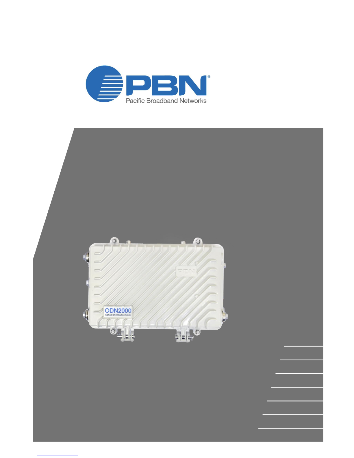
ODN2000/LE2000
Optical Distribution Node/Line Extender
with Two Amplified RF Ports
User Manual
Offices:
Australia, Melbourne: Tel. +61-3-8561-1400
China, Beijing: Tel. +86-10-5791-0655
Americas: Tel. +1-888-339-8805
EMEA, Netherlands: Tel. +31-36-536-8011
Email: [email protected]
Website: www.pbnglobal.com
©2016 Pacific Broadband Networks. All rights reserved.
Page 2

ODN2000/LE2000 User Manual
Pacific Broadband Networks Page 2 of 36
ODN2000/LE2000
Optical Distribution Node/Line Extender with
Two Amplified RF Ports
User Manual
Release Date
February 1, 2016
Document version
V0a
Document reference
PBN.ODN2000-Manual V0a-Released-1 Feb 16.pdf
Document status
Released
Prepared by
Pacific Broadband Networks
Prepared for
ODN2000/LE2000 Product Users
Page 3

ODN2000/LE2000 User Manual
Pacific Broadband Networks Page 3 of 36
Contents
1 Preface .......................................................................................................................................... 4
1.1 Main Contents ......................................................................................................................... 4
1.2 Technical Support ................................................................................................................... 4
2 Precautions .................................................................................................................................. 5
3 Introduction .................................................................................................................................. 6
3.1 Overview ................................................................................................................................. 6
3.2 Features .................................................................................................................................. 6
3.3 Specifications .......................................................................................................................... 7
3.4 Model Order Details ................................................................................................................ 9
4 Technical & Module Description .............................................................................................. 12
4.1 Technical Description ............................................................................................................ 12
4.2 Internal Layout ...................................................................................................................... 14
4.3 Power Module Panel............................................................................................................. 17
4.4 ODN-FR Top Panel ............................................................................................................... 18
4.5 ODN-RT Top Panel ............................................................................................................... 19
4.6 Attenuator/Equalizer Pad ...................................................................................................... 20
4.7 External RF Connectors & Mounting Holes ......................................................................... 22
5 Installation .................................................................................................................................. 24
5.1 Equipment Inventory ............................................................................................................. 24
5.2 Packaging and Transportation .............................................................................................. 24
5.3 Installation ............................................................................................................................. 24
5.3.1 Node Installation Pointers .............................................................................................. 24
5.3.2 Mounting ........................................................................................................................ 24
5.3.3 Cable Routing ................................................................................................................ 26
5.3.4 Optical Stub Cable ......................................................................................................... 27
5.3.5 Closing the Node............................................................................................................ 30
5.4 Module Installation & Removal ............................................................................................. 32
5.4.1 Module Removal ............................................................................................................ 32
5.4.2 Module Installation ......................................................................................................... 33
6 Product Warranty ...................................................................................................................... 35
Page 4

ODN2000/LE2000 User Manual
Pacific Broadband Networks Page 4 of 36
1 Preface
1.1 Main Contents
This User Manual consists of the following sections:
1 Preface
2 Precautions
3 Introduction
4 Technical & Module Description
5 Installation
6 Product Warranty
1.2 Technical Support
Please contact Pacific Broadband Networks qualified service personnel for all your enquiries
about this product.
Pacific Broadband Networks (PBN) Offices
Australia
Address: Suite 15, Building 3, 195 Wellington Road, Clayton, VIC 3168, Australia
Phone: +61-3-8561-1400
Fax: +61-3-9562-2957
Europe
Address: Argonweg 15,1362AA Almere, Netherlands
Phone: +31-36-536-8011
Fax: +31-36-536-4367
China
Address: Unit 403, Entrance C, Building No. 201 A-10, Jiuxianqiao Beilu, Chaoyang District,
Beijing, China
Phone: +86-10-5791-0655
Fax: +86-10-5791-0855
Americas
Phone: +1-888-339-8805
Website: www.pbnglobal.com
Email: [email protected]
Page 5

ODN2000/LE2000 User Manual
Pacific Broadband Networks Page 5 of 36
2 Precautions
General Warning
WARNING!
This product has an IP67 rating. It is suitable for outdoor applications.
To prevent fire, electrical shock, or permanent damage to the product do
not expose this unit to conditions outside its rating.
The product user manual should be read and understood before any units are put into
use.
Ensure the unit has adequate cooling and ventilation. The unit must be mounted with the
heat-dissipating fins vertically-oriented.
SC/APC 8° angle polished connectors must be used.
Always replace protective caps on optical connectors when not in use.
Dangerous voltages are present within the unit at all times.
Do not operate unit without all covers and panels properly installed.
Cleaning
Use only a damp cloth for cleaning front panel. Use a soft dry cloth to clean the top of unit. Do not
use any liquid cleaners of any kind.
Overloading or outage
Unplug the unit and refer all repairs to Pacific Broadband Networks’ qualified service personnel.
Only use approved electrical cords. Overloading wall outlets and extension cords may result in a
fire or electrical shock.
Servicing
Do not attempt to service this unit yourself.
Refer servicing to Pacific Broadband Networks’ qualified service personnel only.
Laser Radiation
WARNING!
Exposure to class 1M laser radiation is possible. Access should be
restricted to trained personnel only. Do not look directly at exposed fiber
or connector ends when handling optical equipment.
Page 6

ODN2000/LE2000 User Manual
Pacific Broadband Networks Page 6 of 36
3 Introduction
3.1 Overview
The small and adaptable ODN2000 Optical Distribution Node with two amplified RF ports has
been designed to affordably deliver interactive CATV and high capacity DOCSIS services. The
ODN2000 is a high performance network device engineered to provide the highest quality
transmission of HD video, data, and VoIP services.
The ODN2000 is currently equipped with a Gallium arsenide (GaAs) module that offers a
cost-effective and flexible solution to expand networks. The optical node offers two high power RF
outputs, each with over 1 GHz of bandwidth.
The ODN2000 deep-fiber node is perfect for the last mile in broadband networks. The small and
rugged design makes this unit ideal for fiber-to-the-apartment and fiber-to-the-curb applications.
Having versatile modular components allows the ODN2000 to be utilized in many different phases
of network deployment. As the network grows, the ODN2000/LE2000 can be upgraded.
Unmatched flexibility, combined with a robust housing, makes this a reliable product for designing
long-term HFC solutions. Additionally, Node+0 support allows for a reduction in amplifiers,
improved reliability, and lower maintenance costs, as well as additional options for future
cost-effective upgrades.
The optional DOCSIS transponder remotely monitors and manages the ODN2000 to simplify
system maintenance and reduce maintenance costs.
The LE2000 is the basic amplifier model and can be upgraded to a 2-port fiber node (into the
ODN2000) by adding the optional reverse transmitter module and forward receiver module.
3.2 Features
Advanced Gallium Arsenide (GaAs) RF hybrid technology provides excellent
performance with two individually amplified high-level outputs with more than 55 dBmV
each at 1000 MHz
High output power supports Node+0 architecture
Can be seamlessly upgraded from an RF amplifier (LE2000) to an optical node
(ODN2000)
Return-path lasers are available for 1310 nm or for CWDM applications on one return
fiber at 1470/1490/1510/1530/1550/ 1570/1590/1610 nm
Optical transmitter/receiver modules and RF amplifier can be individually installed,
removed, or replaced. The modular design reduces downtime and simplifies
maintenance
Standard attenuator/equalizer pad to control both attenuation and equalization
Page 7

ODN2000/LE2000 User Manual
Pacific Broadband Networks Page 7 of 36
Dedicated KS 5/8" AC input for remote power. 35-90 Vac power supply
Optional DOCSIS transponder for ODN2000 remote monitoring and management
Remotely (provisioned) or locally manageable and upgradeable
3.3 Specifications
Forward Path Optical Performance
Optical wavelength
1200-1610 nm
Input range
−5-3 dBm
Nominal design input
−1 dBm
OAGC (optical input)
−4-2dBm
Optical return loss
>50 dB
Forward Path RF Performance
Bandwidth
54 / 70 / 85-1000 MHz
RF flatness
±0.75 dB
Output level
> 50 dBmV @ 1000 MHz (ODN2xxx-A)1
> 55 dBmV @ 1000 MHz (ODN2xxx-B)2
Return loss
>16 dB
Impedance
75 Ω
RF output stability
±1 dB
Forward Path Optical Link Performance3
CNR (5 MHz NBW)
>53 dB
CSO
>65 dB
CTB
>68 dB
MER
>37 dB
BER
<1E−9
Return Path RF Performance
1
14 ± 1 dB slope from 85 to 1000 MHz. Optical input −4-+2 dBm, 4% OMI.
2
14 ± 1 dB slope from 85 to 1000 MHz. Optical input −4-+2 dBm, 4% OMI.
3
CNR, CSO, CTB, and MER are loaded with 30 NTSC+124 QAM256 or 30 PAL D/ K+85 QAM256; measured with
PBN referenced optical receiver with 10 km single-mode optical fiber 0 dBm.
BER is loaded with 30 NTSC+124 QAM256, 30 PAL D/K+85 QAM256, or 153 QAM256; measured with PBN
referenced optical receiver with 10 km single-mode optical fiber 0 dBm.
Page 8

ODN2000/LE2000 User Manual
Pacific Broadband Networks Page 8 of 36
Bandwidth
5-42 / 55 / 65 MHz
RF flatness
±0.75 dB
Input level
15-20 dBmV
Gain adjustment
1 dB step
Impedance
75 Ω
Return Path Optical Link Performance1
NPR≥ 30 dynamic
range
>25 dB
Optical output stability
±0.5 dBm
CNR
>48 dB
IMD2
<−52 dBm
OMI
6% @ 20 dBmV input
Connectors
Optical connectors
SC/APC2, FC/APC, E2000/APC
RF connectors
Cable Entry: 5/8" - 24 thread
Internal Connectors: 75 Ω Mini SMB
RF Test points: G-type – male
Generals
Power supply
35-90 Vac; 90-264 Vac mains
Power consumption
1Rx, 44 W; 1Rx+1Tx, 46 W
Operating temperature
−40 to 65°C (-40 to 149°F)
Storage temperature
−40 to 80°C (-40 to 176°F)
Dimensions (W×D×H)
235×143×307 mm (9.25 x 5.62 x 12.08 in)
Ship size (W×D×H)
310×260×400 mm (12.20 x 10.24 x 15.75 in.)
Weight
ODN2000, 5.7 kg (12.57 lb.); LE2000, 5.1 kg (11.24 lb.)
Ship weight
ODN2000, 6.3 kg (13.89 lb.); LE2000, 5.7 kg (12.57 lb.)
Enclosure IP rating
IP67
1
Use PBN RRAS-Q @ 0km fiber, -7 dBm input, 6% OMI.
2
Standard option. Contact a PBN Sales Representative for the availability of other options.
Page 9

ODN2000/LE2000 User Manual
Pacific Broadband Networks Page 9 of 36
3.4 Model Order Details
ODN2[P][Q][R]-[S]-[T][U][V][W]-[X]-[Y10]-[Z]
Optical Distribution Node with two amplified RF
ports
LE2[P][Q][R]-[S]-[T][U][V]
Line Extender with two amplified RF ports
Accessories
LE2[P][Q][R]-[S]-[T]
RF Amplifier
ODN20-FR-[W]-[Z]
Forward Path Optical Receiver
ODN20-RT-[W]-[Y1]-[Z]
Return Path Optical Transmitters (5-200 MHz)
Options
P
Type: 0 (RF PAD plug-in)
Q
Backplane Board Version: 0 (Basic Version)
R
Output Port Number: 1 (One port output); 2 (Two port output)
S
HW Performance1:
A > 50 dBmV @ 1000 MHz
B > 55 dBmV @ 1000 MHz
T
Diplexers
0 No diplexers
1 42/54 MHz
2 55/70 MHz
3 65/85 MHz
U
DOCSIS Transponder: 0 (Optional accessory)
V
Power Supply
1
35-90 Vac
2
50-110 Vac
3
90-264 Vac with power plug for CN
4
90-264 Vac with power plug for AU
5
90-264 Vac with power plug for EU
1
30 NTSC+124 QAM256 or 30 PAL D/K+85 QAM256; measured with PBN optical receiver with 10 km
single-mode optical fiber, 0 dBm; CSO>60 dB; CTB>60 dB.
Page 10

ODN2000/LE2000 User Manual
Pacific Broadband Networks Page 10 of 36
6
90-264 Vac with power plug for UK
7
90-264 Vac with power plug for US
W
Optical Connector
S (SC/APC)1; F (FC/APC); E (E2000/APC)
X
Forward Path Receiver
0 No receiver
1 One receiver
Y10
Return Laser Transmitter
0 No return transmitter
A 1310 nm DFB laser, 0 dBm (1 mW)
B 1310 nm DFB laser, 3 dBm (2 mW)
C 1310 nm DFB laser, −4 dBm (0.4mW)
N 1470 nm CWDM DFB laser, 3 dBm (2mW)
P 1490 nm CWDM DFB laser, 3 dBm (2mW)
Q 1510 nm CWDM DFB laser, 3 dBm (2mW)
R 1530 nm CWDM DFB laser, 3 dBm (2mW)
S 1550 nm CWDM DFB laser, 3 dBm (2mW)
T 1570 nm CWDM DFB laser, 3 dBm (2mW)
U 1590 nm CWDM DFB laser, 3 dBm (2mW)
V 1610 nm CWDM DFB laser, 3 dBm (2mW)
Z
Model Number: 1
Table 3-1 Return laser transmitter order examples
Code (Y10)
Description
00
No return transmitter
C0
One return transmitter; CWDM DFB 1310 nm, 0.4 mW
Q0
One return transmitter, CWDM DFB 1510 nm, 2 mW
1
Standard option. Contact a PBN Sales Representative for the availability of other options.
Page 11

ODN2000/LE2000 User Manual
Pacific Broadband Networks Page 11 of 36
Other Accessories
High Pass Filters
ODN20-HPF-54
54-1000 MHz
ODN20-HPF-70
70-1000 MHz
ODN20-HPF-85
85-1000 MHz
Low Pass Filters
ODN20-LPF-42
5-42 MHz
ODN20-LPF-55
5-55 MHz
ODN20-LPF-65
5-65 MHz
RF Diplexers
ODN20-DPL-4254
42 / 54 MHz
ODN20-DPL-5570
55 / 70 MHz
ODN20-DPL-6585
65 / 85 MHz
Power Supply
ODN20-PS-90
35-90 Vac
ODN20-PS-264-CN
90-264 Vac with power supply for CN
ODN20-PS-264-AU
90-264 Vac input power supply for AU
ODN20-PS-264-EU
90-264 Vac input power supply for EU
ODN20-PS-264-UK
90-264 Vac input power supply for UK
ODN20-PS-264-US
90-264 Vac input power supply for US
Attenuator/equalizer pad (0-1000 MHz):
ODN20-ATT-xx
xx = 0 dB to 30 dB in 1 dB steps1
1
If the pad is used as an equalizer, "xx" indicates an equalization value. If the pad is used as an attenuator, "xx"
indicates an attenuation value.
Page 12
ODN2000/LE2000 User Manual
Pacific Broadband Networks Page 12 of 36
4 Technical & Module Description
4.1 Technical Description
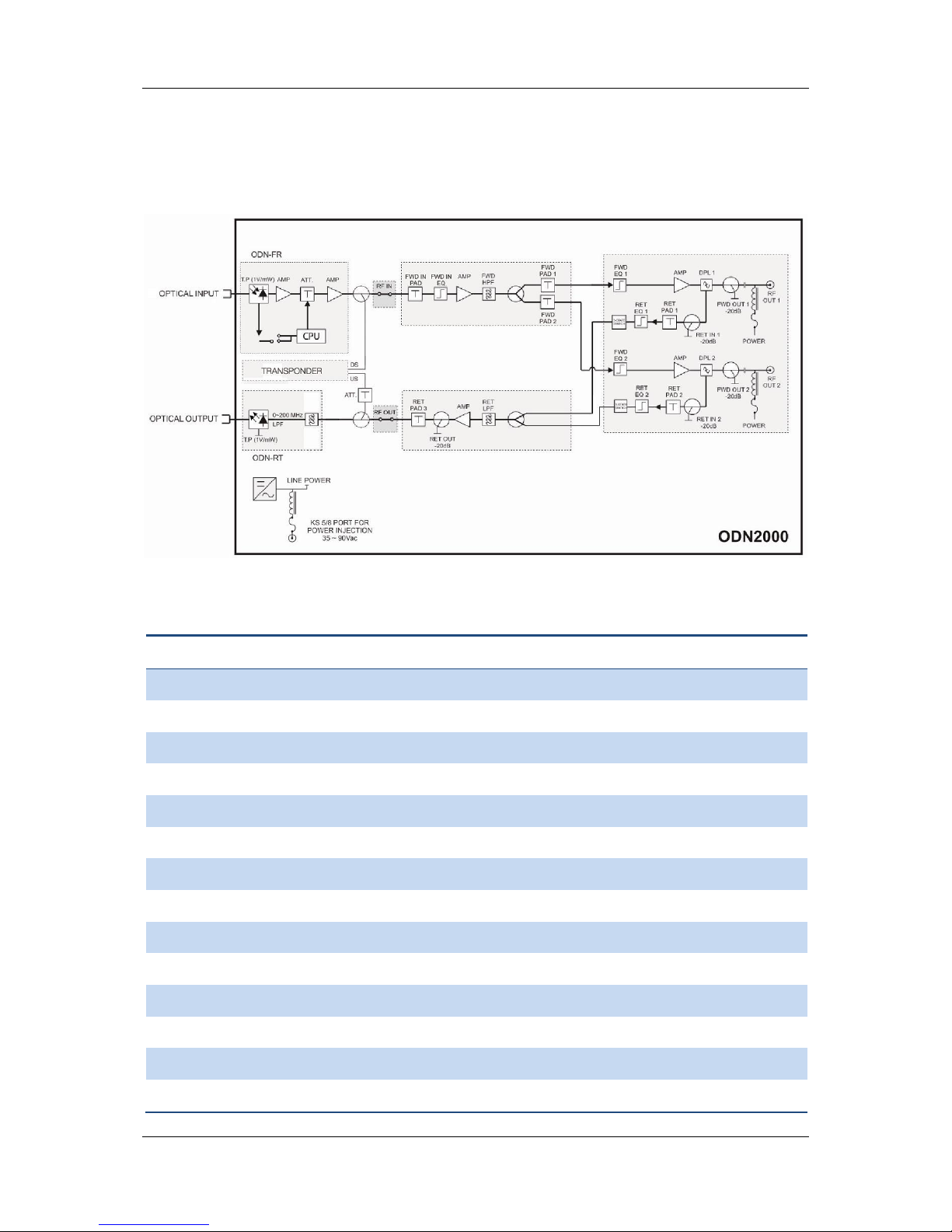
Figure 4-1 ODN2000 Block Diagram
Table 4-1 ODN2000 node circuit components
#
Part name
Description
1
OPTICAL INPUT
Optical input signal
2
ODN-FR
Forward path receiver
3
T.P. (1V/mW)
Optical power test point (1 V/mW)
4
AMP
Amplifier
5
ATT
Attenuator
6
CPU
Central processing unit
7
RF IN
RF input
8
FWD IN PAD
Forward path attenuator
9
FWD IN EQ
Forward path equalizer
10
FWD HPF
Forward path high pass filter
11
FWD PAD 1
Port 1 forward path attenuator
12
FWD PAD 2
Port 2 forward path attenuator
13
FWD EQ 1
Port 1 forward path equalizer
14
FWD EQ 2
Port 2 forward path equalizer
Page 13

ODN2000/LE2000 User Manual
Pacific Broadband Networks Page 13 of 36
#
Part name
Description
15
DPL 1
Port 1 diplexer
16
DPL 2
Port 2 diplexer
17
FWD OUT 1
Port 1 forward path RF output test point (−20dB)
18
FWD OUT 2
Port 2 forward path RF output test point (−20dB)
19
POWER
Power feed switch for subordinate equipment
20
RF OUT 1
Port 1 RF output signal
21
RF OUT 2
Port 2 RF output signal
22
RET IN 1
Port 1 return path RF input test point (−20dB)
23
RET IN 2
Port 2 return path RF input test point (−20dB)
24
RET PAD 1
Port 1 return path attenuator
25
RET PAD 2
Port 2 return path attenuator
26
RET EQ 1
Port 1 return path equalizer
27
RET EQ 2
Port 2 return path equalizer
28
INGRESS CONTROL SWITCH
3-state switch (0 dB, 6 dB, 31.5 dB)
29
RET LPF
Return path low pass filter
30
RET OUT
Forward path RF output test point (−20dB)
31
RET PAD 3
Port 3 return path attenuator
32
RF OUT
RF output
33
ODN-RT
Return path optical transmitter
(return laser transmitter)
34
LPF
Low pass filter
35
ATT.
Voltage controlled attenuator
36
TRANSPONDER
Network management transponder
37
DS
Downstream
38
US
Upstream
39
OPTICAL OUTPUT
Optical output signal
40
LINE POWER
(Node) power supply
41
KS 5/8 PORT FOR POWER INJECTION 35-90
Vac
KS 5"/8" port for 35-90 Vac power supply
Page 14
ODN2000/LE2000 User Manual
Pacific Broadband Networks Page 14 of 36
4.2 Internal Layout
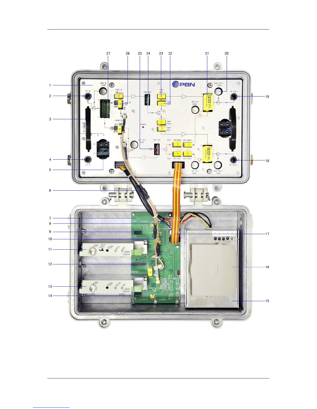
Figure 4-2 ODN2000 Internal Layout
Page 15

ODN2000/LE2000 User Manual
Pacific Broadband Networks Page 15 of 36
Table 4-2 ODN2000 components and their functions
#
Part name
Description
1
RF amplifier
2
RF input port
Used with an LE2000 amplifier
3
Handle
4
60 Vac power input
60 Vac power supply
5
Breakers
Plug-in, blade-type fuses to allow internal (F3, F4)
or external (F1, F2) power.
6
Power cord
7
Backplane
8
Forward path transmission line
9
Forward path receiver input - slave (FRS)
Temporarily unavailable
10
Return path transmission line
11
Forward path receiver input - master (FRM)
12
NMTD
DOCSIS network management transponder port
13
Return path receiver input - master (RTM)
14
Return path receiver input - slave (RTS)
Temporarily unavailable
15
Power module
16
Optical fiber module
17
Data cable
18
Port 2 RF output
19
Port 1 RF output
20
RF test point
21
Diplexer
22
Attenuator
23
Equalizer
24
High pass filter
25
Low pass filter
26
L-shaped port for attenuator pad
For LE2000, plug in the attenuator pad
horizontally.
For ODN2000, plug in the attenuator pad vertically
(as shown in Figure 4-2).
27
Diplexer
Used in an LE2000 amplifier
Page 16

ODN2000/LE2000 User Manual
Pacific Broadband Networks Page 16 of 36
Note:
The item names given in Section 4.1 (RF IN, FWD IN EQ, RET PAD1, etc.) apply to ODN2000 RF
amplifier components and are not repeated here. See Section 4.1 Technical Description for more
details.
Due page space limitations, only one component is marked when there are several components of
the same type.
Page 17
ODN2000/LE2000 User Manual
Pacific Broadband Networks Page 17 of 36
4.3 Power Module Panel
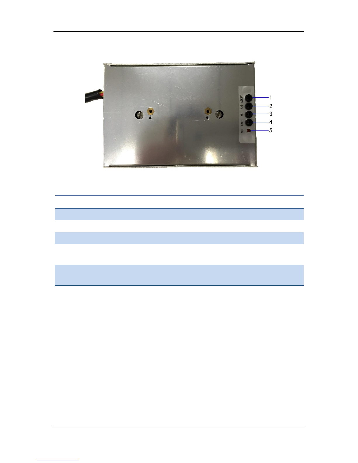
Figure 4-3 Power Module
Table 4-3 Power module panel components and their functions
#
LED Indicator
Description
1
AC Input Voltage Test Point (AC60V)
Test 60 V and 220 V AC input voltage
2
DC Output Voltage Test Point (24V)
Test 24 V DC output voltage
3
DC Output Voltage Test Point (8V)
Test 8 V DC output voltage
4
Ground Point (GND)
A ground reference point to measure input and
output voltages
5
Power LED (LED)
OFF - no power;
GREEN - module powered.
Page 18
ODN2000/LE2000 User Manual
Pacific Broadband Networks Page 18 of 36
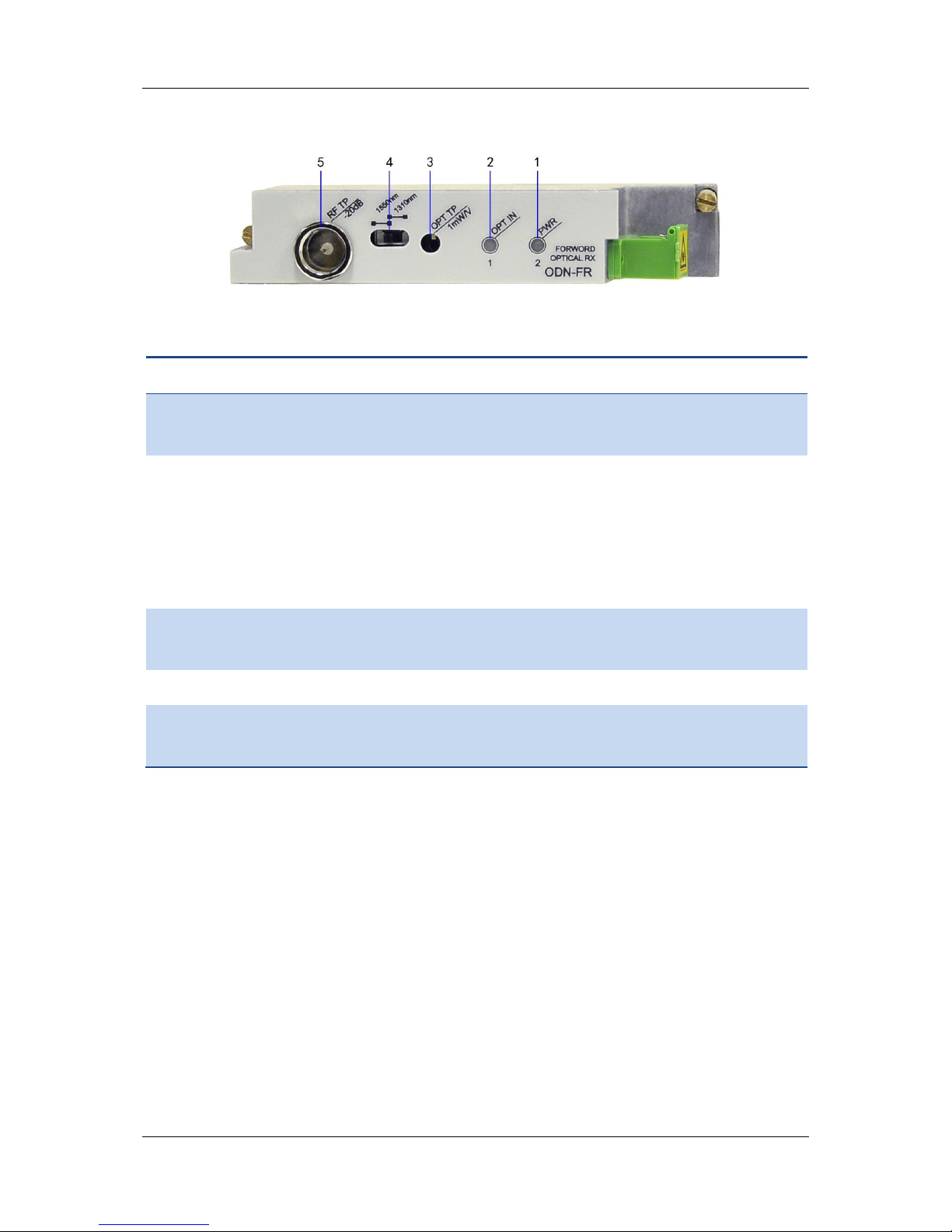
4.4 ODN-FR Top Panel
Figure 4-4 ODN-FR Top Panel
Table 4-4 ODN-FR top panel components and their functions
Item
Part name
Function
1
Power LED
OFF - no power;
GREEN - module powered.
2
OPT IN LED
OFF - no alarm state;
GREEN - receiver optical power level is within range of −2 to 2 dBm;
AMBER - receiver optical power is slightly outside of range: too low or high
(−2 to −5 dBm or 2 to 3 dBm);
RED - receiver optical power is too low or high (≤−5dBm or ≥3dBm).
3
Optical Power Test Point
(OPT TP)
1 V/mW
4
Wavelength Switch
Switches between 1550 nm and 1310 nm.
5
RF Test Point
−20 dB test point for checking the FR output level. It is rated as -20dB from
the actual output level.
Page 19
ODN2000/LE2000 User Manual
Pacific Broadband Networks Page 19 of 36
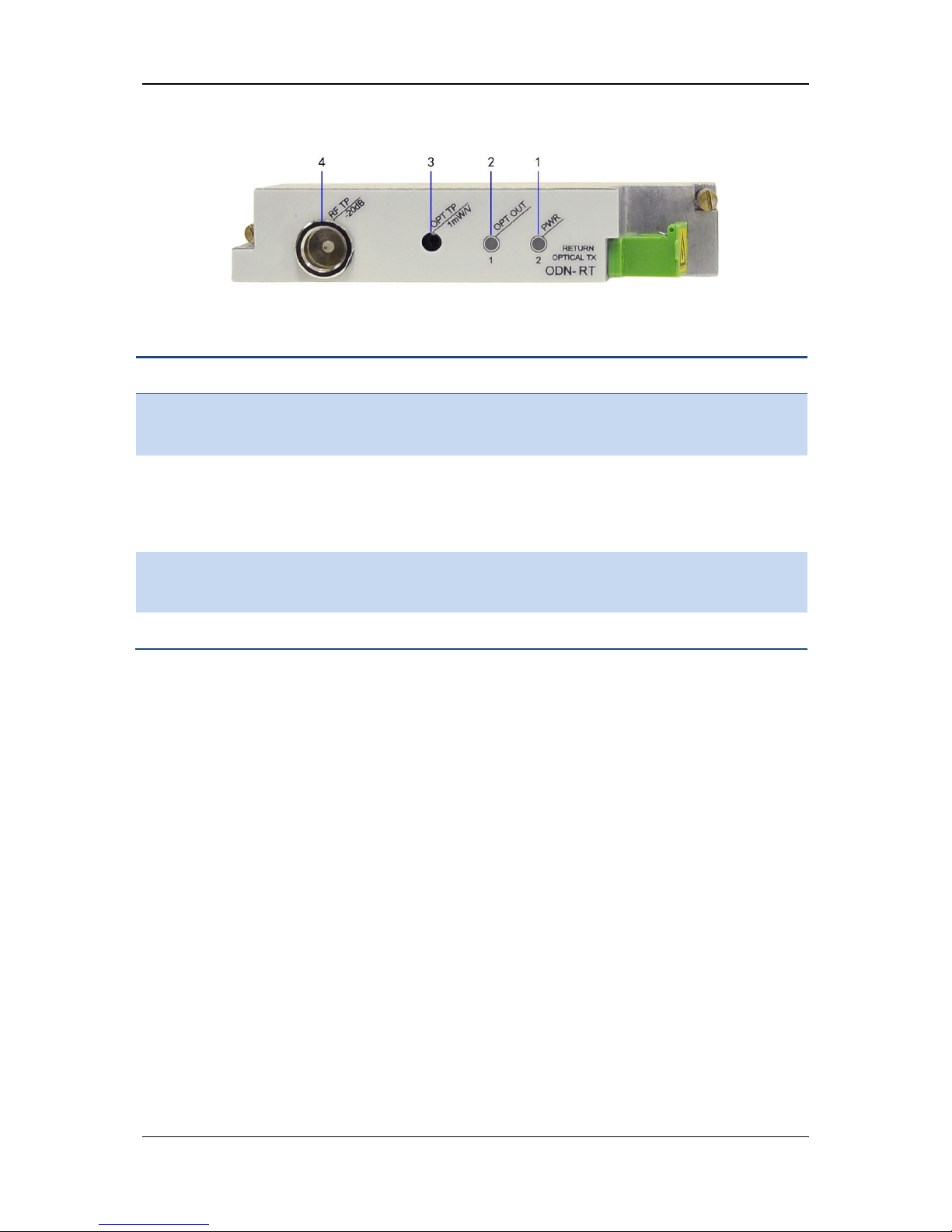
4.5 ODN-RT Top Panel
Figure 4-5 ODN-RT Top Panel
Table 4-5 ODN-RT top panel components and their functions
Item
Part name
Function
1
Power LED
OFF - no power;
GREEN - module powered.
2
OPTICAL OUTPUT
OFF - no power;
GREEN - transmitter optical output signal is within range;
RED - no or weak optical output signal.
3
Optical Power Test Point
(OPT TP)
1 V/mW
4
RF Test Point
−20 dB test point for checking the RT output level
Page 20
ODN2000/LE2000 User Manual
Pacific Broadband Networks Page 20 of 36
4.6 Attenuator/Equalizer Pad
Figure 4-6 Attenuator/Equalizer Pad
Attenuator pad ODN20-ATT-xx is used in both ODN2000/LE2000 in RF output attenuation and
equalization. If the pad is used as an equalizer, "xx" indicates an equalization value. If the pad is
used as an attenuator, "xx" indicates an attenuation value.
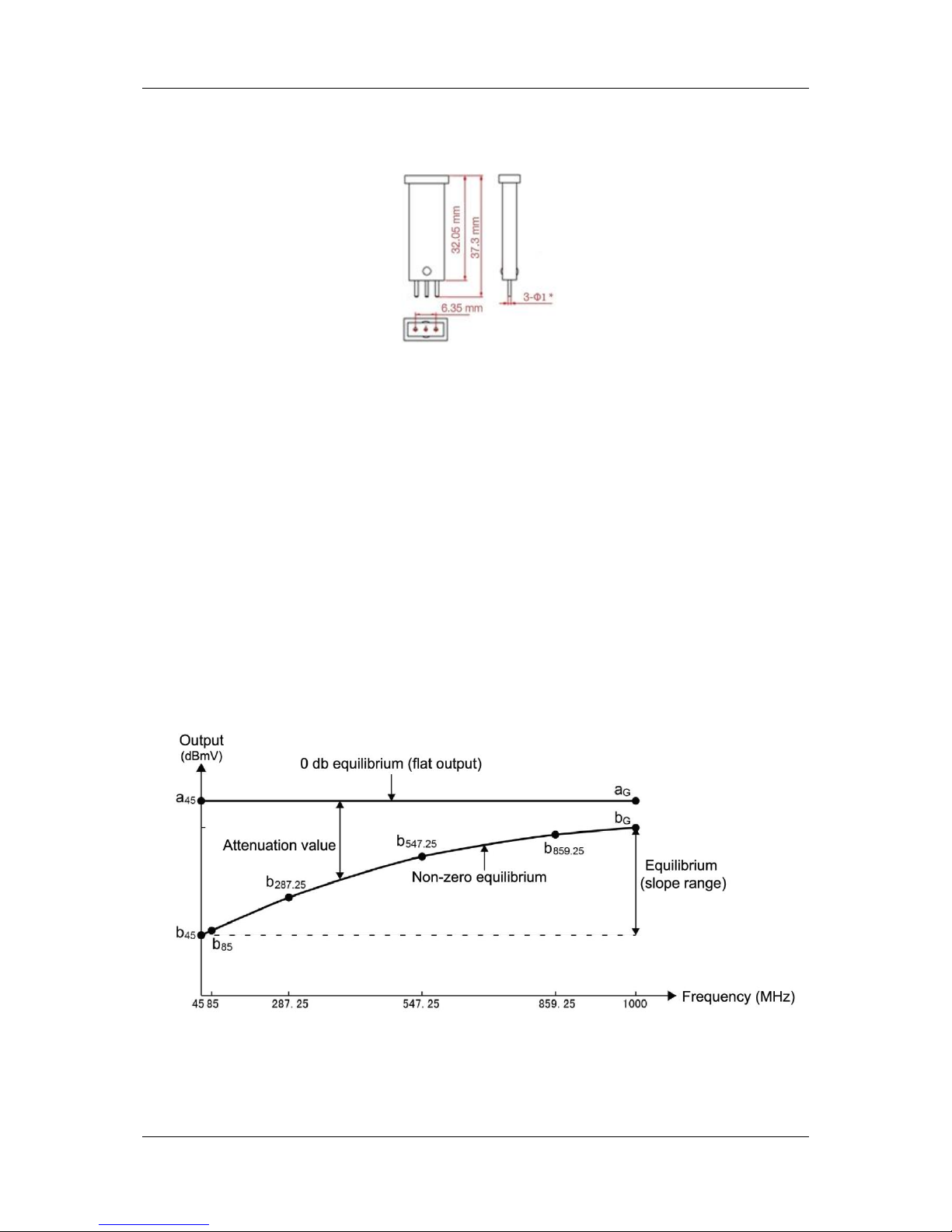
Figure 4-7 shows equalization slope characteristics. If an equalizer value "xx" is set to zero (0 dB
equalization), there will be no RF attenuation or frequency-dependent variations in RF output
levels. If an equalizer value other than 0 dB is used, there will be some inherent insertion loss
introduced along with the equalization slope. The slope value between the lowest (b45) and
highest (bG) frequencies corresponds to the equalization value. As the use of an equalization value
other than 0 dB may cause slight RF output attenuation even at the highest frequency, RF output
level at bG may be lower than that at aG.
Table 4-6 outlines the approximate attenuation introduced by ODN20-ATT-08 and ODN20-ATT-12
across a range of frequencies.
Figure 4-7 Equalization Slope Characteristics
Page 21

ODN2000/LE2000 User Manual
Pacific Broadband Networks Page 21 of 36
Table 4-6 Attenuation (dB) introduced by ODN20-ATT-08 and ODN20-ATT-12 equalizers
Pad Type
Reference
Frequency
ODN20-ATT-08
ODN20-ATT-12
85 MHz
7.4
11.2
287.25 MHz
5.3
7.7
547.25 MHz
2.8
3.8
859.25 MHz
0.8
0.9
1000 MHz
0.2
0.2
Page 22
ODN2000/LE2000 User Manual
Pacific Broadband Networks Page 22 of 36
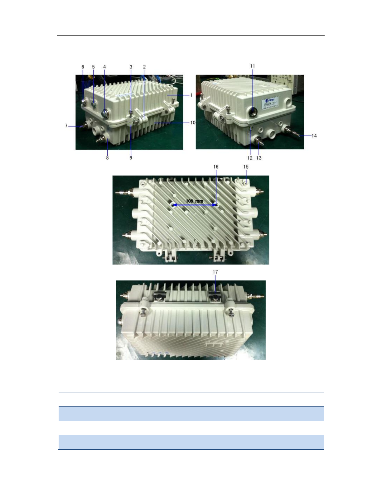
4.7 External RF Connectors & Mounting Holes
Figure 4-8 ODN2000 External RF Connectors & Mounting Holes
Table 4-7 ODN2000 external RF connectors & mounting holes
#
Part name
Description
1
Front of the node casing
2
Hinges
3
Pedestal mounting bolts
4
Page 23

ODN2000/LE2000 User Manual
Pacific Broadband Networks Page 23 of 36
#
Part name
Description
4
Optical input port
5
Modem port
6
Optical output port
7
RF input port
Used in an LE2000 amplifier
8
60 Vac power input
For 60 V power supply
9
Mounting holes for lid-to-base bolts
Located on the front and back of the node casing (4 on each side)
10
Back of the node casing
11
220 Vac power input
For 220 V power supply
12
Ground point
13
Port 2 RF output
14
Port 1 RF output
15
Mounting holes
For wall mounting
16
Mounting holes
For wall mounting (distance between the mounting holes: 106
mm)
17
Strand clamps
Used for strand mounting and have grooves for suspension
cables
Page 24

ODN2000/LE2000 User Manual
Pacific Broadband Networks Page 24 of 36
5 Installation
5.1 Equipment Inventory
On receiving your new ODN2000 or LE2000, carefully unpack and examine the contents for any
missing or damaged parts (Table 5-1). Refer to your warranty if loss or damage has occurred.
Table 5-1 Packaging content
Item
Description
Qty
Device purchased (ODN2000 or LE2000)
1
Certificate of Performance (includes test result
sheet)
1
5.2 Packaging and Transportation
Use only the original packaging of the ODN2000/LE2000 when transporting.
Keep all boxes and packaging, designed specifically to protect the equipment, for future transport
of the ODN2000/LE2000.
5.3 Installation
5.3.1 Node Installation Pointers
A clearance of 50 mm must be left between all sides of the node and any obstruction.
Avoid installing the node near any sources of water, such as air-conditioning drain outlets
or roof gutters. If it must be installed near water, a waterproof board should be installed
35 cm above the node.
The node MUST be properly grounded.
Ensure that the attenuator/equalizer pads are installed in the correct orientation and
pushed in firmly. Frequency response and RF performance will be affected if the pads are
not installed correctly.
Ensure that the pads are installed in the correct orientation and pushed in firmly. The
internal RF PADs within the ODN2000 and LE2000 are terminated with 75 Ω mini-SMB
connectors. These connectors must be handled carefully as they can be easily damaged.
5.3.2 Mounting
Page 25
ODN2000/LE2000 User Manual
Pacific Broadband Networks Page 25 of 36
5.3.2.1 Strand Mounting
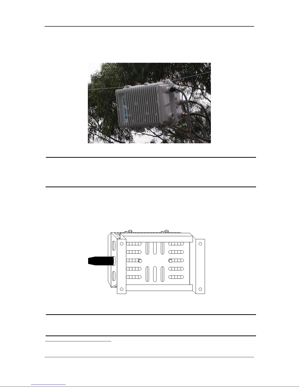
Each ODN2000 node has two strand clamps with grooves (Item 17 in Figure 4-8). The ODN2000
node can be mounted via a suspension cable running through the two clamps.
Figure 5-1 Strand Mounting1
Note:
Do not hang the node from any wires or electrical cables. Use only a dedicated suspension cable
that is rated to hold the weight of the node.
5.3.2.2 Wall Mounting
An ODN2000 node can be mounted on the wall via two mounting holes (located 106 mm from one
another) on the rear of the node. There should be enough clearance left below the node to allow
maintenance and troubleshooting.
Figure 5-2 Wall Mounting
Note:
Mounting brackets and associated hardware are NOT supplied by PBN.
1
The figure shows an ODN4P node for illustration purpose; ODN2000 nodes are strand-mounted in the same
way.
Page 26
ODN2000/LE2000 User Manual
Pacific Broadband Networks Page 26 of 36
5.3.3 Cable Routing
5.3.3.1 Applying AC Power
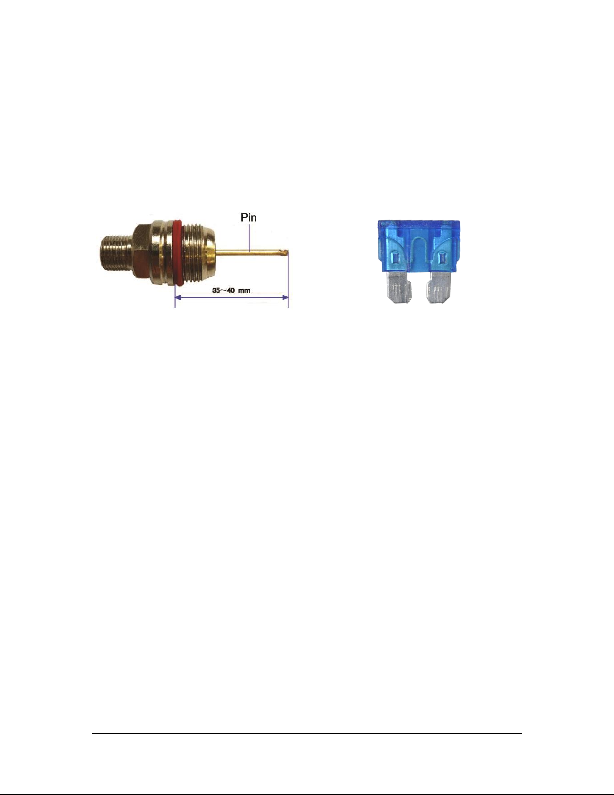
The ODN2000 may be directly line powered via the dedicated 60V AC power input. When
plugging in the power connector, please make sure that the center pin is between 35 and 40 mm in
length when measured from the seating area of the connector to the tip of the center pin. If the pin
is longer, there is a risk of damaging the ODN2000.
A fuse must be plugged into breaker F4 to provide internal power.
Figure 5-3 The Center Pin of a Connector
Figure 5-4 Fuse
Follow the procedure below to supply 60 Vac AC power to the ODN2000:
a) After removing the protective cap, insert the pin connector into the ODN2000 power
supply port. Ensure that the pin is connected into the power supply on the PCB rated at
60 Vac. Before inserting the connector, affix an O-ring to seal the connection and prevent
water from entering.
b) Tightly screw the connector into the power supply port.
c) Attach the 60 Vac power adapter cable to the connector.
d) Ensure that a fuse is inserted into breaker F4.
e) Verify that the power module status LED is ON (GREEN). GREEN indicates that the
power module is on; if the LED indicator is OFF, check for any problems with the power
adapter or power supply.
f) Verify that the forward path receiver and return path transmitter power supply LED
indicators (PWR) are ON (GREEN). GREEN indicates that the module is powered; if the
LED indicator is OFF, check whether the power module, power adapter, and power
supply are functioning normally.
5.3.3.2 RF Input/Output Cable Routing
The ODN2000 RF output ports 1 and 2 are used for forward path output signals and return path
input signals. External RF connectors should be inserted into these ports. Please make sure that
the center pin is between 35 and 40 mm in length when measured from the seating area of the
connector to the tip of the center pin (Figure 5-3 in Section 5.3.3.1 Applying AC Power).
If the node is used to supply power to cascaded equipment, insert fuses into breakers F1 and F2
as required for the RF output ports.
Page 27

ODN2000/LE2000 User Manual
Pacific Broadband Networks Page 27 of 36
Note:
If outgoing power is not needed, remove the fuses to avoid damaging any internal components.
5.3.4 Optical Stub Cable
General Warning
CAUTION:
Equipment installers are responsible for the correct installation of
optical stub cables, optical fibers, and all RF terminators. Failure to
properly adhere to the instructions and recommendations herein may
affect RF performance or cause the optical node to fail. This type of
damage voids the warranty provided by Pacific Broadband Networks.
Optical connector ferrules should be no longer than 1.5 cm in order not
to affect the node operation.
Note:
Heat the ODN2000 node prior to installation of optical stub cables. Make sure to run enough
optical fiber length inside the node so that it is not taut when opening the case.
The optical modulation index (OMI) of a PBN LTM13 laser transmitter module is 4%1 (factory
setting).
5.3.4.1 Optical Input Port Cable
The optical input cable is connected to the ODN-FR via the ODN2000 optical input port. The
ODN-FR allows an optical input level between −5dBm and -3dBm. It has OAGC range between
−4dBm and -2 dBm and output level of 20 dBmV.
Optical Input Port Cable
Follow the procedure below to install the optical input cable:
a) Before connecting fiber to the receiver, measure the optical input level with an optical
power meter. The optical input level should be between −5 dBm and +3 dBm (level
between−2dBm and -2 dBm is recommended). Higher optical input levels may cause
damage to the optical receiver tubes.
b) Insert the optical cable into the ODN2000 optical input port.
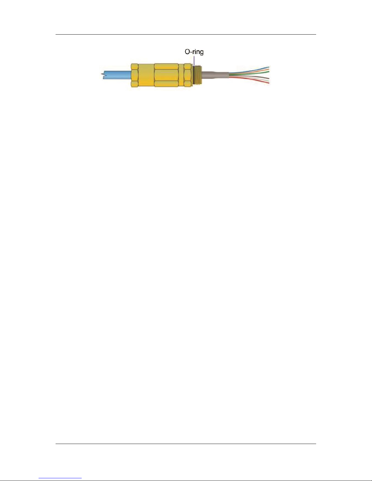
c) Mount the waterproof conduit and place the fiber cable end in the optical fiber module.
The sealing O-ring must be on the connector and in good condition. Apply heat shrink
tubing or sealing tape.
1
Test conditions: 77 channels, NTSC
Page 28
ODN2000/LE2000 User Manual
Pacific Broadband Networks Page 28 of 36
Figure 5-5 Optical Stub Cable Sealing
d) Use a multi-meter to measure the actual optical input level at the ODN-FR optical power
test point (OPT TP). The conversion from optical input level (WIN) in dBm to Volts at the
optical input test point (V
TPI
) is:
𝑊𝐼𝑁= 10 lg 𝑉
𝑇𝑃𝐼
e) Ensure that the optical input level is within the acceptable range. If it is too low or too high
(indicated by an ORANGE or RED receiver optical power LED indicator), adjust the
optical input level and repeat the steps d-e until it is within the acceptable range (indicated
by a GREEN receiver optical power LED indicator).
f) Measure RF output level at the ODN-FR RF output test point. The forward RF output
level should be 20 dBmV.
Setting the Forward RF Output Level & Slope
Follow the procedure below to set up the forward RF output level and slope:
a) ODN-FR RF output is the RF input for the RF amplifier. Factory set to 20 dBmV at 547.25
MHz.
b) Place equalizers in the “FWD IN EQ”, "FWD EQ1", and "FWD EQ2" locations on the RF
amplifier. "FWD IN EQ" is the main circuit equalizer and can be simultaneously used for
equalization of two output ports. "FWD EQ1" and "FWD EQ2" are branch circuit
equalizers and are used separately for equalization of second output ports. Set
equalization values to 0 dB to ensure a flat forward RF output level.
c) Place 0 dB attenuators in the "FWD IN PAD", "FWD PAD1", and "FWD PAD2" locations
on the RF amplifier. Measure RF output levels at the "FWD OUT1" and "FWD OUT2" test
points and select the desired equalization slope values and characteristics.
d) Place attenuators in the “FWD IN PAD”, "FWD PAD1", and "FWD PAD2" locations on the
RF amplifier. Output test point should be 20dB below each of the main output ports.
Measure to ensure that the level at this point is no more than 50dBmV at 547.25 MHz.
e) Measure RF output levels at the "FWD OUT1" and "FWD OUT2" test points to check
whether they meet requirements.
f) If Ports 1 and 2 are used as a forward power feed, please insert fuses into respective
locations (F1 and F2).
Page 29

ODN2000/LE2000 User Manual
Pacific Broadband Networks Page 29 of 36
Note:
Please terminate unused port with a 75 Ω terminator.
Setup Example for Forward RF Output Levels & Slope
Condition
Output Requirements
Optical input level of −1 dBm
Required output power for Ports 1 & 2 is 45 dBmV at 547.25 MHz
Equalization on Ports 1 & 2 is to be 0 dB
Port 1 is used for providing power
The following setup is recommended:
a) ODN-FR optical input level is set to the nominal level of −1 dBm. ODN-FR RF output level is
set to 20 dBmV at 547.25 MHz, i.e., the amplifier's RF input level is 20 dBmV at 547.25 MHz.
b) Place 0 dB equalizers in the “FWD IN EQ”, "FWD EQ1", and "FWD EQ2" locations on the
RF amplifier.
c) Place 0 dB attenuators in the "FWD IN PAD", "FWD PAD1", and "FWD PAD2" locations
on the RF amplifier. Measure Port 1 and Port 2 RF output levels at the "FWD OUT1" and
"FWD OUT2" test points. For this example, assume the RF levels are found to be
30 dBmV at 547.25 MHz, i.e., RF output levels present at Ports 1 and 2 are 50 dBmV at
547.25 MHz.
d) Place a 5 dB attenuator in the "FWD IN PAD" location on the RF amplifier and measure
RF output levels. For this example, assume the RF levels are found to be 25 dBmV at
547.25 MHz, i.e., RF output levels present at Ports 1 and 2 are 45 dBmV at 547.25 MHz.
e) Place a 15 Amp fuse in the F1 breaker to allow power to pass through Port 1.
5.3.4.2 Optical Output Port Cable
Setting the Return RF Input Level & Slope
Prior to connecting the optical cable to the optical output port, use the following procedure to set
the return RF input level and slope:
a) Measure return RF input levels at "RET IN1" and "RET IN2" test points.
b) Place equalizers in the "RET EQ1" and "RET EQ2" locations on the RF amplifier. "RET
EQ1" and "RET EQ2" are branch circuit equalizers that are used separately for
equalization of RF input and output signals. Set equalization values to 0 dB to ensure a
flat return RF input level.
c) Place 0 dB attenuators in the "RET PAD1", "RET PAD2", and "RET PAD3" locations on
the RF amplifier. Measure return path output levels at the "RET OUT" test point.
d) Compare RF input and output levels obtained from "RET IN1" and "RET OUT" test points,
as well as those obtained from "RET IN2" and "RET OUT" test points. Determine
attenuation values and slope characteristics for "RET EQ1” and "RET EQ2" equalizers.
Page 30

ODN2000/LE2000 User Manual
Pacific Broadband Networks Page 30 of 36
e) Based on the selected equalization parameters, set the attenuation values for "RET
PAD1", "RET PAD2", and "RET PAD3" attenuators to achieve 37 dBmV1 ODN-RT RF
input level. Consider the loss introduced by the return combiner.
f) Place attenuators with selected attenuation values in the "RET PAD1", "RET PAD2", and
"RET PAD3" locations.
g) The RF test point on the ODN-RT should be used to verify that the correct RF signal level
is being received. If the RF input level deviates considerably from the required level of 37
dBmV, repeat steps e-g.
Note:
RF amplifier's return gain is set to 26 dB.
Optical Output Port Cable
Procedure to install the optical output cable:
a) Prior to connecting the optical cable to the optical output port, use a multimeter to
measure the actual optical output level at the ODN-RT optical power test point (OPT TP).
The conversion from optical output level (W
OUT
) in dBm to Volts at the optical output test
point (V
TPO
) is:
𝑊
𝑂𝑈𝑇
= 10 lg 𝑉
𝑇𝑃𝑂
b) Compare the optical output level obtained from the test point with the nominal value set
for ODN-RT. If the difference between the two is small, proceed to the next step; if the
difference is big, please contact PBN’s qualified service personnel.
c) Connect the optical fiber to the ODN2000 optical output port.
d) Mount the "waterproof pipe" and place the fiber cable end in the optical fiber module. The
sealing O-ring must be on the connector and in good condition. Apply heat shrink tubing
or sealing tape (Figure 5-5).
5.3.5 Closing the Node
Before commissioning the node, please check that the following screws are firmly and securely
tightened.
Two mounting screws on each optical receiver.
Two mounting screws on each optical transmitter.
The mounting screws for any optional modules.
The 2 main chassis mounting screws.
Some of the module mounting screws have metal spacers. They should be checked to ensure that
they are present and are secured so they are screwed all the way in and are touching the module.
1
The optimal RF input level for the return-path transmitter is 37 dBmV at 6% OMI.
Page 31
ODN2000/LE2000 User Manual
Pacific Broadband Networks Page 31 of 36
When installing a module, tighten the mounting screws in steps.
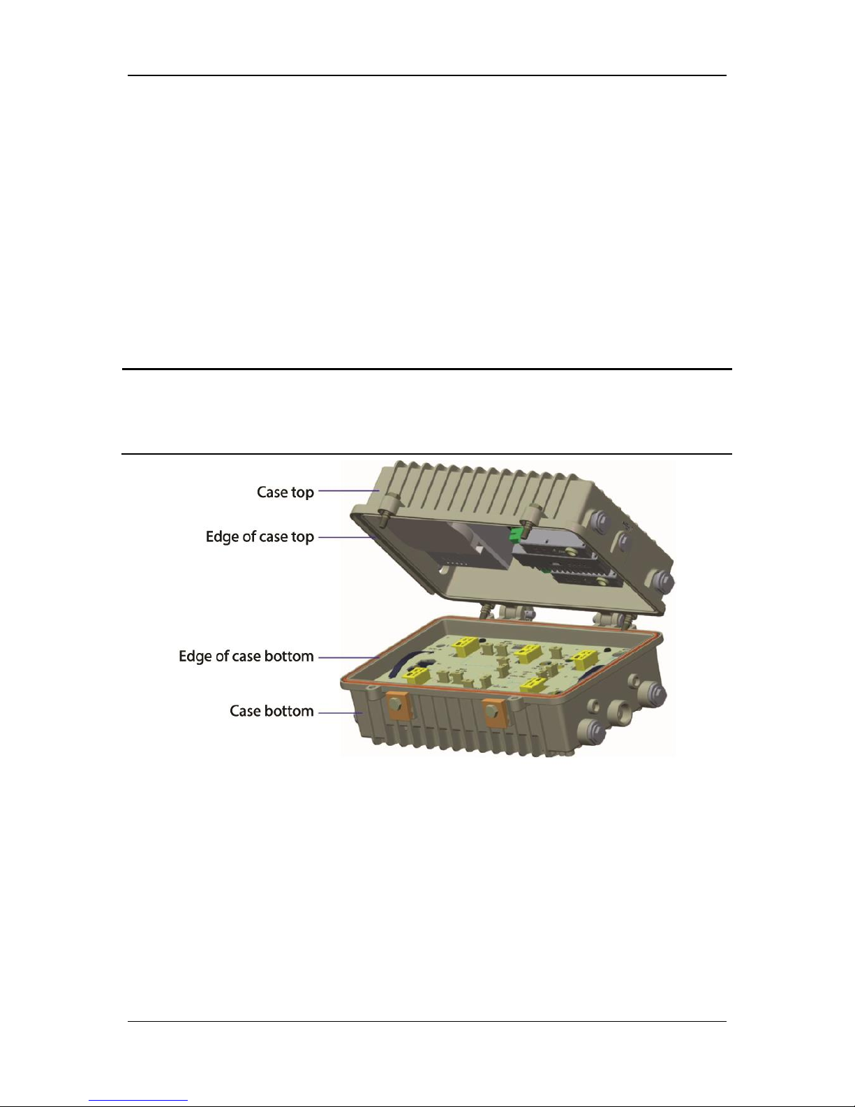
Prior to closing the node, inspect the surfaces of the metal mating edge and the opposing rubber
sealing gasket. The ridge must be continuous and not damaged or scratched in any way. The
rubber-sealing gasket must also be in good condition. Ensure all cables and optical fibers are clear
of the edges of the lid and base. Refer all repairs to Pacific Broadband Networks’ qualified service
personnel.
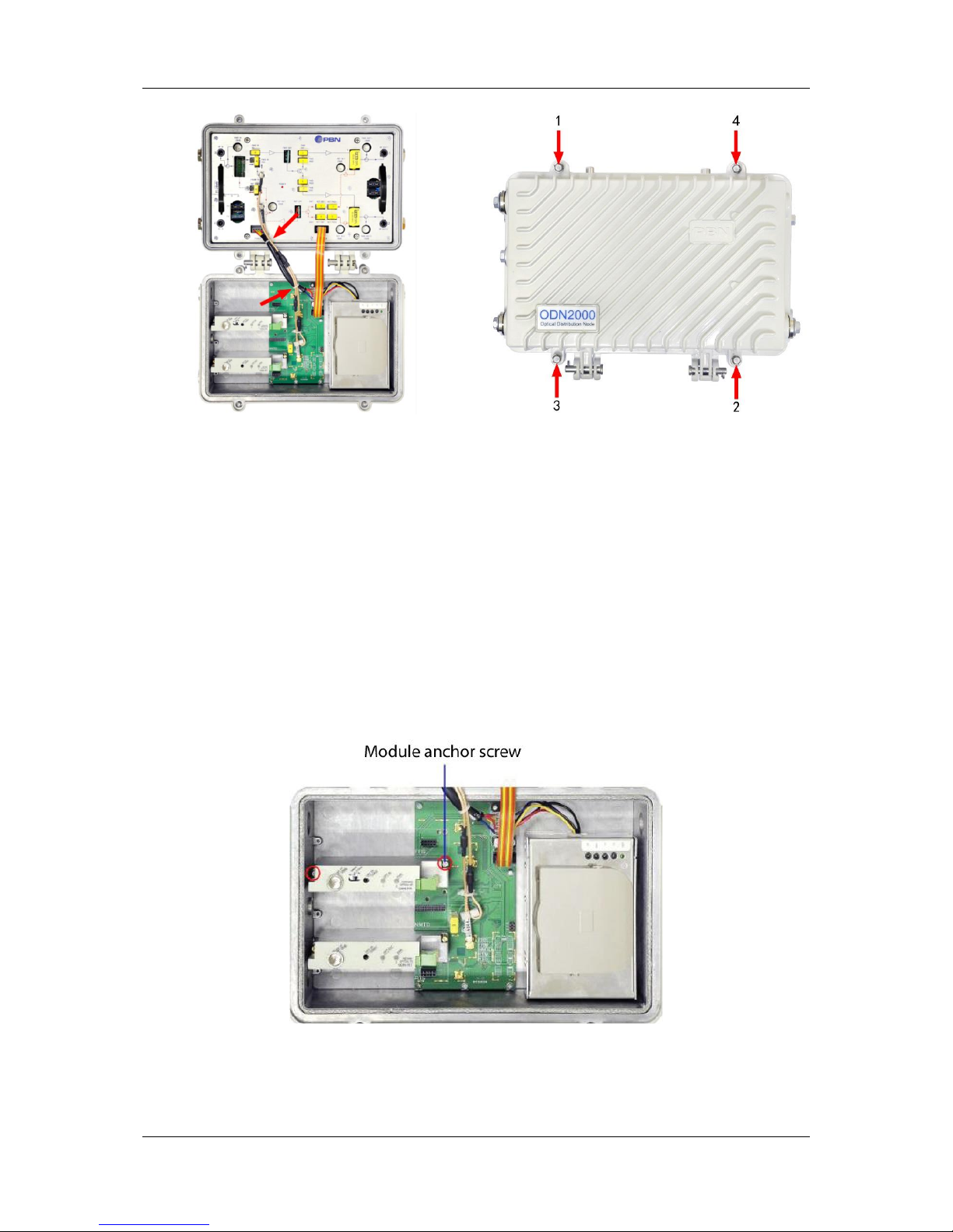
Where an ODN2000 plug-in module is used, spiral binding should be used to bind together the
power cable and the two RF cables (Figure 5-7) to reduce the possibility of them being caught
between the lid and base when closing.
Once all the above steps are completed, the node can be closed. When closing the node, tighten
the mounting screws in the order shown in Figure 5-8 (12341).
Note:
The IP67 rating of the ODN2000 is dependent on the proper sealing of all external node
interfaces. This includes the optical stub cable and all RF connectors.
Figure 5-6 ODN2000 Node Casing
Page 32
ODN2000/LE2000 User Manual
Pacific Broadband Networks Page 32 of 36
Figure 5-7 Internal Cabling Secured with
Cable Ties
Figure 5-8 Screw Tightening Order
5.4 Module Installation & Removal
The ODN2000 modules plug into the backplane of the node’s circuit board. To avoid causing any
damage, be careful with the pins located underneath each module during its insertion or removal.
5.4.1 Module Removal
Use the following procedure to remove an ODN2000 module during maintenance or replacement:
a) Disconnect all cables and wires.
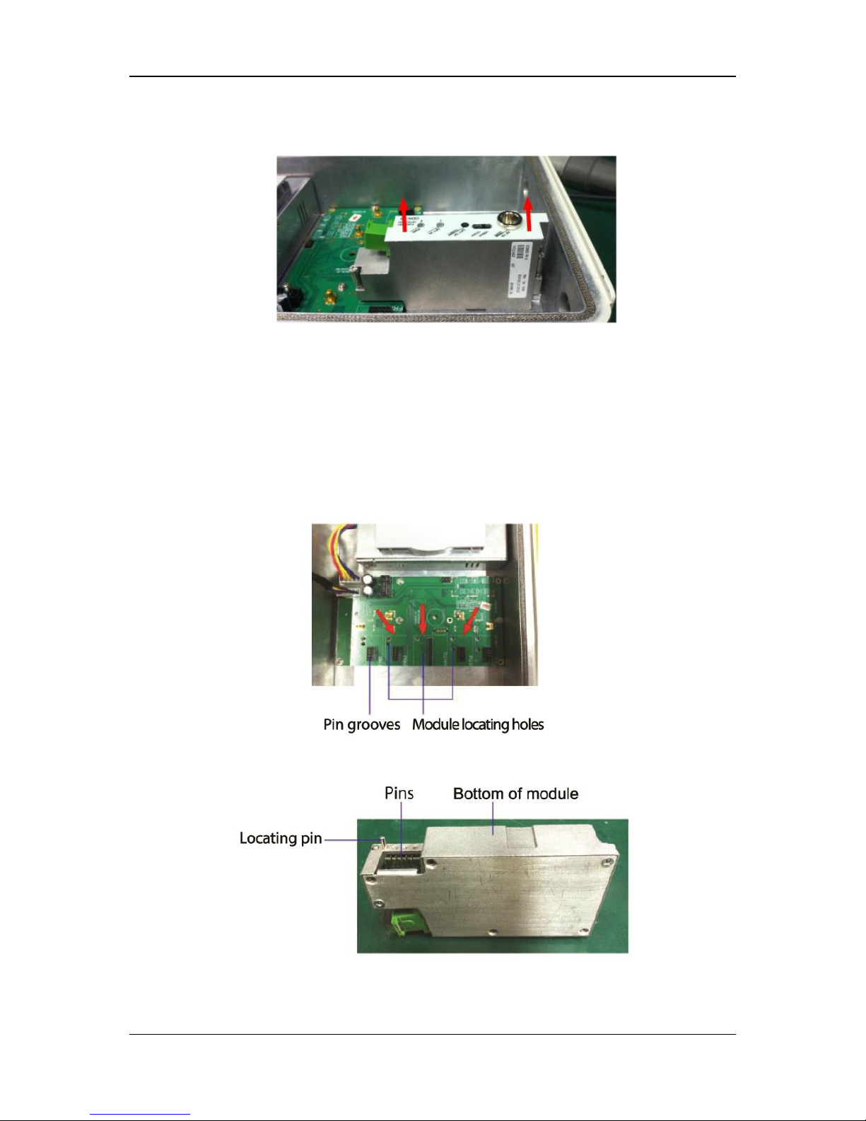
b) Unscrew the two anchor screws that hold the ODN2000 module in place (Figure 5-9).
Figure 5-9 Module Anchor Screws
Page 33
ODN2000/LE2000 User Manual
Pacific Broadband Networks Page 33 of 36
c) Vertically, lift the module firmly. Refrain from using excessive force. The module should
be lifted out at ease.
Figure 5-10 Module Removal
5.4.2 Module Insertion
Use the following procedure to install an ODN2000 module during maintenance or replacement:
a) On the backplane of the circuit board in the ODN2000 node’s module compartment,
locate the white rectangles (pointed to with red arrows in Figure 5-12). The module
should be installed into the slot specifically designed for it.
Figure 5-11 Backplane
Figure 5-12 Module Locating & Contact Pins
Page 34
ODN2000/LE2000 User Manual
Pacific Broadband Networks Page 34 of 36
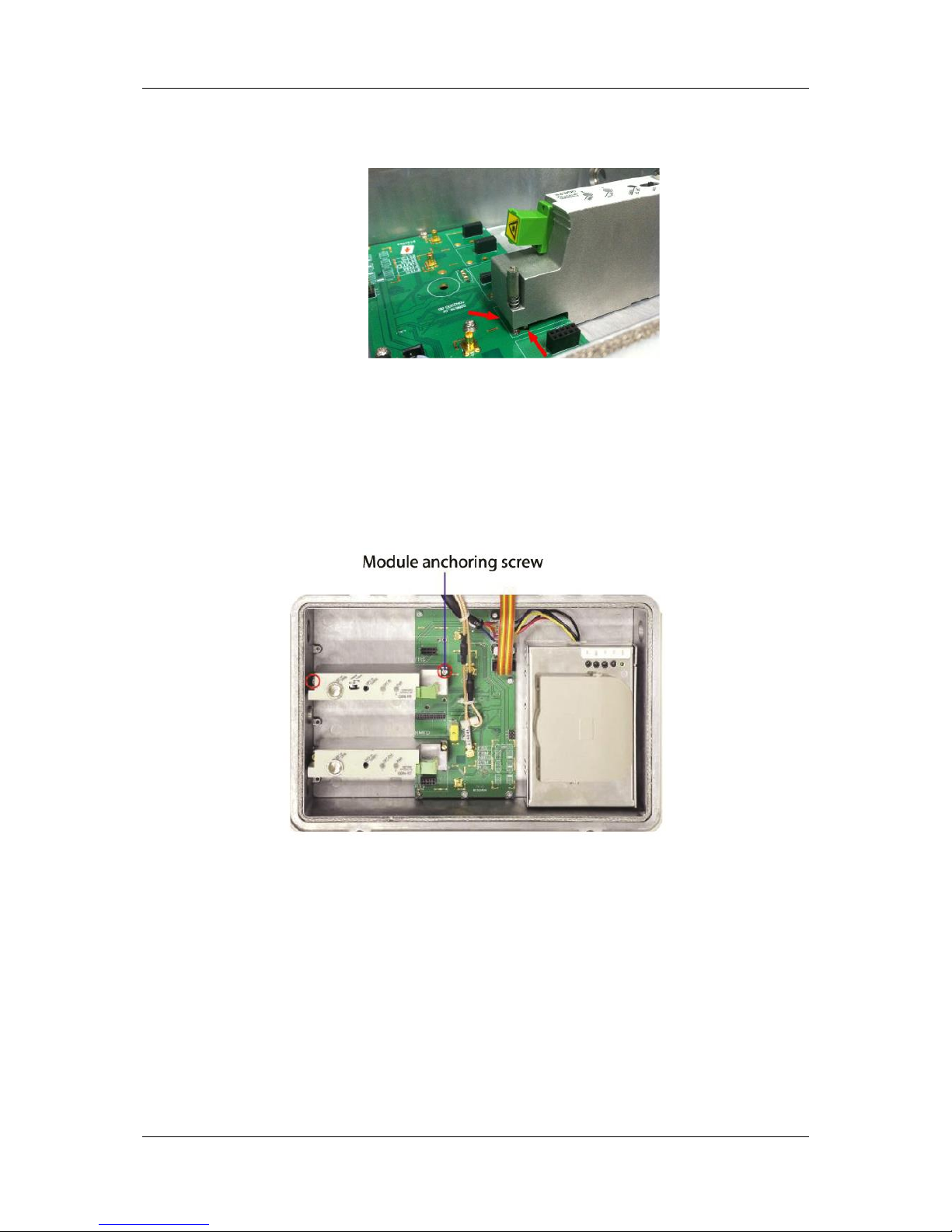
b) Align the sides of the modules and the edges of the white rectangles on the backplane,
locating pins and respective holes, contact pins and respective pin grooves.
Figure 5-13 Aligning the Module
c) The pins should not be obstructed by cables or wires (specifically, the ODN-RT RF port
test point cable).
d) Gently push down on the area of the module directly above the pins. The module should
slip into place with ease. Refrain from using excessive force.
e) Screw in the two anchoring screws.
Figure 5-14 Two Anchoring Screws
Page 35

ODN2000/LE2000 User Manual
Pacific Broadband Networks Page 35 of 36
6 Product Warranty
Pacific Broadband Networks warrants the ODN2000 and LE2000 for a period of one year from the
date of shipment. The liability of Pacific Broadband Networks under this warranty is solely limited
to repair and replacement.
Pacific Broadband Networks is not liable for DFB Laser failure after 90 days from receipt of item.
Any claim for DFB Lasers will be presented to the laser vendor for replacement. Pacific Broadband
Networks will make every effort to replace faulty lasers, although the ultimate judgment is at the
laser vendor’s discretion.
Repairs referred to Pacific Broadband Networks' qualified service personnel must meet the
following conditions:
1. The warranty registration has been completed and received by Pacific Broadband
Networks.
2. PBN’s helpdesk is promptly notified in writing or by telephone that a failure has occurred
or a defect was found.
3. PBN has determined that the equipment was not abused, misused, or operated under
conditions outside manufacturer’s specifications.
4. When returning a product, the return authorization number obtained from PBN must be
clearly marked on the product or the outside of the shipping container and the package
must include all relevant documents.
5. The customer is responsible for all shipping and handling charges. C.O.D. and freight
collect will not be accepted without prior approval from PBN.
The warranty does not cover the following:
1. Products purchased from someone other than PBN or an authorized PBN dealer.
2. Damage caused by accident, negligence, misuse, abuse, improper operation, or failure
to operate the equipment within the manufacturer’s specifications.
3. Damage caused by fluctuation in electrical current, lightning, power surges, etc.
4. Damage resulting from an overhaul, repair, or attempt to repair caused by someone other
than PBN’s qualified service personnel.
5. Any product for which the serial number has been defaced, modified, or removed.
6. Any product that has been opened or modified without prior written permission from PBN.
7. Replacement of parts necessitated by normal wear and tear.
8. Any consequential or implied damages.
Page 36

Offices:
Australia, Melbourne: Tel. +61-3-8561-1400
China, Beijing: Tel. +86-10-5791-0655
Americas: Tel. +1-888-339-8805
EMEA, Netherlands: Tel. +31-36-536-8011
Email: [email protected]
Website: www.pbnglobal.com
©2016 Pacific Broadband Networks. All rights reserved.
 Loading...