

PBN AIMA-FT5S Product User Manual
Offices
Australia, Melbourne : tel. +61-3-8561-1400
China, Beijing : tel. +86-10-5791-0655
Americas : tel. +1-888-339-8805
Australia, Melbourne : tel. +61-3-8561-1400
EMEA, Netherlands : tel. +31-36-536-8011
info@pbnglobal.com
www.pbnglobal.com
© 2014 Pacific Broadband Networks. All rights reserved.
AIMA-FT5S
1550 nm Optical Forward Transmitter - Standard
Product User Manual

AIMA-FT5S Product User Manual
Pacific Broadband Networks 18 July 2014 Page 2 of 62
AIMA FT5S
1550 nm Optical Forward Transmitter -Standard
Product User Manual
Last update
18 July 2014
Document version
0q
Document reference
FT5S Manual
Document status
Released
Prepared by
Pacific Broadband Networks
Prepared for
Product Users

AIMA-FT5S Product User Manual
Pacific Broadband Networks 18 July 2014 Page 3 of 62
Contents
1 About This Manual ............................................................................................................... 6
1.1 Related Documentation ....................................................................................................... 6
1.2 Document Conventions ....................................................................................................... 6
1.3 Technical Support ................................................................................................................ 7
2 Precautions .......................................................................................................................... 8
3 Overview .............................................................................................................................. 9
3.1 Product Description ............................................................................................................. 9
3.2 Product Key Features ........................................................................................................ 10
3.3 Specifications ..................................................................................................................... 11
3.4 Block Diagram.................................................................................................................... 13
3.5 Order Details ...................................................................................................................... 14
4 Module Characteristics ...................................................................................................... 15
4.1 Module Appearance and Port Layout ................................................................................ 15
4.1.1 Overview ............................................................................................................................ 15
4.1.2 Front Panel Layout ............................................................................................................ 16
4.1.3 Rear Panel Layout ............................................................................................................. 18
5 Installation .......................................................................................................................... 19
5.1 Preparatory Work for Installation ....................................................................................... 19
5.2 Unpacking .......................................................................................................................... 19
5.3 Module Installation ............................................................................................................. 20
5.4 Connecting Optical Cables ................................................................................................ 21
5.4.1 Using the Sliding Fiber Guide ............................................................................................ 21
5.4.2 Using the Fiber Tray .......................................................................................................... 23
5.4.3 Cleaning the Fiber Connector Ends and Front-panel Optical Ports .................................. 25
5.4.4 Connecting the Optical Fibers ........................................................................................... 26
5.5 Check Module LEDs .......................................................................................................... 26
5.6 Test the RF Input Signal .................................................................................................... 26
5.7 Test the Optical Output Signal ........................................................................................... 27
5.8 Initial Setup ........................................................................................................................ 28

AIMA-FT5S Product User Manual
Pacific Broadband Networks 18 July 2014 Page 4 of 62
6 Module Configuration & Alarm setup ................................................................................. 30
6.1 Port Configuration screen .................................................................................................. 30
6.1.1 Determine the RF power to the RF input port. .................................................................. 32
6.2 Applying RF settings to FT5S transmitter MGC mode ...................................................... 35
6.2.1 Sample RF load 80 channels analog RF load ................................................................... 35
6.2.2 Sample RF load for 42 analog channels analog of RF load .............................................. 36
6.2.3 Sample RF load of 50 analog channels+13 QAM64 channels and 15 QAM256 channels36
6.3 Applying RF settings to FT5S transmitter AGC mode ....................................................... 37
6.3.1 Sample RF load for 80 analog channels of RF load.......................................................... 37
6.3.2 Sample RF load for 42 analog channels of RF load.......................................................... 37
6.3.3 Sample RF load for 50 analog channels+13 QAM64 channels and 15 QAM256 channels
38
6.3.4 Confirming Input Signal ..................................................................................................... 40
6.3.5 Configuration of Module RF Signal.................................................................................... 41
6.4 Setup using separate BC and NC RF input in MGC mode ............................................... 42
6.4.1 RF transmitter setup using both BC and NC RF input ...................................................... 42
6.5 Setup using separate BC and NC RF input in AGC mode ................................................ 43
6.5.1 RF transmitter setup using both BC and NC RF input ...................................................... 44
6.6 Alarms Monitoring .............................................................................................................. 45
6.6.1 Alarm Status Pages ........................................................................................................... 45
6.6.2 Module operating voltage and temperature alarm ............................................................. 46
6.6.3 Module Port Alarms ........................................................................................................... 47
6.6.4 Alarm Monitoring Configuration ......................................................................................... 48
6.6.5 Input / Output Status Monitoring ........................................................................................ 50
6.7 Logs Management ............................................................................................................. 52
6.8 Device Upgrade ................................................................................................................. 53
6.9 Restoring Factory Defaults ................................................................................................ 54
6.10 Reboot ............................................................................................................................... 56
7 Troubleshooting ................................................................................................................. 57
8 Product Warranty ............................................................................................................... 58
9 Declaration of Conformity .................................................................................................. 59

AIMA-FT5S Product User Manual
Pacific Broadband Networks 18 July 2014 Page 5 of 62
Appendix A: Default Alarm Limit Settings ........................................................................................ 60
Appendix B: Factory Default Settings ............................................................................................... 61

AIMA-FT5S Product User Manual
Pacific Broadband Networks 18 July 2014 Page 6 of 62
1 About This Manual
1.1 Related Documentation
The following documents may be used in conjunction with this manual:
PBN.AIMA3000 - Product User Manual
PBN.AIMA ASMM - Product User Manual
AIMA3000 NMS Web Management System Product User Manual
- PBN.NMS3-EPSM - Basic Inventory Management
- PBN.NMS3-EPSM - Basic Alarm Management
- PBN.NMS3-EPSM - Basic System Management
- PBN.NMS3-EPSM - Basic Template Management
The document can be found at the download section of PBN’s corporate website:
http://www.pbnglobal.com/en/support/downloads/manuals. A registered account is required.
1.2 Document Conventions
Before you use the manual, please familiarize yourself with the format used in this manual.
‘*’ Asterisk: Points marked with an asterisk means there is a corresponding note on the page

AIMA-FT5S Product User Manual
Pacific Broadband Networks 18 July 2014 Page 7 of 62
1.3 Technical Support
If you need help in the process of setting up and maintaining an FT5S, please contact PBN's technical
support staff:
Australia:
Suite 15, Building 3, 195 Wellington Road
Clayton, VIC 3168, Australia
Phone: +61-3-8561-1400
Fax: +61-3-9562-2957
Europe:
Transistorstraat 46-II, 1322 CG Almere
The Netherlands
Phone: +31-36-536-8011
Fax: +31-36-536-4367
China:
Unit 403, Entrance C, Building No. 201 A-10, Jiuxianqiao Beilu,
Chaoyang District, Beijing, China
Phone: +86-10-5791-0655
Fax: +8610-5791-0855
Americas:
Phone: +1-888-339-8805
Company Website: www.pbnglobal.com
Support Email: support@pbnglobal.com
AIMA-FT5S Product User Manual
Pacific Broadband Networks 18 July 2014 Page 8 of 62
2 Precautions
WARNING!
This equipment is intended for indoor applications. To prevent fire or
electrical shock, or damage to the equipment, do not expose units to
water or moisture.
You should carefully read and thoroughly understand the contents of the manual before
installing and using this equipment.
A typical connector is the SC/APC 8°. Note: An 8 ° angle polished optical connectors must be
used.
At any time, there may be dangerous voltage inside the device.
Do not power up before the cover and the panels of the equipment are installed and the
enclosure is closed.
Cleaning
Only use a damp cloth for cleaning the front panel. Use a soft dry cloth to clean the top of the unit. Do
not use any spray cleaners or chemicals of any kind.
Outage or overload requiring service and repairs
Unplug the unit and refer the servicing to Pacific Broadband Networks’ qualified service personnel
only.
Servicing and repairs
Do not attempt to service this unit yourself. Refer all servicing needs to Pacific Broadband Networks’
qualified service personnel only.
WARNING!
Exposure to class 3A laser radiation is possible. Access should be
restricted to trained personnel only. Do not view exposed fiber or
connector ends when handling optical equipment.

AIMA-FT5S Product User Manual
Pacific Broadband Networks 18 July 2014 Page 9 of 62
3 Overview
3.1 Product Description
The 1550 nm Forward Transmitter Module - Standard series (FT5S) is designed to plug into PBN’s
latest Advanced Intelligent Multi-services Access platform - the AIMA3000.
PBN’s AIMA3000 FT5S is available in single and dual laser configurations. It features advanced
forward transmitters engineered for multi-service operators (MSOs) to increase network capacity to
satisfy an ever-growing subscriber demands for more bandwidth. The module’s operating wavelength
conforms to ITU’s standards and works with PBN’s Erbium Doped Fiber Amplifier Module (EDFA). It
allows for full-spectrum broadcast and narrowcast channels, providing the utmost flexibility for MSOs
during the transition to all digital.
The FT5S series employs an advanced RF circuit design and laser with high-quality and low-chirp
characteristics. The module offers a consistent optical modulation index (OMI) and ensures high-index
optical power output. In addition, it is a cutting-edge optoelectronic design for the delivery of highquality transmissions, in both analog and digital formats over passive fiber optical networks.
All FT5S models can also be conveniently monitored and controlled through a computer connected to
one of the Ethernet ports or an Android mobile device via the ASMM module. All module settings are
retained in non-volatile memory to ensure trouble-free operation. Bulk updating, automatic uploading
and downloading of configuration files can be done when using PBN’s NMSE web-based
management system.

AIMA-FT5S Product User Manual
Pacific Broadband Networks 18 July 2014 Page 10 of 62
3.2 Product Key Features
Plug-and-play with the AIMA3000 platform
High quality 1550 nm, isolated low-chirp analog DFB laser
RF amplifier gain blocks with advanced GaAs technology for better performance
Conforms to the ITU DWDM standards
Frequency response from 45 MHz to 1000 MHz fit for both broadcast and narrowcast
applications
Alarm monitoring via ASMM web interface and PBN NMSE
Automatic gain control (AGC) for a consistent optical modulation index (OMI)
Automatic thermo-cooler control (ATC) for a consistent laser temperature
Automatic power control (APC) for a consistent optical output power
Available in single or dual transmitter configurations
Up to 32 transmitters per chassis
Remote firmware upgrade and auto upload/download of configuration files through ASMM
web interface or using PBN’s NMSE
Bulk firmware updates through PBN’s NMSE
FCC, CE and RCM
(1)
compliant
(1)
See Declaration of Conformity for current status.

AIMA-FT5S Product User Manual
Pacific Broadband Networks 18 July 2014 Page 11 of 62
3.3 Specifications
Optical Performance
Optical wavelength
1550 ±5 nm or ITU wavelength
Optical outputs
Single port: 1
Double port: 2
Output power
8 dBm, 9 dBm, 10 dBm
Optical return loss
> 60 dB
Optical connector
SC/APC
(1),
LC/APC, FC/APC, E2000 / APC
Laser RIN
<- 155 dB/Hz
RF Performance
RF bandwidth
45 ~ 1000 MHz
RF flatness
± 0.75 dB
RF input return loss
> 16 dB
RF input level,
NC nominal
(2)
15 ~ 25 dBmV per channel
RF input level,
BC nominal
(2)
10 ~ 25 dBmV per channel
AGC range
±3 dB
RF impedance
75 Ω
RF test point relative to RF
input port
-20 ±1 dB
Alarms and laser status
Front-panel LEDs, SNMP traps
RF input connectors
Single port: 2 x GSK-type female (1 for NC input, 1 for BC input)
Double port: 4 x GSK-type female (2 for NC input, 2 for BC
input)
RF test points
Single port: 3 x Mini-SMB
(3)
Double port: 4 x Mini-SMB
(4)
Notes:
(1) Standard option. Contact a PBN Sales Representative for availability of other options.
(2) dBuV=60+dBmV.
(3) Three mini-SMBs on front panel: one each for BC and NC inputs and one for laser RF level.
(4) Four mini-SMB connectors on front panel: BC and NC inputs test ports (user switchable) and two for laser RF level.

AIMA-FT5S Product User Manual
Pacific Broadband Networks 18 July 2014 Page 12 of 62
Link Performance
(5)
CNR (4 MHz narrow bandwidth)
> 53 dB
CSO > 58 dB
CTB > 67 dB
MER
> 38 dB
BER
< 1E-9
General
Power supply
Powered via AIMA3000 backplane
Power consumption
Single port: < 8 W
Double port: < 15 W
Operating temperature
-5 ~ +55 oC
Operating humidity
90 % (Non-condensing)
Storage temperature
-25 ~ +70 oC
Storage humidity
90 % (Non-condensing)
Dimensions (W*D*H)
24.6 * 410 * 152.5 mm
Weight
0.88 kg
Supported network
management options
PBN’s NMSE or through ASMM’s Web Interface
Notes:
(5) CNR, CSO, CTB and MER are loaded with 30 NTSC+124 QAM256 or 30 PAL D/K+85 QAM256. BER is loaded with 30
NTSC+124 QAM256, 30 PAL D/K+85 QAM256 or 153 QAM256. All are measured with PBN referenced optical receiver with
5 km single-mode optical fiber 0 dBm.
AIMA-FT5S Product User Manual
Pacific Broadband Networks 18 July 2014 Page 13 of 62
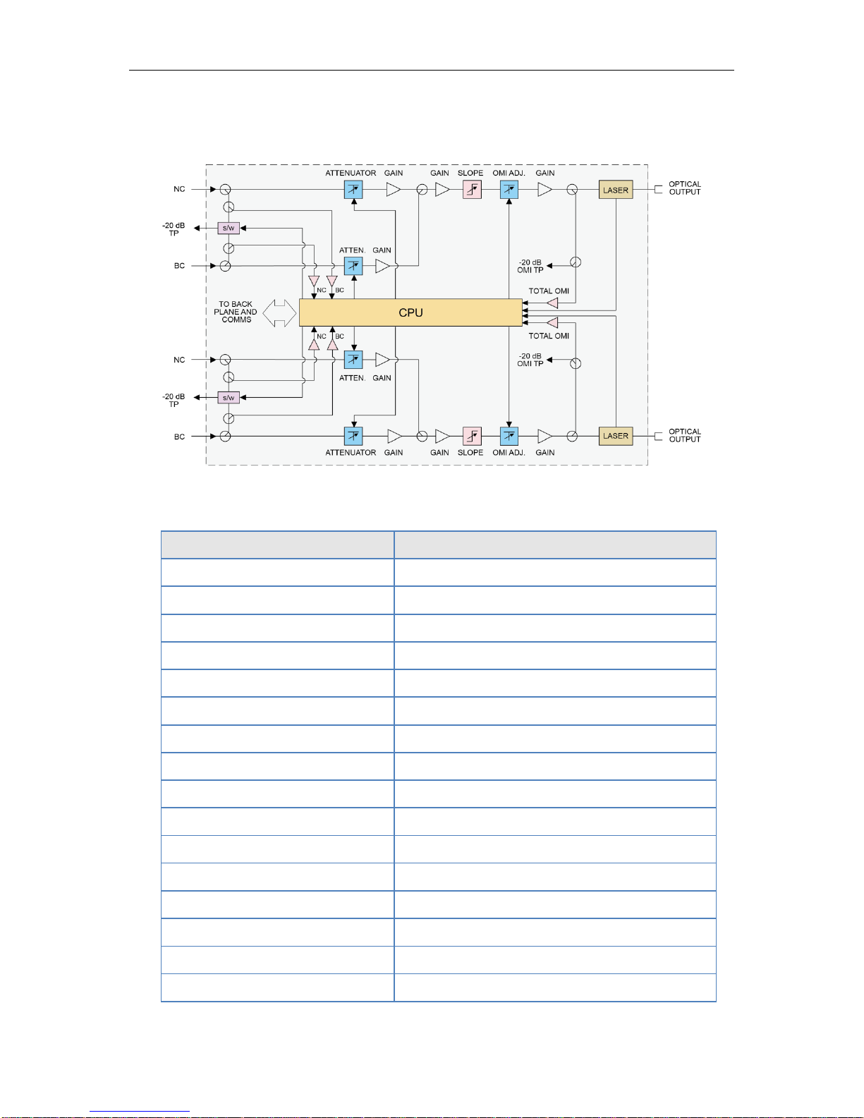
3.4 Block Diagram
Figure 3-1 Block diagram FT5S
Table 3-3 FT5S Block Diagram Glossary
Parameters
Glossary
NC
Narrowcast Input
NC MGC
Narrowcast Input Gain
-20 dB TP
-20 dB Test Point
BC
Broadcast Input
BC MGC
Broadcast Input Gain
PRE AMPLIFIER
Pre-Amplifier Module
MID AMPLIFIER
Mid-Amplifier Module
OMI AGC
OMI Automatic Gain Control
OUTPUT STAGE
Output Stage Amplifier Module
LASER
Laser
OPTICAL OUTPUT
Optical Output
TO BACK PLANE AND COMMS
Data Bus
NC1
Narrowcast Input Internal Test Point
BC1
Broadcast Input Internal Test Point
TOTAL OMI
Total Modulation (OMI) at laser
CPU
Central Processing Unit

AIMA-FT5S Product User Manual
Pacific Broadband Networks 18 July 2014 Page 14 of 62
3.5 Order Details
A-FT5S-[V]-[W]-[X1X2]-[Y]-[Z] 1550 nm Forward Transmitter – Standard
Options:
V Number of Optical Ports
S Single (1)
D Dual (2)
W Optical Output Power
08 8 dBm (6.3 mW) optical power
09 9 dBm (8 mW) optical power
10 10 dBm (10 mW) optical power
X1X
2
(1)(2)
First Channel Last Channel
21 192.1 THz (1560.61 nm)
23 192.3 THz (1558.98 nm)
25 192.5 THz (1557.36 nm)
27 192.7 THz (1555.75 nm)
29 192.9 THz (1554.13 nm)
31 193.1 THz (1552.52 nm)
33 193.3 THz (1550.92 nm)
35 193.5 THz (1549.32 nm)
… …
51 195.1 THz (1536.61 nm)
Y Optical Connector Type
S SC/APC
(3)
L LC/APC
F FC/APC
E E2000/APC
Z Bandwidth
1G 45 ~ 1000 Hz
Notes:
(1) Default spacing is 200 GHz. For other wavelength configurations not listed, please contact PBN.
(2) X2 used only in dual transmitter version
Dual version, X1 is first channel and X2 is second channel
Examples:
Single
X1
25
Dual
X1X2
2527
(3) Contact PBN Representatives for detailed optical channel information.
AIMA-FT5S Product User Manual
Pacific Broadband Networks 18 July 2014 Page 15 of 62
4 Module Characteristics
4.1 Module Appearance and Port Layout
4.1.1 Overview
Figure 4-1 Module Appearance
AIMA-FT5S Product User Manual
Pacific Broadband Networks 18 July 2014 Page 16 of 62
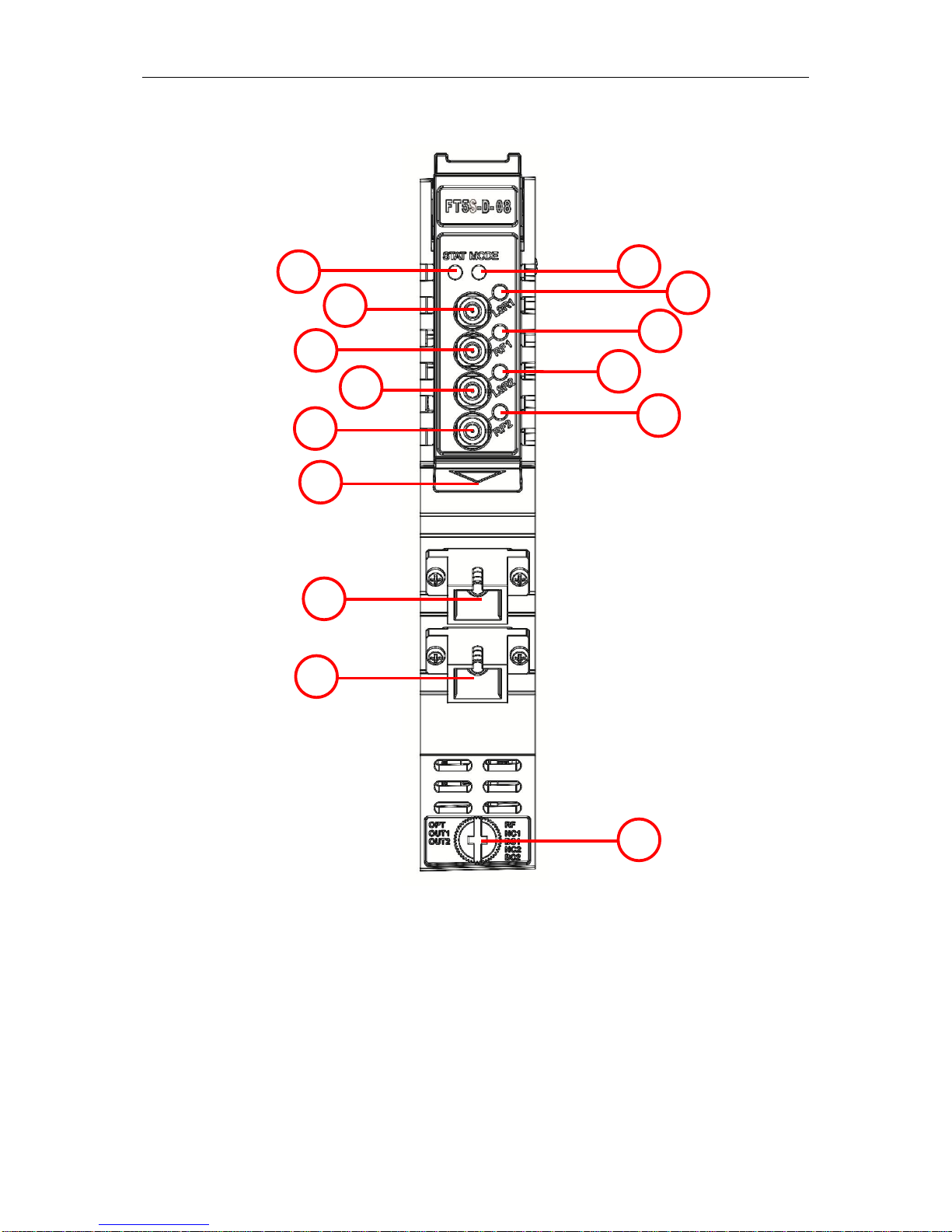
4.1.2 Front Panel Layout
Figure 4-2 FT5S Front Panel Layout
1
2
3
6
5
9
10
12
14
11
13
4
7
8

AIMA-FT5S Product User Manual
Pacific Broadband Networks 18 July 2014 Page 17 of 62
Table 4-1 FT5S Front Panel Functions
Item Number
Item
Description
1
MODE LED
Module Gain Control Mode Indicator
MGC: Green Light Blinking
AGC: Green
2
STATUS LED
Module Alarm Indicator
Normal: Green
Minor Alarm: Orange
Major Alarm: Red
3
LSR1 LED
Laser Status Indicator
ON: Green
OFF: Green Light Blinking
Major Alarm: Red
4
LSR1-OUT
Laser 1 Input Test Point
5
RF1 LED
RF1 Status Indicator
ON: Green
Output RF level slightly high/Low: Orange
Output RF level too high/low: Red
6
RF1-OUT
RF1 Test Point
7
LSR2 LED
Laser Status Indicator
ON: Green
OFF: Green Light Blinking
Major Alarm: Red
8
LSR2-OUT
Laser 2 level input test point
9
RF2 LED
RF2 Status Indicator
ON: Green
Output RF level slightly high/Low: Orange
Output RF level too high/low: Red
10
RF2-OUT
RF2 Test Point
11
Orange tab-retaining
clip
Used to plug and anchor the module
The tab-retaining clip will pop-up after pressing
the release and plug module.
12
OPT OUT 1
Optical output 1
13
OPT OUT 2
Optical output 2
14
Mounting Screw
Module fastening screw
CAUTION!
“OPT OUT” emits a non-visible laser radiation when working.
AIMA-FT5S Product User Manual
Pacific Broadband Networks 18 July 2014 Page 18 of 62
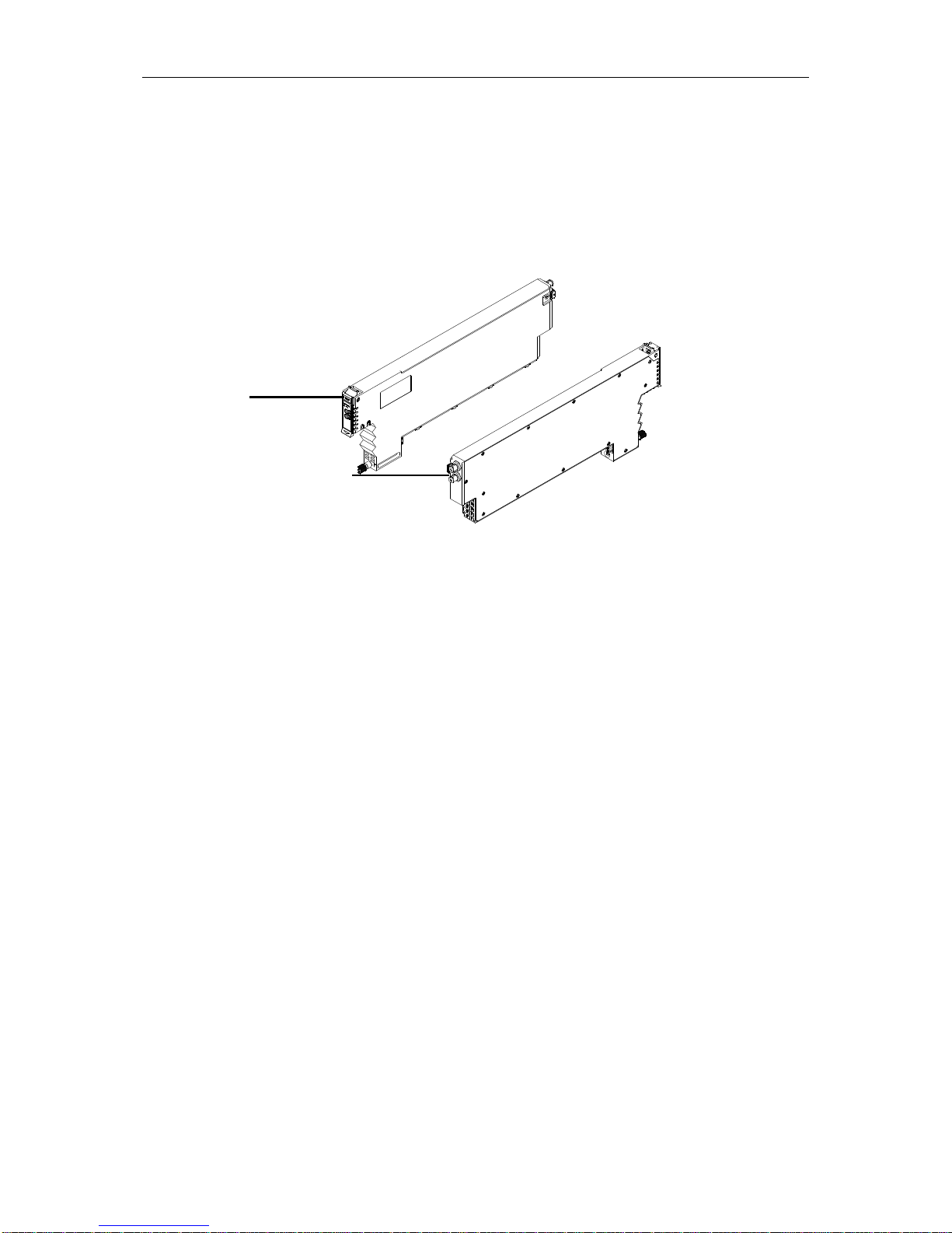
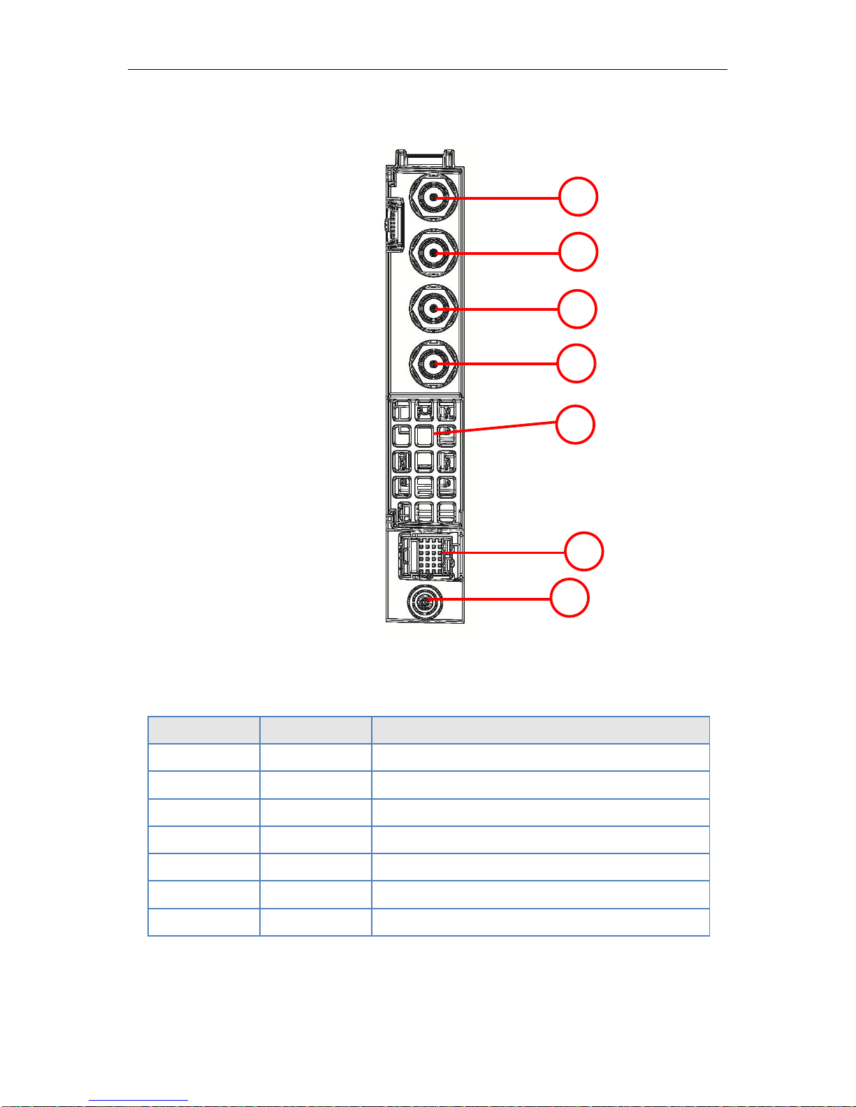
4.1.3 Rear Panel Layout
Figure 4-3 Rear Panel Layout
Table 4-2 FT5S Rear Panel Functions
Serial Number
Item
Description
1
NC1 IN
Narrowcast RF 1 Input
2
BC1 IN
Broadcast RF 1 Input
3
NC2 IN
Narrowcast RF 2 Input
4
BC2 IN
Broadcast RF 2 Input
5
Air Vent
Air vent allowing air to flow out of the module
6
Bus Connector
Power and communication port
7
Placement Pin
Used to position the module in the chassis
1
2
3
5
6
4
7

AIMA-FT5S Product User Manual
Pacific Broadband Networks 18 July 2014 Page 19 of 62
5 Installation
5.1 Preparatory Work for Installation
Before installing this device, you must ensure that the unit is intact and ready for installation.
Unpack and check the unit: Open the box to check for any damage that may have occurred during
shipment.
If damage is found, please contact a PBN customer support representative.
Necessary equipment and tools for installation:
Table 5-1 Necessary equipment and tools for installation
Tools/Modules
Description
Phillips screwdriver PH1/PH2
For fastening the FT5S module in the AIMA3000
chassis
FT5S Module
The module to install into the AIMA3000 chassis
5.2 Unpacking
Unpack the module. Keep the packaging materials for future transport needs.
Check the package manifest, record the product module type, serial number, purchase date, and any
other relevant information to facilitate later management and maintenance.
Table 5-2 Packing Manifest
No.
Description
Qty
1
FT5S module
1 2 Product User Manual (CD)
1
3
Individual test sheet (Certificate of
Performance)
1
 Loading...