

http://www.pbi-china.com
Twin IP to Analog Trans-modulator
User Manual

Contents
Notices ....................................................................................................................... 1
1 Overview ................................................................................................................. 4
2 Features.................................................................................................................. 4
3 Technical Specifications ......................................................................................... 4
4 Order Information .................................................................................................... 6
5 Front panel and rear panel instructions .................................................................. 6
5.1 Front panel ................................................................................................... 6
5.2 Rear panel .................................................................................................... 7
6 Menu Operating Instructions Via DMM-1000CU ..................................................... 8
6.1 Status ........................................................................................................... 9
6.2 Config ........................................................................................................... 9
6.3 Network ...................................................................................................... 11
6.4 System ........................................................................................................ 11
7 Web Control .......................................................................................................... 12
7.1 Status Page ................................................................................................ 12
7.2 Input Setting Page ...................................................................................... 13
7.3 RF Page ..................................................................................................... 14
7.4 Decoder-1/2 Page....................................................................................... 15
7.5 System Page .............................................................................................. 17
8 Installation ............................................................................................................. 20
9 Accessories .......................................................................................................... 20
1701IM
- 1 -
Notices
COPYRIGHT (Copyright © 2012 Beijing Jaeger Communication Electronic Technology Co., Ltd.)
Not to be copied, used or translated in part or whole without Beijing Jaeger prior consent in writing
except approval of ownership of copyright and copyright law.
WARRANTY
This warranty does not cover parts which may become defective due to misuse of the information
contained in this manual.
Read this manual carefully and make sure you understand the instructions provided. For your safety,
be aware of the following precautions.
WARNING! IMPORTATNT SAFETY INSTRUCTIONS
CAUTION: TO REDUCE THE RISK OF ELECTRIC SHOCK, DO NOT REMOVE
COVER (OR BACK). NO USER SERVICEABLE PARTS INSIDE. REFER
SERVICING TO QUALIFIED SERVICE PERSONNEL.
WARNING
• To reduce the risk of fire or electric shock, do not expose this apparatus to rain or moisture.
• To avoid explosion danger, do not dispose of batteries in an open fire.
CE MARK FOR EUROPEAN HARMONISED STANDARDS
The CE mark which is attached to these products means it conforms to EMC
Directive (89/336/EEC) and Low Voltage Directive (73/23/EEC).
IMPORTANT INFORMATION
Please retain the original packaging, should it be necessary at some stage to return the unit.
Disposal of Old Electrical and Electronic Equipment (Applicable in the European Union and
other European countries with separate collection systems)
This symbol on the product or on its packaging indicates that this product shall not
be treated as household waste. Instead it shall be handed over to the applicable
collection point for the recycling of electrical and electronic equipment. By
ensuring this product is disposed of correctly, you will help prevent potential
negative consequences for the environment and human health, which could
otherwise be caused by inappropriate waste handling of this product. The
recycling of materials will help to conserve natural resources. For more detailed
information about recycling of this product, please contact your local Civic Office,
your household waste disposal service, or the shop where you purchased the
product.
COPYRIGHTS
Television programs, movies, video tapes, discs, and other materials may be copyrighted.
Unauthorized recording of copyrighted material may be against the copyright laws in your region.
Also, use of this product with cable television transmissions may require authorization from the cable
television operator or transmitter/owner.
VENTILATION
• Do not expose the product to high temperatures, such as placing it on top of other product that
produce heat or in places exposed to direct sunlight or spot lights.
• The ventilation slots on top of the product must be left uncovered to allow proper airflow into the
unit.
• Do not stand the product on soft furnishings or carpets.
• Do not stack electronic equipment on top of the product.
• Do not place the product in a location subject to extreme changes in temperature. The
temperature gradient should be less than 10 degrees C/hour.
• Place the product in a location with adequate ventilation to prevent the build-up of heat inside the
product. The minimum ventilation space around the unit should be 7 cm. The ventilation should
not be impeded by covering the ventilation openings with items, such as newspapers, table cloth,
curtains, etc.

1701IM
- 2 -
POWER SOURCES
• The product is not disconnected from the AC power source (mains) as long as it is connected to
the power outlet or wall socket, even if the product is turned off.
• If the product will not be used for a long period of time, disconnect it from the AC power outlet or
wall socket.

1701IM
- 3 -
Before Using the Device
Thank you for purchasing the DMM-1701IM twin IP to analog trans-modulator. This User Manual is
written for operators/users of the DMM-1701IM to assist in installation and operation. Please read
this user manual carefully before installation and use of the device.
FOR YOUR SAFETY
This equipment is provided with a protective earthing ground incorporated in the power cord. The
main plug shall only be inserted in a socket outlet provided with a protective earth contact. Any
interruption of the protective conductor, inside or outside the device, is likely to make the device
dangerous. Do not remove the covers of this equipment. Hazardous voltages are present within this
equipment and may be exposed if the covers are removed. Only Beijing Jaeger trained and approved
service engineers are permitted to service this equipment.
The supplied AC power cable must be used to power the device. If the power cord becomes
damaged it must be replaced. No operator serviceable parts inside. Refer servicing to Beijing Jaeger
trained and approved service engineers. For the correct and safe use of the device, it is essential
that both operating and servicing personnel follow generally accepted safety procedures in addition
to the safety precautions specified in this manual. Whenever it is likely that safety protection is
impaired, the device must be made in-operative and secured against unintended operation. The
appropriate servicing authority must be informed. For example, safety is likely to be impaired if the
device fails to perform the intended measurements or shows visible damage.
WARNINGS
• The mounting environment should be relatively dust free, free of excessive vibration and the
ambient temperature between 0C° to 40C°. Relative humidity of 20% to 80% (non-condensed) is
recommended.
• Avoid direct contact with water.
• Never place the equipment in direct sunlight.
• The outside of the equipment may be cleaned using a lightly dampened cloth. Do not use any
cleaning liquids containing alcohol, methylated spirit or ammonia etc.
• For continued protection against fire hazard, replace line fused only with same type.
• Air intake for cooling is achieved via holes at the side of the device and the fans inside. The air
flow should not be obstructed. Therefore, the device has to be placed on a flat surface, leaving
some space at the sides of the device.
• When in operation, the internal temperature should not exceed the limit of 70C°.
1701IM
- 4 -
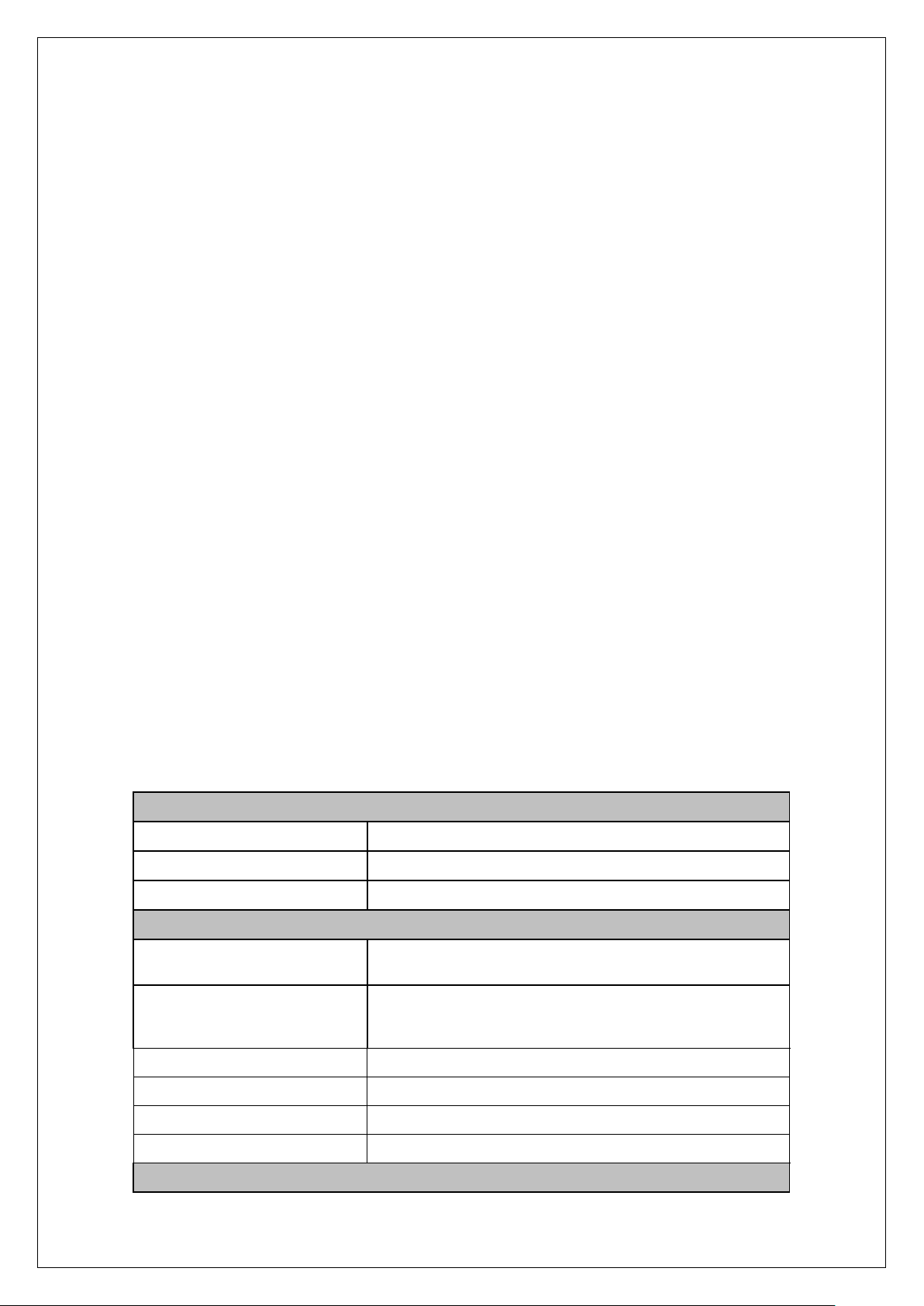
IP Input
Connector Type
2*RJ45 10/100 Base-T (TS/IP-2 share with Web control )
Standard
RTP/UDP(Uni/Multicast)
Effectual Output Bit Rate
70Mbps(max)
RF Output
Connector Type
1x F Type female, 75Ω(primary output)
1x F Type female, 75Ω(-20dB for monitoring)
Input Frequency Range
48MHz~860MHz, step by 10 KHz (two adjacent analog channels
output)
Video Output Level
100±3dBuV
Spurious Rejection
≥55dB
Output Return Loss
10dB
Output level Attenuation
0~18dB(adjustable)
Video Modulation
1. Overview
DMM-1701IM is a high performance twin IP to analog trans-modulator, it supports
MPEG-2\H.264 digital signal decoding with HD\SD definition. With 2 independent IP
interface, it can receive 2 IP multicast/unicast, and trans-modulate 2 programs by built-in
modulators, then outputs a combined signal via RF output port.
With its full compliance to analog standards including PAL, NTCS and SECAM,
DMM-1701IM is a better deployment for digital to analog system.
2. Features
◎Support MPEG-2/H.264 HD/SD TS decoding
◎Support various analog TV standards including PAL B/G, PAL D/K, SECAM B/G, SECAM D/K
and NTSC
◎Two IP multicast/unicast input ports
◎Support A2 stereo modulation(optional)
◎Two adjacent analog channels output in range of 48-860MHz
◎Out level 100dBuV per channel
◎Remote control and supervision by SNMP and HTTP web
◎Upgrade via FTP or USB.
◎Accommodated in 4RU 19” chassis (DMM-1000MF) which supports up to 8 modules and
equipped with auto-backup Power Supply module.
3. Technical Specifications
1701IM
- 5 -
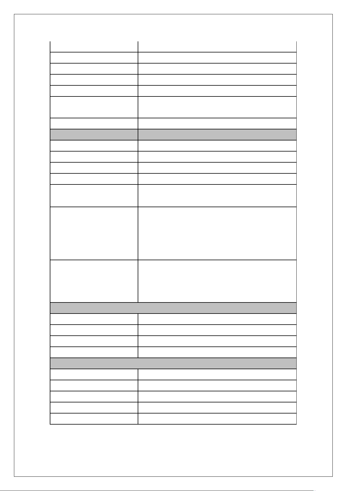
Video modulation depth
85%~87.5%
Video in-band flatness
≤2dB
Differential Gain
≤7%
Differential Phase
≤5°
Video SN Ratio
≥45dB
Chrominance/Brightness
Delay Differential
≤45nS
K2T
≤4%
Audio Modulation
Audio SN Ratio
≥55dB
Audio Pre-emphasis
50μs(B/G, D/K, I), 75μs (M/N)
Audio Frequency Response
±1.5dB (40Hz~15KHz)
Total Harmonic Distortion
≤1.2%
Audio Modulation Deviation
40 ~ 100KHz peak to peak(D/K,B/G,I)
50KHz peak to peak (M/N)
Audio Carrier Frequency(main)
6.5MHz ± 5KHz (D/K)
6.0MHz ± 5K (I)
5.5MHz ± 5KHz (B/G)
4.5MHz ± 5KHz (M/N)
Audio Carrier Frequency(second,
Only suitable to A2 Stereo
trans-modulator)
6.742MHz ± 5KHz (D/K)
6.258MHz ± 5KHz (D/K, Poland)
5.742MHz ± 5KHz (B/G)
64.742MHz ± 5KHz (M/N)
Control & Monitoring
Connector Type
1×RJ45, 10/100 Base-T, for Web Control
Remote Control
SNMP, HTTP(WEB interface)
Local Control
Handheld Programmer Unit
Software Upgrade
Quick upgrade via USB, or FTP loader
Physical parameter
Power supply
DC 3.3V/5V/12V, supplied by DMM-1000MF chassis
Power Consumption
30W (Max.)
Operating Temperature
0 ~ 45℃
Storage Temperature
-10 ~ 60℃
Humidity
10 ~ 90%, Non-condensed

1701IM
- 6 -
DMM-1701IM-xx series
IP Input type
Model
Video Audio
MONO
A2
PAL D/K
02
04
PAL D/K(Poland)
08
PAL B/G
12
14
NTSC
22
-
SECAM D/K
32
34
SECAM L
42
-
PAL-I
52
-
4. Order information
5. Front panel and rear panel instructions
5.1 Front panel

1701IM
- 7 -
A1 Control
TS/IP-2 TS over IP input interface, also used as Web control
A2 TS/IP-1 TS over IP input interface
A3 USB Used to upgrade software version of this device.
A4 Reset Used to reset the device’s settings.
A5 Power Power indicator, green light means power supply is working
well.
A6 Alarm Alarm indicator, green light means this device is working
well.
A9 Handset Used to connect DMM-1000CU handset unit for control.
5.2 Rear panel
B1 RF Out primary RF output port
B2 RF Monitor -20dB output port for monitoring

1701IM
- 8 -
Main Menu
Status
Network
System
IP Input Bitrate
Decoder-1
Decoder-2
RF Output Mode
USB
IP1
IP2
RF Frequency1
RF Frequency2
RF Level
RF Audio Mode-1
RF Audio Mode-2
RF Switch-2
RF Modulator Mode
USB Status
Service→Service Type
Service Name
Provider Name
Video→Video PID
Audio→Audio PID
Local Setting: IP Address
Network Mask
Gateway
Tarp IP: Tarp IP Address
HTTP Login: Username
Password
Version Info
Product Name→1701IM
Factory Setting
Debug Mode Setting
Force Upgrade
Config
Program
Video Output
Video Standard
Aspect Ratio
Subtitle priority
Subtitile Lang
Close Cuption
CVBS SUB
Audio Output
Audio Level
Audio Mode
Audio Priority
BISS
BISS Mode→
(Mode 0/1/E)
Decoder-1
Decoder-2
RF Setting
RF Frequency1
RF Frequency2
RF Level
RF Audio Mode-1
RF Audio Mode-2
RF Switch-2
Input Setting
Stream IP 1
Stream IP 2
Uni/Mul 1 Setting
Uni/Mul 2 Setting
6. Menu operating instructions via DMM-1000CU
Users are advised to restore factory setting of the machine before the first time using it.
Users are advised not to change those temporarily useless parameters in order to avoid
unnecessary fault.
After power on, the Local IP address will be shown on the LCD of DMM-1000CU. User can
press〔ENTER〕to get into the main menu.

1701IM
- 9 -
Status
IP1
IP2
RF Frequency1
RF Frequency2
RF Level
RF Audio Mode-1
RF Audio Mode-2
RF Switch-2
RF Modulator Mode
Service Service Type
Service Name
Provider Name
Video Video PID
Audio Audio PID
USB Status
IP Input Bitrate
RF Output Mode
Decoder-1
Decoder-2
USB
6.1 Status:
6.1.1 Input Bit Rate
1) IP1: If there is TS over IP input signal from IP port1, it will display the input bit rate.
2) IP1: If there is TS over IP input signal from IP port2, it will display the input bit rate.
6.1.2 RF Output Mode
1) RF Frequency1: Display the RF frequency for outputting modulated program1.
2) RF Frequency2: Display the RF frequency for outputting modulated program2.
3) RF Level: Display the RF level.
4) RF Audio Mode-1: Display the audio mode(MONO or A2) of modulated program1.
5) RF Audio Mode-2: Display the audio mode(MONO or A2) of modulated program2.
6) RF Swich-2: Display if the RF function for program2 is enabled or disabled.
7) RF Modulation Mode: Display the analog format of programs outputted from RF.
6.1.3 Decoder-1/2
1) Service: Display some information of decoded program such as Service Type, Service
Name, Provider Name.
2) Video: Display the video PID of decoded program.
3) Audio: Display the audio PID of decoded program.
6.1.4 USB
USB: If there is a USB device plugging, it will display the device information.
6.2 Config

1701IM
- 10 -
Config
Program
Video Output
Video Standard
Aspect Ratio
Subtitle priority
Subtitile Lang
Close Cuption
CVBS SUB
Audio Output
Audio Level
Audio Mode
Audio Priority
BISS
BISS Mode→
(Mode 0/1/E)
Decoder-1
Decoder-2
RF Setting
RF Frequency1
RF Frequency2
RF Level
RF Audio Mode-1
RF Audio Mode-2
RF Switch-2
Input Setting
Stream IP 1
Stream IP 2
Uni/Mul 1 Setting
Uni/Mul 2 Setting
6.2.1 Decoder-1/2
1) Program: Display the name of decoded program.
2) Video Output: Configure parameters of video output. It has 6 options as below.
Video Standard: Select the video output format among “Auto”, ”SECAM”, “NTSC”, and “PAL”.
Aspect Ratio: Select the video display scale among “4:3 Full”, “16:9 Full”, “4:3 Letterbox”.
Subtitle Priority: Select the subtitle mode between “DVB First” and “EBU First”.
Subtitle Lang: Select the language of subtitle.
Close Caption: Enable or Disable the function of closed caption by selecting “OFF” or “ON”.
CVBS Sub: Select the CVBS sub-standard among “PALBDGHZ”, “PALN”, “ALN-C” and “SECAM”.
3) Audio Output: Configure parameters of audio output. It has 3 options as below.
Audio Level: Configure the audio level, its range is “0~99”.
Audio Mode: Select the audio mode among “Stereo”, “Mono”, “Dual”, “Left” and “Right”.
Audio Priority: Configure the audio PID for program’s source.
4) BISS: Configure parameters of BISS function for deciphering programs.
6.2.2 RF Setting
1) RF Frequency1: Configure the RF frequency for outputting program1.
2) RF Frequency2: Configure the RF frequency for outputting program2.
3) RF Level: Configure RF level.
4) RF Audio Mode-1: Configure audio mode for modulated program-1.
5) RF Audio Mode-2: Configure audio mode for modulated program-2.
6) RF Switch-2: Enable or disable the RF function of modulated program2 by selecting “ON”
or “OFF”.
6.2.3 Input Setting
1) Stream IP1: Configure the parameters of IP board1.

1701IM
- 11 -
Network
Local
Setting
Trap
IP
HTTP
Login
System
Version
Info
Product
Name
Factory
Setting
Debug Mode
Setting
Force
Upgrade
2) Stream IP2: Configure the parameters of IP board2.
3) Uni/Mul 1 Setting: Configure the parameters for inputting TS/IP from port1.
4) Uni/Mul 2 Setting: Configure the parameters for inputting TS/IP from port2.
6.3 Network
Here use can configure and check parameters of local network. Menu format is shown as
below:
6.3.1 Local Setting
1) IP Address: Configure the local IP address.
2) Network Mask: Configure the local network mask for local IP address.
6.3.2 Trap IP
Configure the trap address for a PC to receive warning information.
6.3.3 HTTP Login
1) Username: Configure the username for user to login on web control. The default value is
“root”.
2) LoginPasswd: Configure the password for user to login on web control. The default value
is “12345”.
6.4 System
6.4.1 Version info
Display the software version of this device.

1701IM
- 12 -
6.4.2 Product Name
Display the name of this device user can resign this name at will.
6.4.3 Factory Setting
User can restore all device’s parameters to default factory value.
6.4.4 Debug Mode Setting
Configure those parameters for engineer or technicist to debug this device.
6.4.5 Force Upgrade
Here users can upgrade software for this device.
7. Web Control
DMM-1701IM can be controlled by WEB. After connecting the control port(TS/IP2) to a PC,
User can type IP address of DMM-1701IM in browser. The default IP address of 1701IM is
10.10.70.48, the default user name and password are “root” and “12345”. If you forget these,
you can use DMM-1000CU to check and change.
7.1 Status page
Here user can check status of TS/IP input, as it shown in figure below.
(1) IP status: Check the input bit rate of these 2 TS/IP input ports.
(2) RF status: Check the modulation status of these 2 built-in modulators.
(3) Decoder-1 Status: Check the status of programs from TS/IP input port1, this program
will be modulated by modulator1.
(4) Decoder-2 Status: Check the status of programs from TS/IP input port2, this program
will be modulated by modulator2.
(5) Stream IP: Check the IP address of local IP board.
(6) Refresh Interval: Configure the interval time for automatically page refresh. Use can
also click the button “Manual Refresh” to refresh this page immediately.

1701IM
- 13 -
7.2 Input Settings page
User can check and configure parameters for TS/IP input. Click the button “Apply” or
“Cancel” to submit or undo your new configuration, as it shown in figure below.
(1) Stream IP-1 Setting: Configure parameters of local IP board1, including IP address,
subnet Mask and gateway.
(2) Stream IP-2 Setting: Configure parameters of local IP board2, including IP address,
subnet Mask and gateway.
(3) Uni/Multicast-1 Settings: Configure parameters of TS/IP input port1, including IP
address, port number and protocol (UDP/RTP).
(4) Uni/Multicast-2 Settings: Configure parameters of TS/IP input port2, including IP
address, port number and protocol (UDP/RTP).

1701IM
- 14 -
7.3 RF page
Here user can configure and check parameters of modulation. Click the button “Apply” or
“Cancel” to submit or undo your new configuration, as it shown in figure below.
(1) RF Frequency-1(KHz): Configure the PF frequency for built-in modulator1.
(2) RF Frequency-2(KHz): This parameter has to be 8MHz larger than Frequency 1, so it
can’t be assigned at user’s will.
(3) RF Level (dBuV): Configure the level for RF out.
(4) RF Audio Mode-1: Configure the audio mode for built-in modulator1, user can select
among “Stereo”, “Mono” and “Dual”.
(5) RF Audio Mode-2: Configure the audio mode for built-in modulator1, user can select
among “Stereo”, “Mono” and “Dual”.
(6) RF Switch-2: Select “ON” or “OFF” to enable or disable the second RF out.

1701IM
- 15 -
7.4 Decoder-1/2 page
Here user can configure and check parameters of the 2 built-in decoders.
7.4.1 Audio
User can check and configure audio parameters for modulation. Click the button
“Apply” or “Cancel” to submit or undo your new configuration, as it shown in figure below.
(1) Audio Level: Configure the audio volume.
(2) Audio Mode: Select between “Stereo”, “Mono”, “Dual”, “Left” and “Right”.
(3) Audio Priority: Configure the language of outputted audio.
7.4.2 Video
User can check and configure video parameters for modulation. Click the button

1701IM
- 16 -
“Apply” or “Cancel” to submit or undo your new configuration, as it shown in figure below.
(1) Video Standard: Configure the video standard, user can select between “PAL” and
“NTSC”.
(2) Aspect Ratio: Configure the aspect ratio, user can select among “Auto”, “4:3 Full”, “4:3
Letterbox”, “16:9 Full” and “16:9 Pillarbox”.
(3) Subtitle Priority: Select between “DVB First” and “EBU First”.
(4) Subtitle Language: Select the language of video subtitle.
(5) Closed Caption: Enable or disable the closed caption by selecting “ON” or “OFF”.
(6) CVBS SUB: Select among “PALBDGHI”, “PALN”, “PALN_C” and “SECAM”.
7.4.3 Decoder Play
User can check and choose the program for modulation, including audio level. Click
the button “Apply” or “Cancel” to submit or undo your new configuration, as it shown in figure
below.
(1) Current Program: Check the current program for modulation.
(2) Program List: All programs from TS/IP port will be listed at here, user can choose one
program for modulation.

1701IM
- 17 -
7.4.4 BISS
User can configure the function of BISS descrambling. Click the button “Apply” or “Cancel”
to submit or undo your new configuration, as it shown in figure below.
(1) BISS Mode: User can choose among “BISS-0”, “BISS-1” and “BISS-E”.
(2) Key: Configure the key for BISS descrambling.
(3) ID: Configure the ID for BISS-E descrambling.
7.5 System page
Here user can configure and check system parameters of this device.
7.5.1 Device
User can check information of this device. Click the button “Apply” or “Cancel” to
submit or undo your new configuration, as it shown in figure below.

1701IM
- 18 -
(1) Device Information: User can resign the device’s name at will, and check the serial
number.
(2) Status Refresh Interval: Configure the time interval for refreshing the web page.
(3) HTTP Login: Configure the username and password for user to login on web control.
(4) Factory Default: Used to restore all parameters to factory default value.
(5) Device Reboot: Used to restart this device.
7.5.2 Version
User can check version information of this device, including “Main Version”, “Web Version”,
“Kernel Version” and “Decoder Version”, as it shown in figure below.

1701IM
- 19 -
7.5.3 Network
User can check and configure parameters of local network. Click the button “Apply” or
“Cancel” to submit or undo your new configuration, as it shown in figure below.
(1) Local Settings: Configure parameters for web control, including “IP Address”, “Subnet
mask” and “Gateway”.
(2) Trap IP Address: Configure the IP address for malfunction warning. It will automatically
send the warning information to the PC which IP address is this trap IP address.
7.5.4 Upgrade
User can upgrade the softer version of this device. Click the button to choose the
upgrade document stored in your PC, and Click the button “Upgrade” to execute the upgrade
process. User had better reboot this device after upgrade process completeness.

1701IM
- 20 -
8. Installation
Fix the device in the DMM-1000MF chassis.
Fix the front and rear penal on the DMM-1000MF.
Connect the power cable to DMM-1000MF. Wait for 8 to 10 seconds, while this will
complete self inspection and configuration. The POWER Indicator LED will always
light on during working. If not use the device, please pull out the AC plug. If user wants
to reboot device, please leave it for at least 5 seconds after shutting it down.
Take this device out of the DMM-1000MF if user doesn’t use it for a while.
9. Accessories
Front panel 1PC
Rear panel 1PC
CD-ROM 1PC
Certificate of quality /Guarantee card 1PC
 Loading...