


Multi-Format Professional HDTV
Processor
User Manual
http://www.pbi-china.com

CONTENT
1. Safety .......................................................................................................................................1
2. Overview...................................................................................................................................2
2.1 Features ..........................................................................................................................2
2.2 Models.............................................................................................................................3
3. Installation ................................................................................................................................3
3.1 Inspection and Test .........................................................................................................4
3.2 Functional Self Test.........................................................................................................5
4. Structure ...................................................................................................................................5
4.1 Front Panel......................................................................................................................5
4.2 Rear Panel.......................................................................................................................5
5. Menu Structure and Operation .................................................................................................6
5.1 Inputs Menu.....................................................................................................................7
5.1.1 Status Menu ..........................................................................................................7
5.1.2 DVB-S2 Menu .......................................................................................................7
5.1.3 Ethernet Menu.......................................................................................................8
5.2 Outputs Menu..................................................................................................................8
5.2.1 BISS Menu ............................................................................................................9
5.2.2 CI Menu................................................................................................................. 9
5.2.3 Decoder...............................................................................................................10
5.2.4 ASI1 ....................................................................................................................11
5.2.5 ASI2 ....................................................................................................................12
5.2.6 Mux .....................................................................................................................12
5.2.7 Ethernet...............................................................................................................13
5.3 System Menu.................................................................................................................16
5.3.1 Local Setup .........................................................................................................16
5.3.2 Trap IP Addr ........................................................................................................ 16
5.3.3 Unit Name ...........................................................................................................16
5.3.4 Properties ............................................................................................................ 16
5.3.5 Factory Setting ....................................................................................................16
5.3.6 Optional Function ................................................................................................17
5.3.7 Machine Type......................................................................................................17
6. Accessory list..........................................................................................................................18

PBI DCH-5000P
- 1 -
DCH-5000P Multi-Format Professional HDTV Processor
1. Safety
Please read this chapter before installation and use of the device
This equipment is provided with a protective earthing ground incorporated in the power
cord. The main plug shall only be inserted in a socket outlet provided with a protective earth
contact. Any interruption of the protective conductor, inside or outside the device, is likely to
make the device dangerous.
The device described in this manual is designed to be used by properly-trained
personnel only. Adjustment, maintenance and repair of the device shall be carried out by
qualified personnel.
No operator serviceable parts inside. Refer servicing to qualified personnel. To prevent
electrical shock, do not remove covers.
For the correct and safe use of the device, it is essential that both operating and
servicing personnel follow generally accepted safety procedures in addition to the safety
precautions specified in this manual.
Whenever it is likely that safety protection is impaired, the device must be made
in-operative and secured against unintended operation. The appropriate servicing authority
must be informed. For example, safety is likely to be impaired if the device fails to perform
the intended measurements or shows visible damage.
WARNINGS
z Do not use the equipment in moisture environment surroundings.
Avoid direct contact with water.
z Never place the equipment in direct sunlight.
z The outside of the equipment may be cleaned using a lightly dampened cloth. Do not
use any cleaning liquids containing alcohol, methylated spirit or ammonia etc.
z For continued protection against fire hazard, replace line fused only with same type.

PBI DCH-5000P
- 2 -
2. Overview
As the latest version of PBI’s flagship professional IRD, the DCH-5000P’s capability to
decode all video formats, coupled with a wide choice of input options for all transmission
mediums, the DCH-5000P provides significant benefits and the maximum flexibility for
professionals who wish to migrate their operations from MPEG-2 SD to MPEG-4 AVC HD. With
a built-in Multiplexer, the output TS could be highly customized. Equipped with 2 PCMCIA slots,
DCH-5000P supports various CA systems such as Conax, Cryptoworks, Irdeto, NDS,
Mediaguard, SECA, Viaccess etc. All of these flexibilities make the receiver the best choice for
your digital HDTV headend system.
2.1 Features
z MPEG-2/4 SD and HD decoding
z MPEG-4 AVC SD decoding
z MPEG-4 AVC HD decoding
z HD to SD down-conversion
z HD/SDI video output
z SDI video output
z YPbPr video output
z 2 Stereo pair audio decode
z Built-in Multiplexer/Filter
z IP input or output with UDP/RTP
z Multicast and Unicast on IP
z Supports various Conditional Access systems
z SDI video output with 2 digital audio embedded
z Compatible with Multiple De-encrypt CI modules
z Upgradable through LAN
z Easy-to-use LCD menu

PBI DCH-5000P
- 3 -
2.2 Models
There are many models of DCH-5000P basing on different functions
DCH-5000P Multi-Format Professinal HDTV Processor
DCH-5000P-30xx DCH-5000P-42xx DCH-5000P-44xx
﹣S ﹣
S2 ﹣T﹣C﹣D﹣S﹣S2﹣T﹣C﹣D﹣S ﹣S2 ﹣T ﹣C ﹣D
DVB-S Input/Loop through
Output
● ● ●
DVB-S2 Input/Loop through
Output
● ● ●
DVB-T Input/Loop through
Output
● ● ●
DVB-C Input/Loop through
Output
● ● ●
DS3 Input/ Output ● ● ●
6 Channel IP Input/ Output ● ● ● ● ●
32 Channel IP Input/ Output ● ● ● ● ●
PCMCIA slot ● ● ●
ASI Input*2/Output*1 ● ● ●
SDI Output ● ● ●
BNC Output ● ● ●
A/V Output ● ● ●
Y、Pb 和 Pr Output
● ● ●
● standard
The ‘
●’ sign indicates standard option.
3. Installation
Warning
This equipment is provided with a protective earthing ground incorporated in the power
cord. The main plug shall only be inserted in a socket outlet provided with a protective earth
contact. Any interruption of the protective conductor, inside or outside the instrument, is
likely to make the instrument dangerous. The type of main plugged shipped with each
instrument depends on the country of application.

PBI DCH-5000P
- 4 -
The mounting environment should be relatively dust free, free of excessive vibration
and the ambient temperature between 0 ℃ to 40 ℃. Relative humidity of 20% to 80%
(non-condensed) is recommended.
Air intake for cooling is achieved via holes at the side of the device and the fans inside.
The air flow should not be obstructed. Therefore, the device has to be placed on a flat
surface, leaving some space at the sides of the device.
When in operation, the internal temperature should not exceed the limit of 70 ℃.
Caution
Do not connect AC power until you have verified that the line voltage is correct and the
proper fuses are installed. The equipment requires a power source of either 50/60 Hz at
110V or 50/60 Hz at 240V. The voltage ranges for these nominal voltage values are shown
in the table:
POWER REQUIREMENT
Input voltage 90-250 Vrms auto select
Frequency 47 to 63 Hz
Power 50 VA max. / 30 VA typical.
Current 110 V/0.27A or 240 V/0.125A typical
Caution
Be sure the supply voltage is within the specified range.
Checking the fuses
The recognized recommended fuses are size 5 by 20 mm, rate T 2.0A, 250 V (UL and
IEC approved).
The line fuse is housed in a small container besides the power connector on the rear
panel. To check the fuse, insert the tip of a screwdriver in the slot at the middle of the
container and pry gently to extend the fuse where there is a little tap and pull out the fuse
gently. The fuse is attached to the line module and cannot be removed.
3.1 Inspection and Test
Check if the devise has any visible damage. If everything seems all right, power can be
applied to the device. The main socket and fuse are located at the rear panel of the device.
When the device is turned on, verify that the display shows the following message:
Digital TV Processor (factory default unit-name)
PBI DCH-5000P
- 5 -
IP: 10.10.60.148 (factory default IP Address)
If no message is shown in the display or there is not light in the display, the device is
defective and has to be returned for servicing.
3.2 Functional Self Test
No specific functional self test is needed.
The device has been factory tested according to recognized test procedures and is
ready for operation.
4. Structure
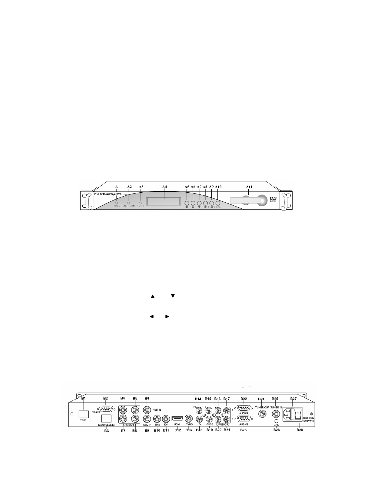
4.1 Front Panel
A1 POWER Power indicator, green light means power is OK
A2 TUNER LOCK Tuner lock indicator, green light means signal is locked; if
there is no light, which means no signal input or wrong
parameters setting.
A3 ALARM Alarm indicator
A4 LCD 2 × 20 character LCD
A5-A10 Operation buttons
〔〕〔〕
are used to up/down pages of menu or
increase/decrease value when edit numbers
〔〕〔〕
are used to move cursor
〔
ENTER〕is used to enter sub menu or confirm operation
〔EXIT〕is used to return previous menu or cancel operation
A11 Common Interface PCMCIA Module slot
4.2 Rear Panel

PBI DCH-5000P
- 6 -
B1 TS/IP IP input/output port
B2 RS-232 serial port for printing information
B3 MANAGEMENT Interface as network management and software
upgrading
B4,B7 ASI2 OUT ASI2 output port
B5,B8 ASI1 OUT ASI1 output port(independently from ASI 1)
B8 ASI1 IN ASI1 input port
B9 ASI2 IN ASI2 input port
B10 SDI2 SDI 2 output port
B11 SDI1 SDI 1output port(same with B11)
B12 HDMI HDMI output port
B13 CVBS CVBS output port(BNC)
B15,B14,B18 Y,Pb,Pr YPbPr output port
B19 CVBS CVBS output port(RCA)
B16,B17 AUDIO1 Audio1 output port (RCA)
B20,B21 AUDIO2 Audio2 output port(RCA)
B22 AUDIO1 Audio1 output port (RS-232, AESEBU digital audio,
XLR balanced/unbalanced)
B23 AUDIO2 Audio2 output port (RS-232)
B24 TUNER OUT Tuner signal loop out
B25 TUNER IN Tuner signal input
B26 GND Grounding terminal
B27 Fuse V250V/2A fuse
B28 Socket AVC 90~250V input
5. Menu Structure and Operation
There is a 2×20 character LCD in front panel. After turn on power, it will show boot
information
First line is product name; Second line is IP address of this device. Press 〔ENTER〕
button to enter main menu:
Main Menu
Inputs Outputs System

PBI DCH-5000P
- 7 -
(1) Input Setup Set input parameters
(2) Output Setup Set output parameters
(3) System Set system parameters
5.1 Inputs Menu
There are three options: Status and DVB-S2:
5.1.1 Status Menu
It contains four options, ASI1, ASI2, TUNER and IP IN, to show the status of signal
input:
ASI1: When signal from ASI1 input port is locked, it will display package format and
code rate; if signal is not locked, it will show Unlock.
ASI2: When signal from ASI2 input port is locked, it will display package format and
code rate; if signal is not locked, it will show Unlock.
TUNER: When signal from tuner input port is locked, it will display package format
and code rate; if signal is not locked, it will show Unlock.
IP IN: When signal from IP input port is locked, it will display package format and
code rate; if signal is not locked, it will show No link.
5.1.2 DVB-S2 Menu
There are 6 options to set QPSK parameters. After signal is locked, the TUNER LOCK
indicator on front panel will turn green.
LNB Frequency: Input LNB frequency
Satellite Frequency: Input downstream frequency of satellite
Symbol Rate: Input symbol rate of satellite
LNB Voltage: select the correct LNB voltage output of the F-connector: Off, 13 V, 18 V. <A>
Inputs
Status DVB-S2
Ethernet

PBI DCH-5000P
- 8 -
LNB 22KHz: activate the LNB 22 kHz control signal to the LNB: On or Off. <B>
DISQEC: Can select OFF/Port A/Port B/Port C/Port D
Note: please contact the local satellite operator for the satellite frequency and symbol rate.
<A> Normally, 13V switches the LNB to receive Vertical/Left hand polarization
while 18V receive Horizontal/Right hand.
<B> Normally, 22KHz control signal switches the LNB to receive high band if any.
5.1.3 Ethernet Menu
(The Ethernet menu is showed only if the IP streaming in/out board is installed and the
TS/IP streaming board is set to “IP IN”. Refer to section 5.2.7.)
The Ethernet connector is for receiving transport stream over IP. The Ethernet
connector has user-configurable IP address, network mask and default gateway. These
must be set to appropriate values for the network over which the transport stream over IP is
received.
Stream IP Addr: Enter the IP address for streaming IP input of the unit.
Stream Netmask: Enter the network sub mask for the subnet to which the unit is
connected for IP streaming traffic.
Stream Gateway: Set the gateway for the network to which the unit is connected
for IP streaming traffic.
Stream Mac Address: factory-set MAC addresses are guaranteed to be unique.
Therefore you cannot configure the address.
Multicast IP Addr: Enter the IP address of the multicast stream for the transport
stream over IP.
Multicase UDP Port: Enter the UDP port number of the TS over IP stream.
Protocol: select the protocol for multicast: UDP or RTP.
Output Smoothing: set the quality of TS which comes from the TS/IP input.
Auto: the bit rate is variable.
Disable: the unit let the TS pass by.
Fixed Rate: the bit rate is fixed.
TS Bit Rate: set the bit rate of the TS comes from the TS/IP input. The setting is
only valid when the output smoothing is configured as Fixed Rate.
5.2 Outputs Menu
Under Outputs Menu, you can monitor and configure the parameters of the CI, AV
decoder, ASI out, ASI2/SDI out, Mux (A), and TS over IP output (B).
Note: (A) The Mux menu is showed only if the functional block is enabled. Refer to section

PBI DCH-5000P
- 9 -
5.2.7.
(B) The Ethernet menu is showed only if the IP streaming in/out board is installed and
the TS/IP streaming board is set to “IP Out”. Refer to section 5.2.7.
5.2.1 BISS Menu
Biss: It includes Biss Mode, Biss 1 Setup and Biss E Setup
Biss Mode:Set Biss mode, can select OFF, Biss E or Biss 1
Biss 1 Key enter:set Biss 1, password is required
Biss E Key enter:set Biss E, ID number and password are required
Biss source: ASI 1 Input, ASI 2 Input, TUNER, CI de-encrypted and IP.
5.2.2 CI Menu
There are two PCMCIA slots for inserting CAM for de-encrypting program from the
input signal.
Before setting CI, ensure the signal from ASI input is locked or the Tuner locks on the
correct Transponder (this depends on in which signal the encrypted program carried). The
‘Tuner Lock’ LED will 'on' in green.
There are 2 submenus: ‘CI Source’ and ‘Setup’ which allow you to set or select the
parameters of the CI.
CI Source: press the <ENTER>-key, then use <
> or < >-key select Tuner or ASI1
input or ASI2 input or BISS or TS/IP input (only when the TS/IP is set “IP In”, refer
section 5.2.7 for details) to set the signal source of descrambling, press <ENTER>-key
to save or press <EXIT>-key to scrap.
Setup: under this sub menu, you can see all program names from the source of CI that
was set in ‘CI Source’ previously. All free programs are marked with ‘Free’ in the first
row.
To select which program to be de-encrypted, press the
< > or < >-key to roll up and
down the program names and press <ENTER>-key to change the status of the
corresponding program (only encrypted program could be selected). Three different
statuses could be set:
Slot 1 (de-encrypted with upper CAM inserted)
Outputs
BISS
CI
Decode
ASI1
ASI2
Ethernet
SDI
Mux

PBI DCH-5000P
- 10 -
Slot 2 (de-encrypted with lower CAM inserted)
Bypass (no de-encryption).
The status will be shown in the first row on the LCD display. Confirm this setup when
leaving this sub menu, press <ENTER>-key to save or press <EXIT>-key to scrap.
The de-encrypted program could be delivered to other functional blocks, like A/V
decoder, ASI1, ASI2, SDI, Mux and TS/IP output (refer to section 5.2.3~5.2.8 for
more).
5.2.3 Decoder
You can configure the parameters of Video and Audio of the program decoded by AV
decoder.
Source: Press the <ENTER>-key and use the <
> or < >-key to roll up or down to
select the signal source of ASI output, there are 5 type of signal source optional:
CI De-encrypted: the de-encrypted transport stream from CI functional block
will be delivered to the ASI output port on the back panel.
TUNER: the transport stream from Tuner block will be delivered to the ASI
output port on the back panel.
ASI1 Input: the transport stream comes from ASI1 input port will be delivered
to the ASI1 output port on the back panel.
ASI2 Input: the transport stream comes from ASI2 input port will be delivered
to the ASI2 output port on the back panel.
Mux TS: the transport stream comes from internal Mux functional block will be
delivered to the ASI output port on the back panel.
(The Mux TS is valid only when the Mux function block is enabled and turned
on. The Mux TS indicates not only the after-multiplexed TS when Mux is
enabled, refer to section 5.2.7 and section 5.3.6 for how to set the Mux
function block.)
Press <ENTER>-key to save or press <EXIT>-key to scrap. A few seconds after the
source being selected, the TS will be delivered to the ASI output port on the back
panel.
Program: under this sub menu, you will see all program names detected by
DCH-5000P. The programs could be coming from ASI input, Tuner, TS/IP input or the
internal CI de-encryption block. Use the <
> or < >-key to roll up or down between
the program names, and use <
>-and < >-key to switch among input sources, where
a number in front of the program name indicates the input source:
A-xxxxx displays the program name, which comes from ASI input.
T-xxxxx displays the program name, which comes from TUNER input.
I -xxxxx displays the program name, which comes from TS/IP input

PBI DCH-5000P
- 11 -
C-xxxxx displays the program name which comes from the CI.
A few seconds after the program being selected, the A/V signal will be delivered to the
related connectors on the back panel.
Video: You can configure the video parameters of programs in this submenu. Press the
<ENTER>-key to confirm or press the <EXIT>-key to cancel.
Video Standard: you can select Auto or SECAM or NTSC or PAL for the
composite video output.
Screen: select the screen mode: 4:3 Full, 16:9 Full or 4:3 Letterbox.
DVB Subtitle Lang: select the language of DVB Subtitle.
EBU Subtitle Lang: select the language of EBU Subtitle.
Subtitle Priority: configure the priority of Subtitle; choose whether DVB or EBU
should be first.
Fail Mode:choose which kind of picture will appear when signal is fail. You can
select Black Screen or No Sync or Still Picture
Audio: You can configure the audio settings in the submenu.
Audio1 Level: use the <
> < > < > < >-keys to modify the audio1 level
within this range: 0~99.
Audio1 Mode: select Stereo, Left, Right or Mono for soundtracks.
Audio1 Language: select the language of the audio.
Audio2 Level: use the <
> < > < > < >-keys to modify the audio2 level
within this range: 0~99.
Audio2 Mode: select Stereo, Left, Right or Mono for soundtracks.
Audio2 Language: select the language of the audio.
Status: It indicates the status of the decoder. It includes PMT, PN, A/V, Video and
Audio.
Program set up: In this menu, you could set the programs, including the BISS list and
output programs.
5.2.4 ASI1
You can configure the settings of ASI1 in this menu.
ASI1 Source: Press the <ENTER>-key and use the <
> or < >-key to roll up or
down to select the signal source of ASI output, there are 5 type of signal source
optional:
CI De-encrypted: the de-encrypted transport stream from CI functional block
will be delivered to the ASI output port on the back panel.
TUNER: the transport stream from Tuner block will be delivered to the ASI

PBI DCH-5000P
- 12 -
output port on the back panel.
ASI1 Input: the transport stream comes from ASI1 input port will be delivered
to the ASI1 output port on the back panel.
ASI2 Input: the transport stream comes from ASI2 input port will be delivered
to the ASI2 output port on the back panel.
Mux TS: the transport stream comes from internal Mux functional block will be
delivered to the ASI output port on the back panel.
BISS De-encrypted: the de-encrypted transport stream from BISS functional
block will be delivered to the ASI output port on the back panel.
(The Mux TS is valid only when the Mux function block is enabled and turned
on. The Mux TS indicates not only the after-multiplexed TS when Mux is
enabled, refer to section 5.2.7 and section 5.3.6 for how to set the Mux
function block.)
Press <ENTER>-key to save or press <EXIT>-key to scrap. A few seconds after the
source being selected, the TS will be delivered to the ASI output port on the back
panel.
5.2.5 ASI2
The same configuration method like section 5.2.4
5.2.6 Mux
Mux Switch: the internal multiplexer could be switched On/Off. The default value is ‘off’.
To activate the re-Multiplexing function, you should turn on this Mux functional block.
Bit Rate: should be set to a specified value that doesn’t exceed the Maximum physical
limit of the output medium. For example, to deliver the multiplexed TS to an 8MHz DVB
256QAM modulator, it should not exceed 55000Kb/s, otherwise overflow occurs.
Output Bit Rate
TS ID: you can configure the TS ID to mark the multiplexed TS. Default value is 1.
Program List: press the <ENTER>-key to enter ‘Mux List’ sub-menu. It shows all
programs detected by DCH-5000P. The programs could be come from ASI input,
Tuner, TS/IP input or the internal CI de-encryption block. Use <
> < >-keys to roll
up the program names, and use <
> < >-keys to switch among input sources, where
a number in front of the program name indicates the input source:
A-xxxxx displays the program name, which comes from ASI input.
T-xxxxx displays the program name, which comes from TUNER input.
I -xxxxx displays the program name, which comes from TS/IP input
C-xxxxx displays the program name which comes from the internal CI functional
block.

PBI DCH-5000P
- 13 -
On ‘Mux List’ sub-menu, on the first row, all encrypted programs are labeled with a ‘$’
sign. All programs that are being selected to be re-multiplexed are labeled as ‘Pass’,
otherwise, the un-selected programs are labeled as ‘Fobrid’. Use <ENTER>-key to
selected or un-selected the program being shown.
When leaving the ‘Mux List’ sub-menu, a new menu will be shown ‘Confirm changed?’
Press <ENTER>-key to validate all programs just be selected to be multiplexed or to
scrap by pressing <EXIT>-key.
After a few seconds, the multiplexed TS will be generated and delivered to the
specified destination(s).
5.2.7 Ethernet
(Note this menu is showed only when the TS/IP streaming is installed and the board is
set to “IP Out”, refer to section 5.3.6 for how to set up.)
The TS/IP Ethernet connector could also be configured as the output of the transport
stream over IP. The parameters listed below must be set to appropriate values for the
network over which the transport stream over IP is broadcasted.
Stream IP Addr: Enter the IP address for streaming IP output of the unit.
Stream Netmask: Enter the network sub mask for the subnet to which the unit is
connected for IP streaming traffic.
Stream Gateway: Set the gateway for the network to which the unit is connected for IP
streaming traffic.
Stream Mac Address: factory-set MAC addresses are guaranteed to unique. Therefore
you cannot configure the address.
Protocol: select the protocol for multicast: UDP or RTP.
TS Pkts Per UDP: set the number of the TS packages encapsulated in one UDP
package. The valid range goes from 1 to 7.
Time To Live: set the number of the routers over which the TS over IP can be
transmitted. The valid range goes from 1 to 5.
Type of Service: select the type of service. There are: Normal, Min Monetary Cost, Max
Reliability, Max Throughput or Min Delay.
Source: select the source of the transport stream over IP streaming output. There are 5
type of source optional:
ASI1 Input
ASI2 Input
CI De-encrypted
TUNER
Mux TS (note the Mux TS is showed only when the Mux function block is
enabled and turned on. The Mux TS indicates not only the after-multiplexed TS

PBI DCH-5000P
- 14 -
when Mux is enabled, refer to section 5.2.7 and section 5.3.6 for how to set the
Mux function block)
BISS De-encrypted
After the operation, the selected transport stream will be delivered to the TS / IP
function block for further operation.
Mode: select the mode of IP stream, you can select DVB or IPTV.
DVB mode: the transport stream which comes from the ‘source’ selected in
previous step will be packed into IP Stream directly. Therefore the IP stream
carries all programs and be delivered to the specified Multicast or Unicast IP
address.
IPTV mode: the transport stream which comes from the ‘source’ selected in
previous step will be de-Muxed to several single programs, and each program
is packed into one IP stream. Therefore each IP stream carries only one
program and be delivered to the specified Multicast or Unicast IP address. You
can configure maximum 6 IPTV channels.
Uni/Multicast Setup: use <ENTER>-key to enter sub-menu. The sub-menu is different
according to different ‘mode’ selected in previous step.
DVB mode
Multicast IP: Enter the IP address of the IP stream for the transport stream over IP
output. You can configure the IP stream output mode in Multicast or Unicast.
Multicast could be established by setting Multicast IP address in the range of
239.255.255.255 to 224.0.0.0.
Unicast could be established with the same settings of Multicast, the only
differences are the Multicast IP address, and should NOT be in the range of
224.0.0.0 to 239.255.255.255, which is for Multicast. Although the display is
'Multicast IP' on the first row, the stream itself is Unicast. The IP address of
receiver device (maybe PC with VLC) needed to be set to as the unicast
address on DCH-5000P, please don't use DHCP to get a dynamic IP address
for receiver device.
Multicast UDP Port: Enter the UDP port number of the TS over IP stream output.
IPTV mode
Max Channels (<=6): you can configure the number of IPTV channel. The valid range
goes from 0 to 6.
After the configuration, you can use <
> < >-keys to roll up and down between the
channels. Each channel could be configured independently.
Channel x: ‘x’ means the channel number. Press <ENTER>-key to go down to the

PBI DCH-5000P
- 15 -
sub-menu. There are 4 sub-menus:
x-Multicast IP: Enter the IP address of the IP stream for the transport stream
over IP output.
You can also configure the IP stream output mode in Multicast or Unicast by
setting Multicast IP address.
x-Multicast Port: Enter the UDP port number of the TS over IP stream output.
x-Switch: each channel could be switched On/Off independently. The default
value is ‘off’. To activate the channel, you should turn on.
x-Program: it shows all programs carried by the transport stream from the
source selected. Press <ENTER>-key and use <
> < >-keys to roll up and
down between the program names, where a number in front of the program
name indicates the input source:
A-xxxxx displays the program name, which signal source is ASI.
T-xxxxx displays the program name, which signal source is TUNER.
I-xxxxx displays the program name which comes from the internal CI
functional block.
C-xxxxx displays the program name which comes from the internal Mux
functional block.
All encrypted programs are labeled with a ‘$’ sign on the first row. Press
<ENTER>-key to the program just be selected to be delivered to the specified
IPTV channel or to scrap by pressing <EXIT>-key.

PBI DCH-5000P
- 16 -
5.3 System Menu
There are seven sub-menus:
5.3.1 Local Setup
Each DCH-5000P has an IP address, a network sub mask and a gateway. These must
be set to an appropriate value for the network.
IP Address: The IP address for the unit.
Network Mask: The network mask for the subnet to which the unit is connected.
Gateway: The gateway for the network to which this unit is connected.
5.3.2 Trap IP Addr
The DCH-5000P provides a Monitor Center IP address. You can set this to be the
same IP address of the Monitor Center, which is typically a PC in order to allow the device to
send messages to the monitor center.
5.3.3 Unit Name
The DCH-5000P allows you to edit the unit name which is displayed on the front panel
LCD. Default name is ‘Digital TV Processor”. The unit name should not be longer than 20
characters in ASCII format.
5.3.4 Properties
Version: show software version of this device
MAC Address: Factory-set MAC address which is guaranteed to be unique. You cannot
configure this address.
Linux OS version: show Linux OS version
ARM SW version: show ARM software version
Decoder version: show Decoder version
FPGA version: show FPGA version
TS/IP IN (or OUT) NIOS: it’s changed when TS/IP board is set to “IP Out” or “IP IN”.
TS/IP IN (or OUT) FPGA: it’s changed when TS/IP board is set to “IP Out” or “IP IN”.
5.3.5 Factory Setting
System
Local
Setup
Trap IP
Addr
Unit
Name
Properties
Factory
Settings
Machine
Type
Optional
Function

PBI DCH-5000P
- 17 -
All the user configurable parameters will be set to the factory default settings, including
IP address and the unit name.
5.3.6 Optional Function
There are two submenus:
External Board Type: Press <ENTER>-key to active the menu, use <
> < >-keys to
configure the TS/IP functional block as ‘IP In’ or ‘IP Out’ or ‘No Exist’, and the option is
exclusive. Press <ENTER>-key to confirm or to scrap by pressing <EXIT>-key.
After the operation, you need reboot the unit to valid the configuration.
IP In: the TS/IP port is configured as input, you can feed transport stream over
IP into the unit. The menu ‘Ethernet’ will be showed under the inputs menu.
IP Out: the TS/IP port is configured as output, you can set the transport stream
over IP output to the IP network. The menu ‘Ethernet’ will be showed under the
outputs menu.
No Exist: the TS/IP port is invalid. Therefore the menu ‘Ethernet’ will not be
showed anywhere.
Mux Function: Press <ENTER>-key to active the menu, use <
> < >-keys to
configure the Mux functional block as ‘Enable’ or ‘Disable’. Press <ENTER>-key to
confirm or to scrap by pressing <EXIT>-key.
5.3.7 Machine Type
This setting is reserved for factory-setting, and you are not allowed to access this
menu.

PBI DCH-5000P
- 18 -
6. Accessory list
DCH-5000P-xx 1pc
CD 1pc
User Manual 1pc
Power Cord 1pc
RCA A/V Cable 1pc
ASI Cable 1pc
Beijing Jaeger Communication Electronic Technology Co.,Ltd.
Pro Broadband Inc.
Tel: +86 (0)10 6263 8833 Fax: +86 (0)10 6263 7776
website: www.pbi-china.com e-mail: mkt@pbicn.com
This document and the information contained in it is the property of Pro Broadband Inc. and
may be the subject of patents pending and granted. It must not be used for commercial
purposes nor copied, disclosed, reproduced, stored in a retrieval system or transmitte
in any form or by any means (electronic, mechanical, photocopying, recording or otherwise),
whether in whole or in part, without Pro Broadband Inc.‘s prior written agreement.
© 2008 Pro Broadband Inc. All rights reserved.

Tel: +86-10-62475893 Fax: +86-10-62473278
Beijing Jaeger Communication Electronic Technology Co., Ltd.
 Loading...