

Page 1

Professional Digital Decoder
User’s Manual
DCH-4000P
http://www.pbi-china.com
Page 2

DCH-4000P User Manual
- 1 -
CONTENT
CONTENT ..................................................................................................................................... - 1 -
1. Warning ...................................................................................................................................... - 2 -
2. Introduction ............................................................................................................................... - 3 -
2.1. Features: ............................................................................................................................... - 3 -
2.2. Options: ................................................................................................................................ - 3 -
3. Appearance Introduction ......................................................................................................... - 4 -
3.1. Front Panel List .................................................................................................................... - 4 -
3.2. Rear Panel List ..................................................................................................................... - 4 -
3.3. Usage of Control Buttons ..................................................................................................... - 5 -
4. Operation on Front Panel ......................................................................................................... - 6 -
4.1. Inputs Menu .......................................................................................................................... - 6 -
4.3. System Menu ....................................................................................................................... - 10 -
5. Frequently Asked Question .................................................................................................... - 12 -
6. Appendix .................................................................................................................................. - 12 -
6.1. Specification ....................................................................................................................... - 12 -
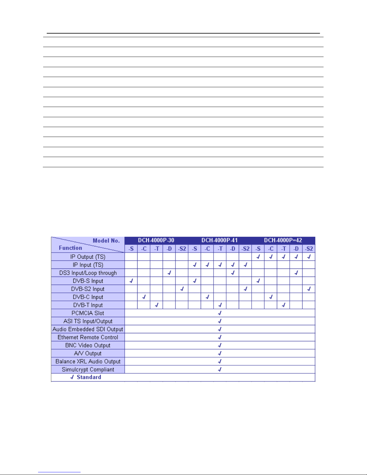
6.2. Option List ............................................................................................................................... 14
7. Technology Support ..................................................................................................................... 15
8. DVB-S2 Input Menu .................................................................................................................... 15
Page 3
DCH-4000P User Manual
- 2 -
1. Warning
* Please refer to the explanation below before operating to avoid user hurt or device
breakdown. Please do NOT power on before safety installation procedure checking.
Product specification and appearance are based on the actual product purchased;
any changes will not be notified accordingly.
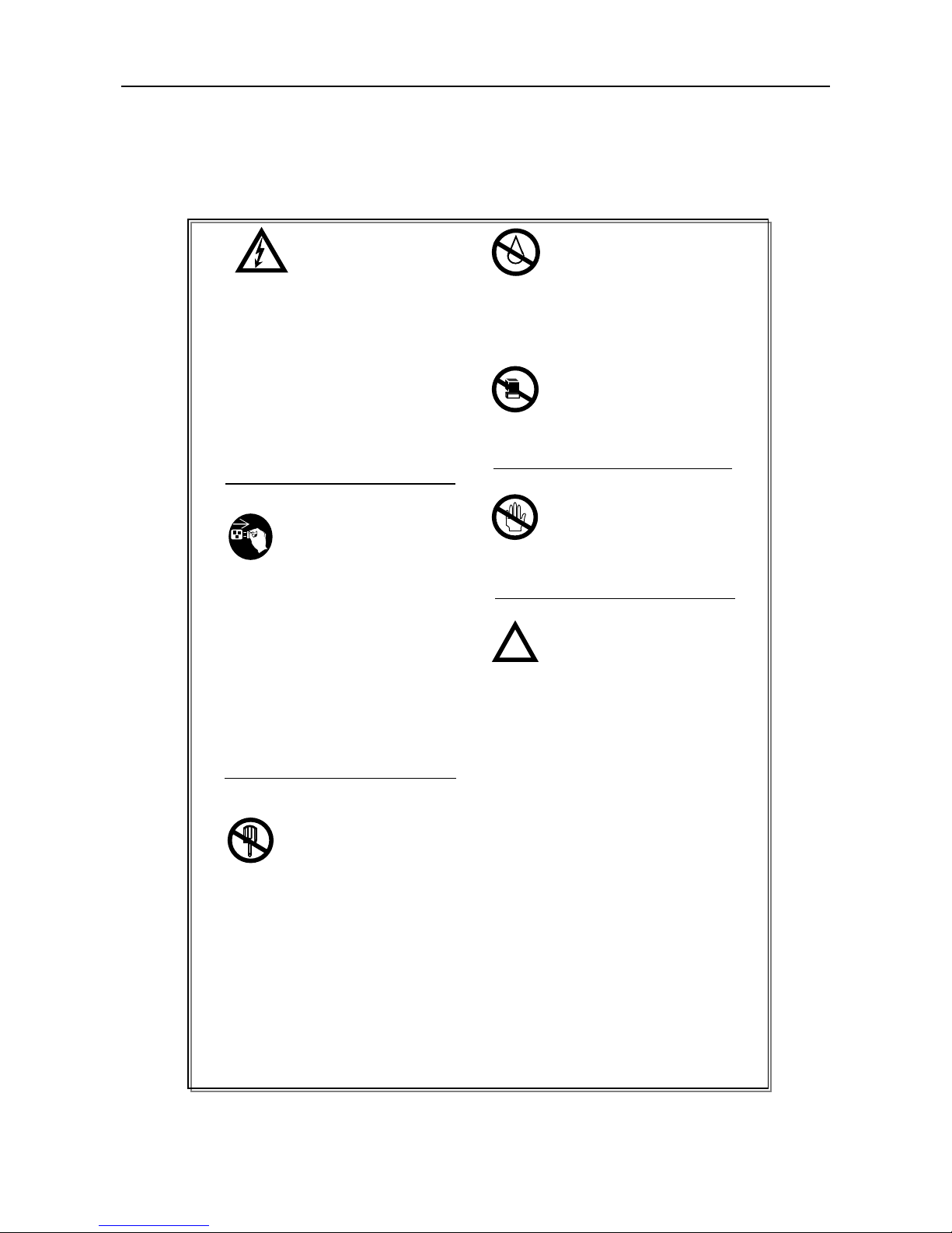
Danger! Electricity!
Please use the outlet with the grounded
pin. If not use the machine for a long
period, please pull out the power plug
from the outlet to avoid the damage by
the lightening or electric wave. Make
proper layout of circuitry to protect the
machine from the destruction by hoof or
extrusion and impact by something laid
on it.
Depart From Dampness!
Do not use the machine in the area with
high humidity or put it in the water or
wet place.
No pressing heavily!
Please do NOT put too much pressure
on the machine.
No touching!
Please do NOT touch the machine during
thunderstorm.
No Dismantle!
1. Please do NOT dismantle the
machine by yourself.
2. Please do NOT change the
parts by yourself. If the machine
cannot work, please call the
agent and professional repairer.
!
!!
!
Urgent instance!
Please pull out the plug in any
following cases:
1. Wire or plug is damaged.
2. Filtered by the liquid, or fall into
water.
3. Poured by rain or water.
4. Drop from a high place or the
chassis is broken.
Page 4

DCH-4000P User Manual
- 3 -
2. Introduction
DCH-4000P is a professional IRD with a variety of input (including DVB over ASI, IP, QPSK,
QAM, COFDM and DS3) and output (CVBS, SDI, ASI, DS3 and IP) combinations. An
appropriate IP port equipped as an option supports DVB over IP applications. LAN control and
monitoring are achieved with TCP/IP, SNMP and HDMS*.
(*Headend Devices Management System, a PBI's proprietary software)
2.1. Features:
Fully complies with MPEG-2, MP@ML and DVB-S/-T/-C standards
IP input or output with UDP/RTP (optional)
Multicast and Unicast on IP
Supports PAL, NTSC or SECAM
Supports various Conditional Access systems
SDI video output with digital audio embedded
Two sets of independent ASI outputs
Automatic PMT update
Compatible with Multiple De-encrypt CI modules
DS3 I/O for TS (optional)
Switchable audio sound track
Teletext VBI, EBU subtitle and DVB subtitle
Upgradeable through LAN
Easy-to-use LCD menu
2.2. Options:
DVB-S, DVB-T or DVB-C tuner input
High Speed 100M Base-T IP output
High Speed 100M Base-T IP input
DS3 I/O card
Page 5

DCH-4000P User Manual
- 4 -
3. Appearance Introduction
3.1. Front Panel List
Figure 3.1 Front Panel of DCH-4000P
(1) PBI logo
(2) Power LED
(3) Tuner lock LED
(4) Alarm LED
(5) LCD ( 20×2 characters )
(6) Control Panel
(7) Common Interface (×2 slots)
3.2. Rear Panel List
Figure 3.2 Rear Panel of DCH-4000P
Page 6

DCH-4000P User Manual
- 5 -
(1) TS/IP Input/Output interface
(2) XRL L interface
(3) XRL R interface
(4) RGB/YUV interface (G/Y)
(5) RGB/YUV interface (B/U)
(6) RGB/YUV interface (R/Y)
(7) CVBS1 interface
(8) L-Audio-R interface
(9) CVBS2 interface
(10) ASI IN interface
(11) ASI/SDI Output interface
(12) ASI Output interface
(13) RS-232 interface
(14) Ethernet interface
(15) Tuner Out interface
(16) Tuner In interface
(17) Power socket
(18) ON/OFF switcher
3.3. Usage of Control Buttons
Figure 3.3 Control Unit
ENTER Call the menu and confirm the performance
EXIT Go back to the previous menu or cancel the operation
& Zapping or switch the options of the menu and modify the values of options
& Move cursor Left /Right
Page 7
DCH-4000P User Manual
- 6 -
4. Operation on Front Panel
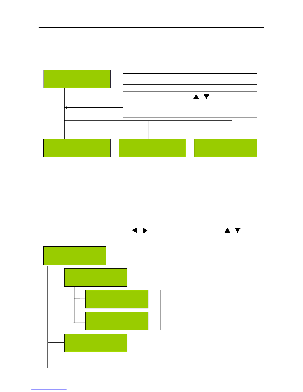
After power on and connecting necessary cables, the LCD will display below information:
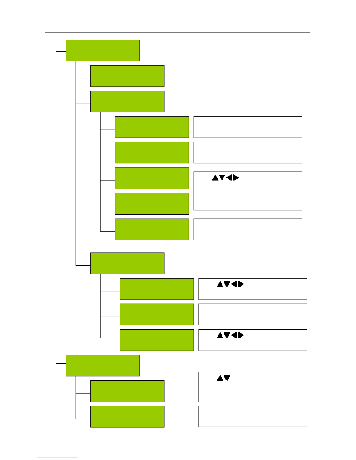
There are three submenus in Main Menu, including Inputs, Outputs and System.
4.1. Inputs Menu
Under Inputs Menu, the user could monitor configure the parameters of the Tuner and IP input
settings.
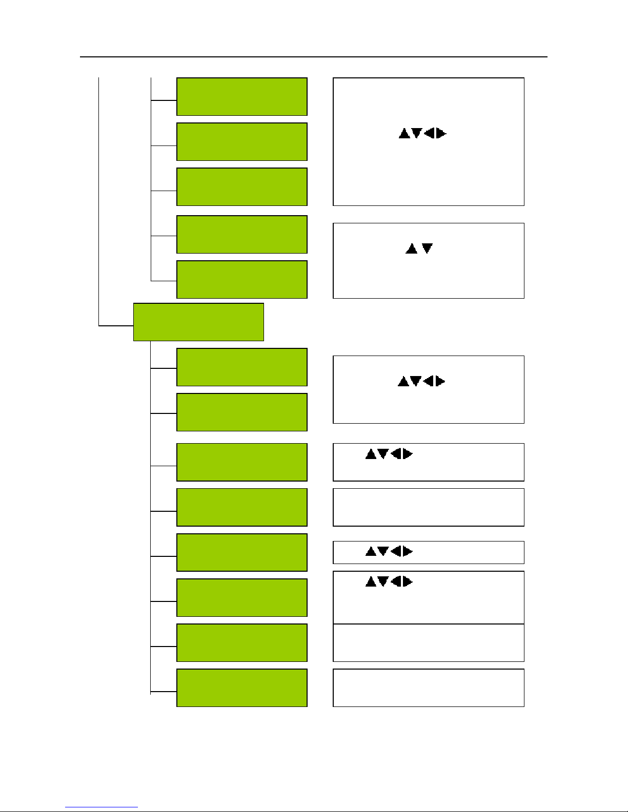
There are three submenus in Inputs menu, including Status, QPSK and Ethernet. Press
ENTER button to enter edit mode. Press & buttons to move cursor and use & button to
modify the value. Press ENTER button to confirm the operation and EXIT button to cancel.
Note: The IP could be configured by user.
Main Menu
System
Main Menu
Inputs
Main Menu
Outputs
DCP-4000P
IP:10.10.70.111
Press ENTER button. Use & to choose menus,
Enter button to enter the menu and EXIT button to back
to the previous menu.
Main Menu
Inputs
Inputs
Status
Inputs
QPSK
ASI unlock
Tuner 0.00000M
IP IN: No Link
IP in unlock
Show the status of inputs and could
not be configured by user.
Page 8
DCH-4000P User Manual
- 7 -
Inputs
Ethernet
LNB Frequency
5150MHz
Satellite Frequency
4043MHz
Symbol Rate
17778KBand
Press ENTER button to enter the edit
mode. Use to key in the
value. Press ENTER to confirm and
EXIT to cancel
LNB Voltage
Off
LNB 22KHz
Off
Press ENTER button to enter the edit
mode. Use to modify the
value. Press ENTER to confirm and
EXIT to cancel.
Source IP Addr
0.0.0.0
Source Network
255.255.255.0
Press ENTER button to enter the edit
mode. Use to modify the
value. Press ENTER to confirm and
EXIT to cancel
Multicast IP Addr
0.0.0.0
Use to modify the value.
Source Mac Address
00:0e:26:ff:aa:41
Show the source Mac address. This
option cannot be configured by user.
Source Gateway
1.0.0.0
Use to modify the source
gateway.
Multicast UDP Port
3000
Use to modify the value
of the UDP Port.
Protocol
UDP
User can configure the protocol to be
UDP or RTP
Output Smoothing
Auto
User can choose Auto, Disable and
Fixed Rate.
Page 9
DCH-4000P User Manual
- 8 -
4.2. Outputs Menu
Under Outputs Menu, the user could configure the settings of output programs, such as the
source signal for CI (CI Source), video standard, aspect ratio, DVB/EBU Subtitle, Audio mode and
language, the source for ASI/SDI output, SDI output with or without audio embedded etc.
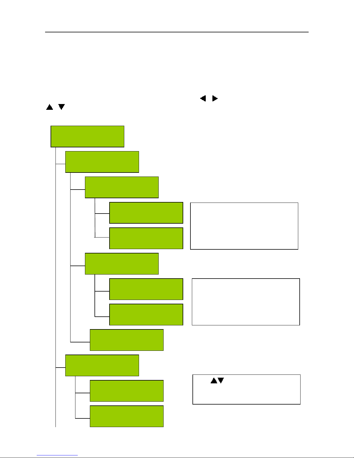
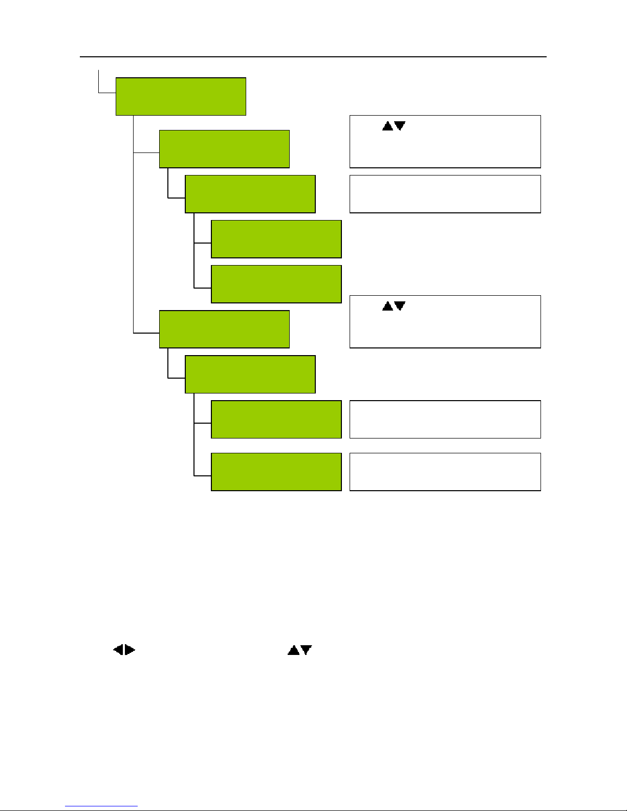
There are five submenus in Outputs menu, including Status, CI, Decoder, ASI and ASI
2/SDI. Press ENTER button to enter edit mode. Use & button to move cursor and use
& button to edit the value. Press ENTER button to confirm the operation and EXIT button to
cancel.
Status
Ethernet
Status
Decoder OK
PMT: 1024 PN: 101
A/V: 80/160
Video: OK
Audio: OK
Show the information of outputs.
Status
CI
CI Slot1
No Module
CI Slot2
No Module
Show the information of CI. If there
is no CAM card in CI Slot, it will
show No Module on the LCD. If
there is, it will show the information
of CAM card.
Outputs
Status
Outputs
CI
CI Source
TUNER
CI
Setup
Use to change the CI source.
There are TUNER, ASI Input and
IP to choose.
Main Menu
Outputs
Page 10
DCH-4000P User Manual
- 9 -
Outputs
Decoder
Decoder
Program
Decoder
Video
Video Standard
Auto
EUB Subtitle lang
eng
Screen
4:3 Full
DVB Subtitle lang
eng
Subtitle Priority
DVB first
There are Auto, SECAM, NTSC
and PAL to choose.
There are 4:3 Full, 16:9 Full and
4:3 Letter box to choose.
Use to change the letters
to spell the language.
e.g.: To choose English subtitle,
please spell eng.
Change the subtitle priority. There are
DVB First and EUB first to choose.
Decoder
Audio
Audio Level
49
Audio Mode
Stereo
Audio lang
eng
Use to modify the audio
level.
There are Stereo, Left, Right and
Mono to choose in Audio mode.
Use to change the letters
to spell the language.
Outputs
ASI
ASI Package Length
Bypass
ASI Source
TUNER
Use to change the ASI Source.
There are Tuner, ASI Input, CI
De-encrypted and IP to choose.
User could select Bypass or 188
.
Page 11
DCH-4000P User Manual
- 10 -
4.3. System Menu
Under System Menu, the user could configure the IP address, unit name of the DCH-4000P, or
recover to the factory default settings, also the user could configure the TS/IP convertor to be IP
input or output.
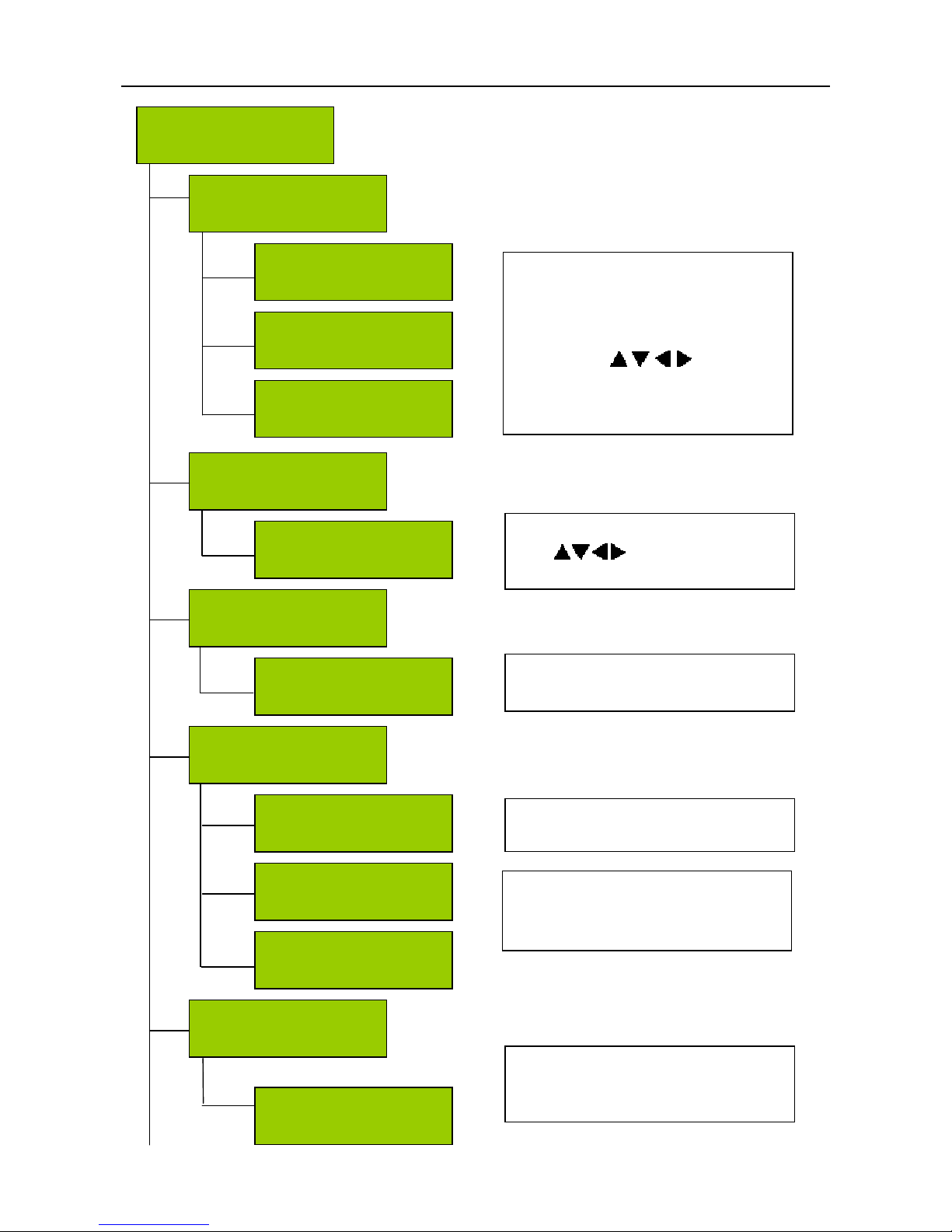
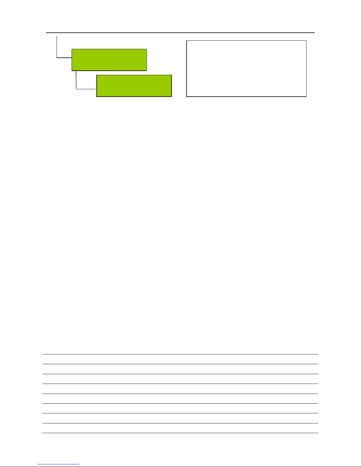
There are six submenus in System menu, including Local Setup, Trap IP Addr, Unit Name,
Properties, Factory Settings and Machine Type. Use ENTER button to enter edit mode.
Press button to move cursor and use button to modify the value. Press ENTER button
to confirm the operation and EXIT button to cancel.
SDI
Setup
Audio DID
Group 1
Embed Audios
None
ASI 2/SDI
SDI
Use to choose SDI, and then
press EXIT. You will find the SDI
Setup option in previous menu
There are Group 1, Group 2,
Group 3 and Group 4 to choose.
You could choose None, One, Two,
and One&Two.
ASI 2
Setup
ASI 2 Package Length
Bypass
ASI 2 Source
TUNER
You could follow the same method to
set the ASI 2 output as ASI output.
ASI 2/SDI
ASI 2
Use to choose ASI 2, and then
press EXIT. You will find the ASI 2
Setup option in previous menu
Outputs
ASI 2/SDI
Page 12
DCH-4000P User Manual
- 11 -
System
Local Setup
IP Address
10.10.70.111
Network Mask
255.255.255.0
Gateway
10.10.70.1
Show the IP address, network mask
and gateway of the DCH-4000P
itself. Press ENTER to enter the edit
mode. Use to modify
them.
System
Trap IP Addr
Trap IP Addr
10.10.70.85
Press ENTER to enter the edit mode.
Use to modify the value
to set the Trap IP address
System
Unit Name
Unit Name
DCH-4000P
The user could change unit name.
The default is DCH-4000P.
System
Properties
MAC Address
00:0e:26:ff:aa:19
Show the DCH-4000P Mac address.
This option cannot be edited.
FW Version
81.00.83
SW Version
03.48.07
Show the FW version and SW
version of DCH-4000P. This option
cannot be edited.
System
Factory Settings
Factory Settings?
ENTER=Yes EXIT=No
Press ENTER button to recover to
factory default settings; Press EXIT
b
utton to cancel.
Main Menu
System
Page 13
DCH-4000P User Manual
- 12 -
5. Frequently Asked Question
1. Why is there no display on LCD?
Answer: Please check whether the power supply is connected well first. If not, insert it well
and switch on.
2. Why is there no input signal?
Answer: Please check whether the input cable in connected well first. If not, insert it well. If it
is connected well, please check whether there is any damage on it. If there is, please change a
good cable.
3. Why can’t the Tuner be locked?
Answer: Please check the settings of the Tuner; be sure the settings are correct to receive the
satellite signal come from the LNB.
4. Why can’t the ASI be locked?
Answer: Please check the BNC cable first, make sure the cable is connected well and there are
programs transmitted to DCH-4000P via the BNC cable.
6. Appendix
6.1. Specification
QPSK Demodulation & FEC Parameters
Input Frequency Range C & Ku Band, 950~2150MHZ
Input Level -25dBm ~ -65dBm
Input Impedance 75ΩF type
Symbol Rate 2~45Mb/s (SCPC or MCPC)
Rolling Off Factory 0.20 or 0.35
Punctured Rates 1/2, 2/3, 3/4, 5/6, 6/7, 7/8
Reeds Salomon Decoding 204, 188, T = 8 & I=12
System
Machine Type
Password
000000
Page 14

DCH-4000P User Manual
- 13 -
DVB-C QAM Demodulation
Connector IEC, Female (7/8MHz) or F Female (6MHz) Input
Input Symbol Rate Range 1~7Mbs (PAL), 1~6Mbps (NTSC)
Demodulation 16/32/64/128/256 QAM
Tuner Bandwidth 6 MHz or 7 MHz or 8 MHz factory optional
FEC Decoder 1/2, 2/3, 3/4, 5/6, 7/8; K=7
Frequency Range 50~860MHz
Digital Signal Input Level -15~15dBmV
Input Impedance 75ΩF-type
DVB-T COFDM Demodulation
Connector IEC, Female (7/8MHz) or F Female (6MHz) Input
1 IF Loop through Yes
Frequency Range 470-862MHz, 174-230MHz
Input Symbol Rate Range 4.98~31.67Mbit/s (8MHz bandwidth)
Constellation QPSK, 16-QAM, 64-QAM
Tuner Bandwidth 8MHz
Digital Signal Input Level -20 to -75dBmV
Input Impedance 75Ωunbalanced
FFT mode 2K/8K
Guard Interval 1/4, 1/8, 1/16, 1/32, off
FEC Code Rate 1/2, 2/3, 3/4, 5/6 and 7/8
DS3 Input
Input Impedance 75Ω
Connector BNC
Maximum Input Code Rate 44.736Mbit/s
Format Unframed Framing according to G.804/G.752 (DS3)
DS3 Loop Through Output
Impedance 75Ω
Maximum Output Code Rate 44.736Mbit/s
Connector BNC
Format Unframed Framing according to G.804/G.752 (DS3)
TS over IP Output
Connector 100base-T RJ45
Output Bit Rate 70Mbits/s Max.
UDP/RTP Multicast or Unicast
Multicast Control Protocol IGMPV2
I/O Interface on back panel
LNB I/O 1×Input, 1×loop through output
RS-232 1×9-pin D-sub male
RJ45 1×Ethernet control port, 1×TS over IP output (factory optional)
Page 15
DCH-4000P User Manual
- 14 -
ASI input 1
ASI output 2×Redundant output
SDI output 1(user optional)
RGB output 1×RCA
CVBS output 1×RCA, 1×BNC
Audio XRL Balance Output 1
General
Operating Temperature
0-45℃
Storage Temperature
-20~70℃
Humidity <85%
Power Supply Ac 90V~260V 50Hz/60Hz
Dimensions 483mm×255mm×44mm
Approximately Net Weight 5Kg
6.2. Option List
Page 16
DCH-4000P User Manual
15
7. Technology Support
ADD: Room216 Floor2B, Dingjun Building,
No. 75 SuZhou Street,
Beijing, 100080, China
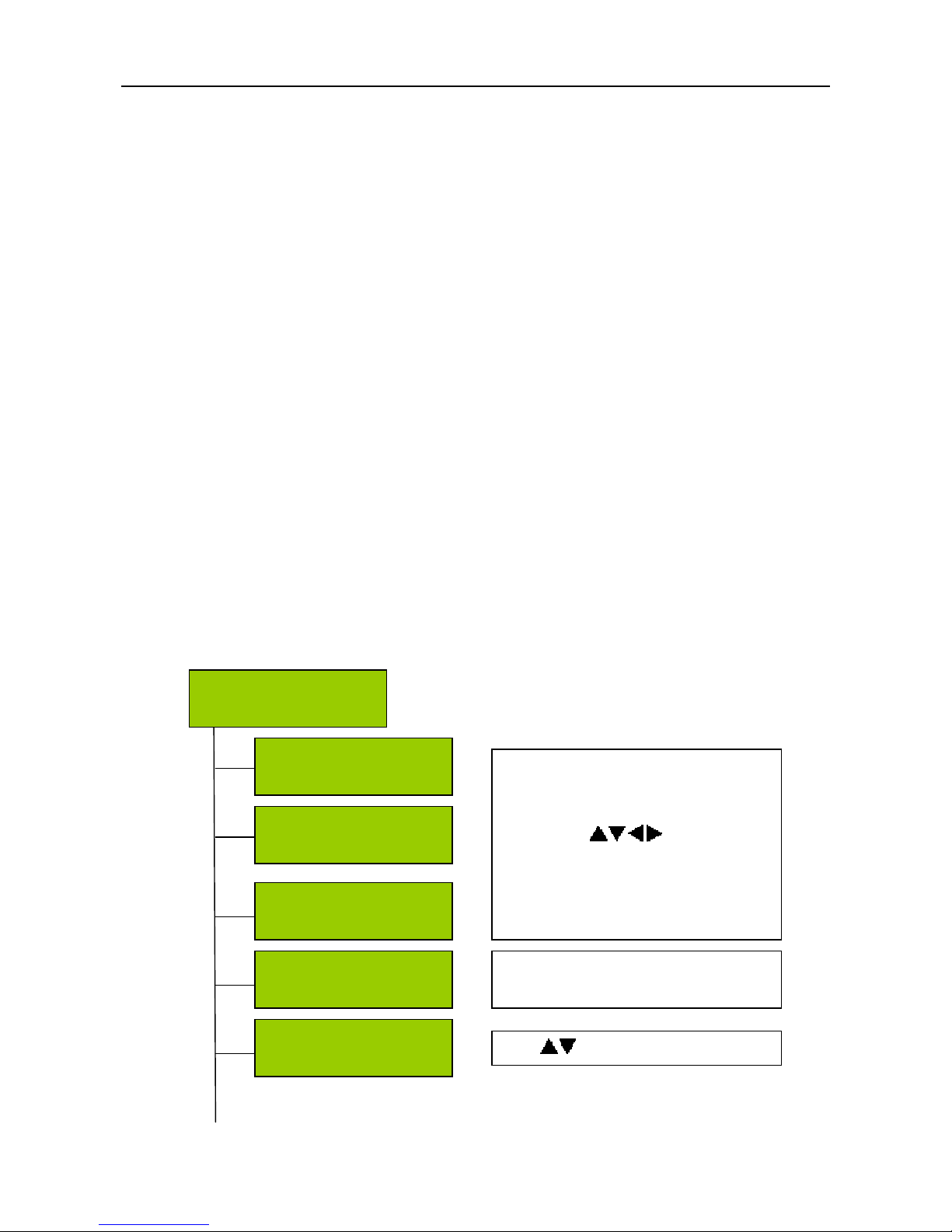
8. DVB-S2 Input Menu
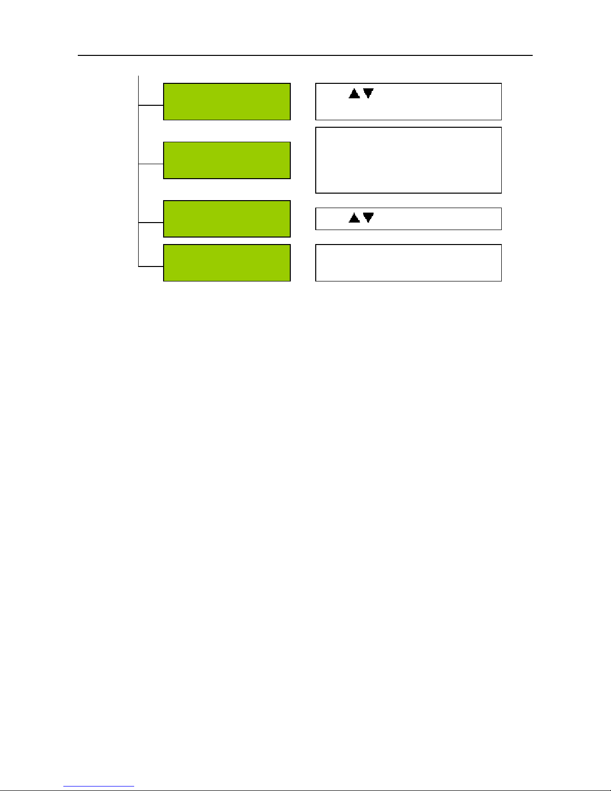
When use DVB-S2 input, there will be some differences in input menu. Please refer to below
menu tree for more details .
LNB Voltage
Off
User can configure Off, 13V and
18V
LNB Frequency
5150MHz
Satellite Frequency
4000MHz
Press ENTER button to enter the edit
mode. Use to modify the
value. Press ENTER to confirm and
EXIT to cancel
Symbol Rate
26850KBaud
Inputs
DVB-S2
LNB 22KHz
Off
Use to change On or Off.
Page 17
DCH-4000P User Manual
16
Demodulator Mode
DVB-S
Use to change demodulator
mode to DVB-S or DVB-S2.
Operation Mode
QPSK 1/2
There are 14 operation modes: eight
QPKS (1/2, 2/3, 3/4, 3/5, 4/5, 5/6,
8/9, 9/10) and six 8PSK (2/3, 3/4,
3/5, 5/6, 8/9, 9/10)
Pilot
On
Use to change demodulator
Roll-off Factor
0.2
There are three factors: 0.2, 0.25 and
0.35.
 Loading...