

Page 1
ON THE QUALITY LINE
CheckMate 3
EN
User Guide
PBI-300042-B
10/2010
Page 2

CheckMate 3 EN User Guide
EN
CheckMate 3
User Guide
PBI-Dansensor A/S
Rønnedevej 18 • DK-4100 Ringsted • Denmark
Tlf.: 57 66 00 88 • Fax: 57 66 00 99
E-mail: [email protected] • Internet: www.pbi-dansensor.com
PBI-Dansensor A/S COPYRIGHT © PBI-300042-B 10/2010
Page 3

2User Guide EN CheckMate 3
PBI-300042-B 10/2010 COPYRIGHT © PBI-Dansensor A/S
Page 4

CheckMate 3 EN User Guide 3
Table of Contents
1. Introduction . . . . . . . . . . . . . . . . . . . . . . . . . . . . . . . . . . . . . . . . 7
Register your product . . . . . . . . . . . . . . . . . . . . . . . . . . . . . . . . . . . . . . . . . .7
About this Manual . . . . . . . . . . . . . . . . . . . . . . . . . . . . . . . . . . . . . . . . . . . . .7
Intended Use of this Manual. . . . . . . . . . . . . . . . . . . . . . . . . . . . . . . . . . . . . . . . . . . . . . . 7
Reservations . . . . . . . . . . . . . . . . . . . . . . . . . . . . . . . . . . . . . . . . . . . . . . . . . . . . . . . . . . . 7
Important! . . . . . . . . . . . . . . . . . . . . . . . . . . . . . . . . . . . . . . . . . . . . . . . . . . . .7
Safety and Use. . . . . . . . . . . . . . . . . . . . . . . . . . . . . . . . . . . . . . . . . . . . . . . . . . . . . . . . . . 7
Notes, cautions and warnings! . . . . . . . . . . . . . . . . . . . . . . . . . . . . . . . . . . .8
Explanation . . . . . . . . . . . . . . . . . . . . . . . . . . . . . . . . . . . . . . . . . . . . . . . . . . . . . . . . . . . . 8
Safety Instructions . . . . . . . . . . . . . . . . . . . . . . . . . . . . . . . . . . . . . . . . . . . . .9
General. . . . . . . . . . . . . . . . . . . . . . . . . . . . . . . . . . . . . . . . . . . . . . . . . . . . . . . . . . . . . . . . 9
Installation . . . . . . . . . . . . . . . . . . . . . . . . . . . . . . . . . . . . . . . . . . . . . . . . . . . . . . . . . . . . . 9
Operation and Maintenance. . . . . . . . . . . . . . . . . . . . . . . . . . . . . . . . . . . . . . . . . . . . . . . 9
CheckMate 3 Overview . . . . . . . . . . . . . . . . . . . . . . . . . . . . . . . . . . . . . . . 10
Setting up . . . . . . . . . . . . . . . . . . . . . . . . . . . . . . . . . . . . . . . . . . . . . . . . . . 12
Connection of additional equipment . . . . . . . . . . . . . . . . . . . . . . . . . . . . . . . . . . . . . . . 13
2. Operation and Maintenance . . . . . . . . . . . . . . . . . . . . . . . . . .15
Modes . . . . . . . . . . . . . . . . . . . . . . . . . . . . . . . . . . . . . . . . . . . . . . . . . . . . . 15
Login . . . . . . . . . . . . . . . . . . . . . . . . . . . . . . . . . . . . . . . . . . . . . . . . . . . . . . 16
Logging off . . . . . . . . . . . . . . . . . . . . . . . . . . . . . . . . . . . . . . . . . . . . . . . . . 17
Daily Start-Up . . . . . . . . . . . . . . . . . . . . . . . . . . . . . . . . . . . . . . . . . . . . . . . 17
Measuring . . . . . . . . . . . . . . . . . . . . . . . . . . . . . . . . . . . . . . . . . . . . . . . . . . 18
Getting the best measurement performance . . . . . . . . . . . . . . . . . . . . . . . . . . . . . . . . 18
Explanation of the “Response time (T
Correction for CO
offset calibration. . . . . . . . . . . . . . . . . . . . . . . . . . . . . . . . . . . . . . . . . . . . . . . . . . . . . 21
O
2
O
sensor temperature sensitivity . . . . . . . . . . . . . . . . . . . . . . . . . . . . . . . . . . . . . . . . . 21
2
sensor temperature sensitivity . . . . . . . . . . . . . . . . . . . . . . . . . . . . . . . . . . . . . . . . 21
CO
2
The Measuring screen. . . . . . . . . . . . . . . . . . . . . . . . . . . . . . . . . . . . . . . . . . . . . . . . . . . 22
Measuring modes . . . . . . . . . . . . . . . . . . . . . . . . . . . . . . . . . . . . . . . . . . . . . . . . . . . . . . 23
Selecting a product for measuring . . . . . . . . . . . . . . . . . . . . . . . . . . . . . . . . . . . . . . . . . 24
Performing a measurement . . . . . . . . . . . . . . . . . . . . . . . . . . . . . . . . . . . . . . . . . . . . . . 26
cross-sensitivity . . . . . . . . . . . . . . . . . . . . . . . . . . . . . . . . . . . . . . . . 20
2
Daily Shut-down . . . . . . . . . . . . . . . . . . . . . . . . . . . . . . . . . . . . . . . . . . . . . 28
Error messages. . . . . . . . . . . . . . . . . . . . . . . . . . . . . . . . . . . . . . . . . . . . . . 28
Cleaning and Maintenance . . . . . . . . . . . . . . . . . . . . . . . . . . . . . . . . . . . . 29
General. . . . . . . . . . . . . . . . . . . . . . . . . . . . . . . . . . . . . . . . . . . . . . . . . . . . . . . . . . . . . . . 29
Cleaning . . . . . . . . . . . . . . . . . . . . . . . . . . . . . . . . . . . . . . . . . . . . . . . . . . . . . . . . . . . . . . 29
Replacing measuring gas hose, filter and needle. . . . . . . . . . . . . . . . . . . . . . . . . . . . . 29
Replacing printer paper. . . . . . . . . . . . . . . . . . . . . . . . . . . . . . . . . . . . . . . . . . . . . . . . . . 30
)” . . . . . . . . . . . . . . . . . . . . . . . . . . . . . . . . . . . 19
95
PBI-Dansensor A/S COPYRIGHT © PBI-300042-B 10/2010
Page 5

4User Guide EN CheckMate 3
3. Menus and Settings . . . . . . . . . . . . . . . . . . . . . . . . . . . . . . . . .31
General . . . . . . . . . . . . . . . . . . . . . . . . . . . . . . . . . . . . . . . . . . . . . . . . . . . . 31
Main menu . . . . . . . . . . . . . . . . . . . . . . . . . . . . . . . . . . . . . . . . . . . . . . . . . 31
Product menu . . . . . . . . . . . . . . . . . . . . . . . . . . . . . . . . . . . . . . . . . . . . . . . 33
Edit product . . . . . . . . . . . . . . . . . . . . . . . . . . . . . . . . . . . . . . . . . . . . . . . . . . . . . . . . . . . 33
New product. . . . . . . . . . . . . . . . . . . . . . . . . . . . . . . . . . . . . . . . . . . . . . . . . . . . . . . . . . . 34
Copy product . . . . . . . . . . . . . . . . . . . . . . . . . . . . . . . . . . . . . . . . . . . . . . . . . . . . . . . . . . 35
Delete product . . . . . . . . . . . . . . . . . . . . . . . . . . . . . . . . . . . . . . . . . . . . . . . . . . . . . . . . . 35
View collected data . . . . . . . . . . . . . . . . . . . . . . . . . . . . . . . . . . . . . . . . . . . . . . . . . . . . . 35
Delete collected data . . . . . . . . . . . . . . . . . . . . . . . . . . . . . . . . . . . . . . . . . . . . . . . . . . . 35
Delete all collected data . . . . . . . . . . . . . . . . . . . . . . . . . . . . . . . . . . . . . . . . . . . . . . . . . 35
Data log . . . . . . . . . . . . . . . . . . . . . . . . . . . . . . . . . . . . . . . . . . . . . . . . . . . . 36
Diagnostic menu. . . . . . . . . . . . . . . . . . . . . . . . . . . . . . . . . . . . . . . . . . . . . 36
General setup . . . . . . . . . . . . . . . . . . . . . . . . . . . . . . . . . . . . . . . . . . . . . . . 37
Data log setup ... . . . . . . . . . . . . . . . . . . . . . . . . . . . . . . . . . . . . . . . . . . . . . . . . . . . . . . . 38
Serial data dump specification. . . . . . . . . . . . . . . . . . . . . . . . . . . . . . . . . . . . . . . . . . . . 39
Network setup ... . . . . . . . . . . . . . . . . . . . . . . . . . . . . . . . . . . . . . . . . . . . . . . . . . . . . . . . 41
Custom fields setup .... . . . . . . . . . . . . . . . . . . . . . . . . . . . . . . . . . . . . . . . . . . . . . . . . . . 41
User setup ... . . . . . . . . . . . . . . . . . . . . . . . . . . . . . . . . . . . . . . . . . . . . . . . . . . . . . . . . . . 42
Access level . . . . . . . . . . . . . . . . . . . . . . . . . . . . . . . . . . . . . . . . . . . . . . . . 43
Calibration. . . . . . . . . . . . . . . . . . . . . . . . . . . . . . . . . . . . . . . . . . . . . . . . . . 44
Offset (20,9%) calibration. . . . . . . . . . . . . . . . . . . . . . . . . . . . . . . . . . . . . . . . . . . . . . . . 44
Export/Import . . . . . . . . . . . . . . . . . . . . . . . . . . . . . . . . . . . . . . . . . . . . . . . 47
Standby . . . . . . . . . . . . . . . . . . . . . . . . . . . . . . . . . . . . . . . . . . . . . . . . . . . . 47
Sleep . . . . . . . . . . . . . . . . . . . . . . . . . . . . . . . . . . . . . . . . . . . . . . . . . . . . . . 48
Language. . . . . . . . . . . . . . . . . . . . . . . . . . . . . . . . . . . . . . . . . . . . . . . . . . . 48
4. Technical Information . . . . . . . . . . . . . . . . . . . . . . . . . . . . . . .49
Technical specifications . . . . . . . . . . . . . . . . . . . . . . . . . . . . . . . . . . . . . . 49
Electrical connections . . . . . . . . . . . . . . . . . . . . . . . . . . . . . . . . . . . . . . . . . . . . . . . . . . . 49
Mechanical data . . . . . . . . . . . . . . . . . . . . . . . . . . . . . . . . . . . . . . . . . . . . . . . . . . . . . . . 49
Connectivity . . . . . . . . . . . . . . . . . . . . . . . . . . . . . . . . . . . . . . . . . . . . . . . . . . . . . . . . . . . 50
Gas connection . . . . . . . . . . . . . . . . . . . . . . . . . . . . . . . . . . . . . . . . . . . . . . . . . . . . . . . . 50
Basic specifications. . . . . . . . . . . . . . . . . . . . . . . . . . . . . . . . . . . . . . . . . . . . . . . . . . . . . 50
Zirconia O
Electrochemical O
sensor . . . . . . . . . . . . . . . . . . . . . . . . . . . . . . . . . . . . . . . . . . . . . . . . . . . . . . . . . . . . 51
CO
2
Accuracy specification (excl. calibration) . . . . . . . . . . . . . . . . . . . . . . . . . . . . . . . . . . . . 52
Standard calibration specification . . . . . . . . . . . . . . . . . . . . . . . . . . . . . . . . . . . . . . . . . 52
Specification conditions . . . . . . . . . . . . . . . . . . . . . . . . . . . . . . . . . . . . . . . . . . . . . . . . . 53
Conformity . . . . . . . . . . . . . . . . . . . . . . . . . . . . . . . . . . . . . . . . . . . . . . . . . . . . . . . . . . . . 53
PBI-300042-B 10/2010 COPYRIGHT © PBI-Dansensor A/S
sensor. . . . . . . . . . . . . . . . . . . . . . . . . . . . . . . . . . . . . . . . . . . . . . . . . . . . . . 51
2
sensor . . . . . . . . . . . . . . . . . . . . . . . . . . . . . . . . . . . . . . . . . . . . . . . 51
2
Page 6

CheckMate 3 EN User Guide 5
Consumable parts and options . . . . . . . . . . . . . . . . . . . . . . . . . . . . . . . . . 54
Ordering items . . . . . . . . . . . . . . . . . . . . . . . . . . . . . . . . . . . . . . . . . . . . . . . . . . . . . . . . . 54
Available User Guides . . . . . . . . . . . . . . . . . . . . . . . . . . . . . . . . . . . . . . . . . . . . . . . . . . . 54
Consumable parts . . . . . . . . . . . . . . . . . . . . . . . . . . . . . . . . . . . . . . . . . . . . . . . . . . . . . . 54
Options . . . . . . . . . . . . . . . . . . . . . . . . . . . . . . . . . . . . . . . . . . . . . . . . . . . . . . . . . . . . . . . 54
Toxic and Hazardous Substances or Elements . . . . . . . . . . . . . . . . . . . . 54
PBI-Dansensor A/S COPYRIGHT © PBI-300042-B 10/2010
Page 7

6User Guide EN CheckMate 3
PBI-300042-B 10/2010 COPYRIGHT © PBI-Dansensor A/S
Page 8

CheckMate 3 EN User Guide 7
1. Introduction
Register your product
Thank you for purchasing a PBI-Dansensor product, we hope that the product will fullfill your
needs.
In order to learn more about our customers and the markets we serve, we kindly ask you to
fill out the product registration form available on-line at
www.pbi-dansensor.com/register
In return we can offer to send important product information to you.
About this Manual
Intended Use of this Manual
• This manual describes the common use and maintenance procedures of the
CheckMate 3 device.
It is intended for the daily users and should be kept with the equipment for reference at all
times.
Reservations
• This manual was written and illustrated using the best possible information available at
the time of publication.
• Any differences between this manual and the equipment reflect improvements introduced
after the publication of the manual.
• Changes, technical inaccuracies and typographic errors will be corrected in subsequent
editions.
• As a part of our policy of continuous improvement, we reserve the right to alter design and
specifications without further notice.
Important!
Safety and Use
• Prior to using the equipment it is assumed that it has been properly installed and
configured as described in this manual.
• The manufacturer cannot be held responsible for any damage caused by incorrect use of
this equipment.
PBI-Dansensor A/S COPYRIGHT © PBI-300042-B 10/2010
Page 9
8User Guide EN CheckMate 3
Notes, cautions and warnings!
Throughout the manual notes, cautions, and warnings are indicated with various icons and
written in bold like the example below:
CAUTION! Always replace a fuse with one of the same size and rating.
Explanation
NOTE! The operator should observe and/or act according to the information in
order to obtain the best possible function of the equipment.
CAUTION! The operator must observe and/or act according to the information in
order to avoid any mechanical or electrical damage to the equipment.
WARNING! The operator must observe and/or act according to the information in
order to avoid any personnel injury.
PBI-300042-B 10/2010 COPYRIGHT © PBI-Dansensor A/S
Page 10

CheckMate 3 EN User Guide 9
Safety Instructions
Personnel operating and maintaining the device must be familiar with all aspects of its
operation and be proficient in maintenance.
Such personnel should review the following precautions to promote safety awareness.
General
• Always refer to the manual before operating or maintaining the equipment.
• Observe all WARNINGS, CAUTIONS and NOTES.
• Do not open the device. In case of technical problems please contact your service
provider.
• Do not cover the machine with a cloth or piece of plastic to protect it from dust, as this
prevents free air circulation around the machine and might lead to overheating.
• Do not expose the equipment to heavy moisture or heat and keep it away from direct
sunlight.
• Never short circuit or remove safety devices.
Installation
• To ensure the best installation with the least technical problems, please install equipment
as described in this manual.
• Never install the equipment in explosive environments.
• Always use correct fittings when connecting gas from the gas bottle.
• Provide adequate space around the equipment for proper ventilation.
• The units are Class 2 appliances and do not need to be connected to an earthed mains
socket-outlet.
• It is the responsibility of the owner and operator(s) of the equipment, that the installation
is made in accordance with local rules and regulations.
• When installing the equipment it is necessary to ensure proper ventilation in the room of
the installation in accordance with requirements from manufacturer.
• The manufacturer cannot be held responsible for any damage caused by incorrect
installation of this equipment.
Operation and Maintenance
• Be sure to disconnect electrical power and unplug the unit before performing any cleaning
or maintenance.
• All panels and protective guards must be in place before operating the equipment.
• When operating or maintaining the equipment always obey the relevant rules and
regulations for workers safety.
• Repair or replace damaged power cords immediately.
• Never block gas outlets or needles.
• Replace needles if they get clogged (e.g. when cutting through septa).
• Do not expose the needles to liquids.
PBI-Dansensor A/S COPYRIGHT © PBI-300042-B 10/2010
Page 11
10 User Guide EN CheckMate 3
7
6
11
3
2
4
5
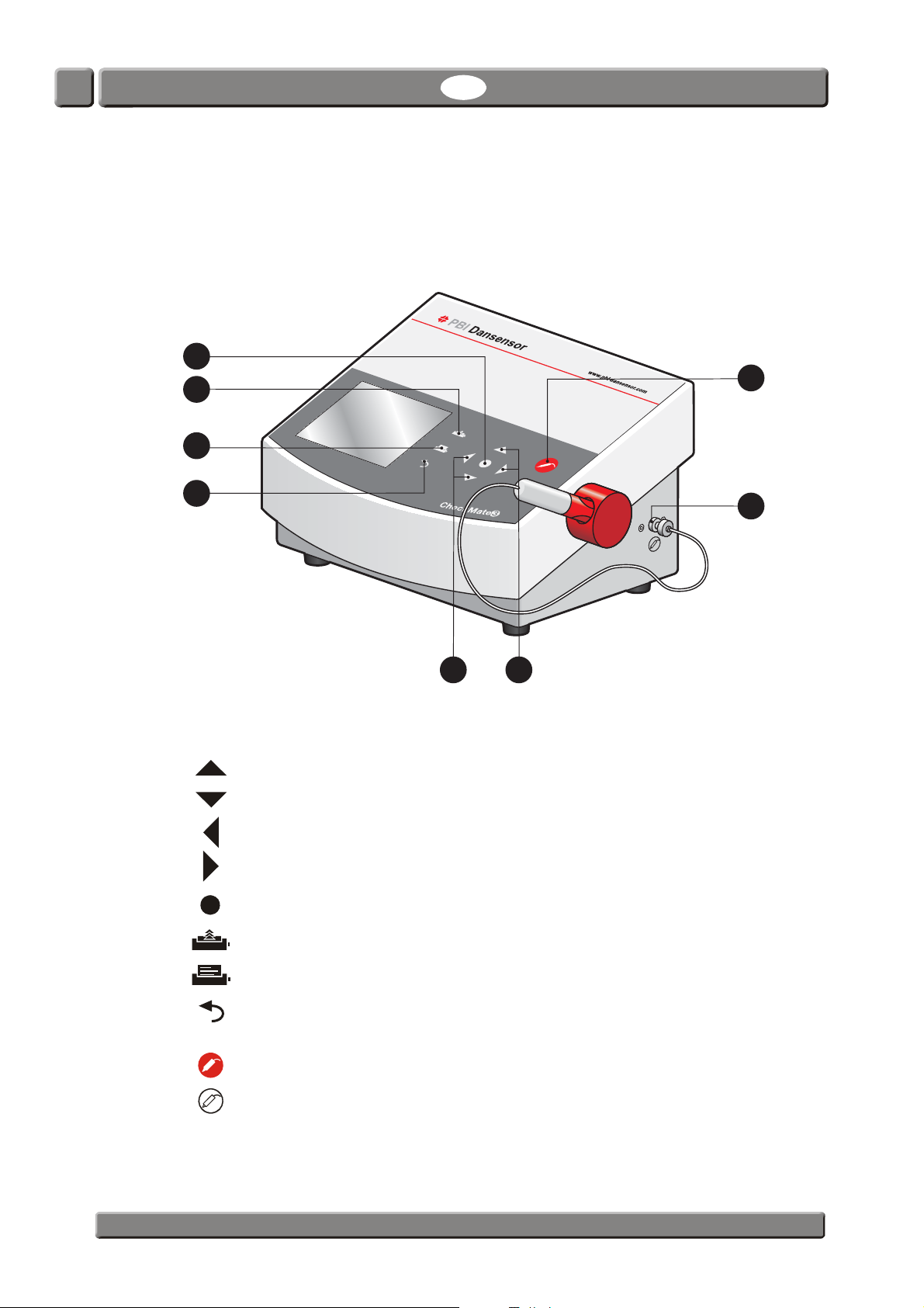
CheckMate 3 Overview
CheckMate 3 is based on an all-in-one concept which together with state-of-the-art sensor
technology ensures fail-safe tests and documentation. With full self-diagnostics, CheckMate
3 detects most common operator faults and offers an efficient automatic report function.
The arrow keys (navigation keys) are used to select menus and functions.
select previous item/scroll up
select next item/scroll down (Contrast adjustment in measuring screen)
go to previous menu or undo a change/selection
go to next menu level
(select)
(Contrast adjustment in measuring screen)
select menu or select/confirm a value
(formfeed) feeding printer paper (version with built-in printer only)
print current screen contents for built-in printer (version with built-in printer only)
undo a selection or a change. If you hold down the key you will automatically
return to the measuring screen or the warm-up screen
(measuring key) starts or stops a measurement
measuring gas inlet for connection of filter and needle set/Smart Pen
PBI-300042-B 10/2010 COPYRIGHT © PBI-Dansensor A/S
Page 12
CheckMate 3 EN User Guide 11
9
10 11
12 13
148
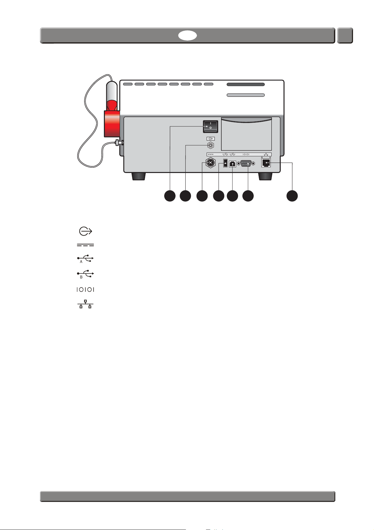
Main switch
Gas outlet
24VDC Power supply connection
USB A port for connection of barcode reader, memory key and keyboard
USB B port for PC communication (for future use)
Serial COM port for dump of data for external data collection
Connection to local computer network (LAN) for external data collection
PBI-Dansensor A/S COPYRIGHT © PBI-300042-B 10/2010
Page 13
12 User Guide EN CheckMate 3
2
1
3
5
4
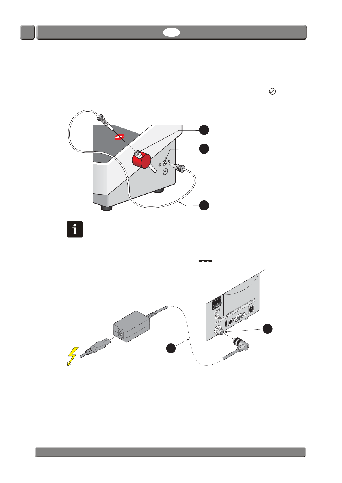
Setting up
1. Place the device on a level and stable surface.
2. Connect the supplied needle set
right side of the device as shown below, then place the needle in the holder
NOTE! It is not possible to fit the needle set without a filter on the measuring
gas inlet. Make sure that all connections are pressed firmly and carefully
together, as leaks will compromise the measurement results.
3. Connect the power supply between the main power supply outlet and the 24 VDC
connection
at the back of the device (labelled ).
to the measuring gas inlet (labelled ) on the
.
4. Starting up and use of the device is described in Se afsnit 2 "Operation and
Maintenance" på side 15.
PBI-300042-B 10/2010 COPYRIGHT © PBI-Dansensor A/S
Page 14
CheckMate 3 EN User Guide 13
2
1
3
4
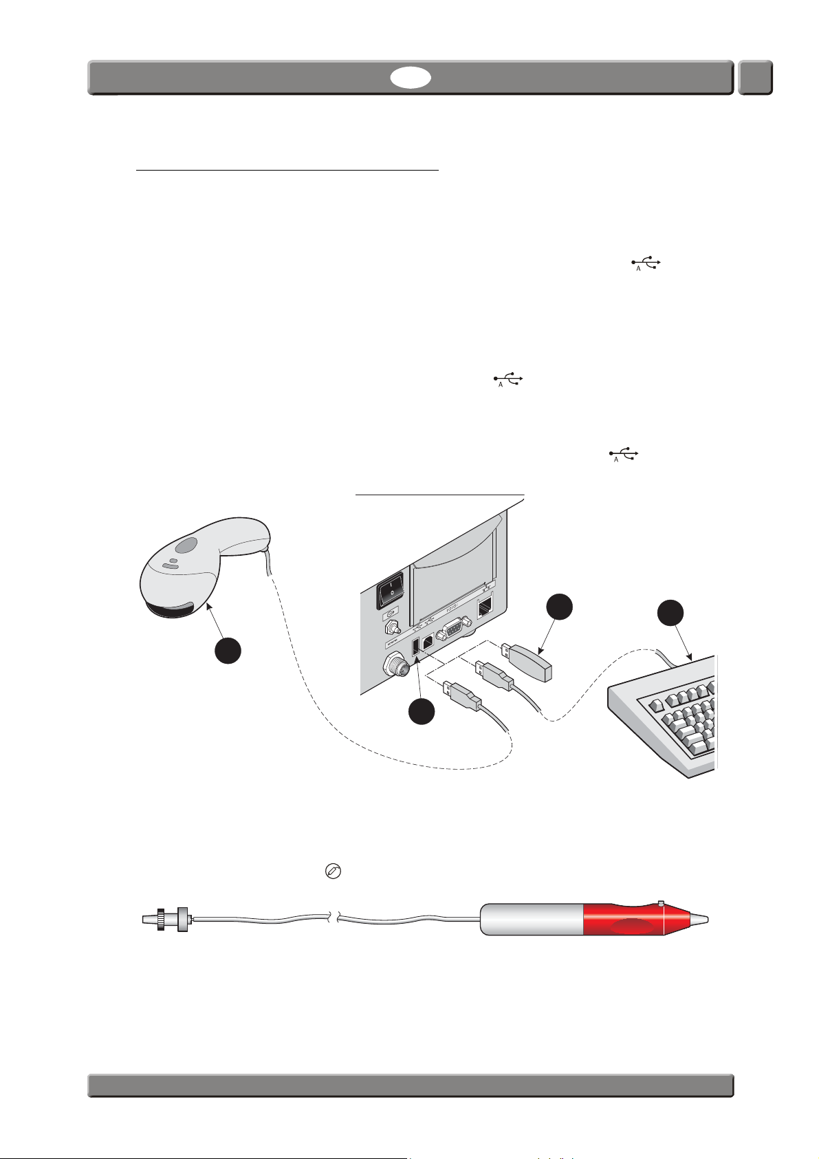
Connection of additional equipment
Barcode reader
It is possible to connect a barcode scanner to CheckMate 3. The barcode scanner must
be a USB type and we recommend using a “Datalogic Heron D130” barcode scanner.
The barcode scanner must be connected to the USB A connector
back of the device.
The barcode scanner is avaliable as an option - see "Options" on page 54.
(labelled ) at the
USB Memory Key
When importing and exporting data you may use a USB memory key . The memory key
must be connected to the USB A connector
(labelled ) at the back of the device.
USB Keyboard
A keyboard can be connected to the device for keying in various data. The keyboard must
be a USB type and it can be connected to the USB A connector
of the device.
(labelled ) at the back
SmartPen
SmartPen is an optional needle retainer/measuring gas extractor with built-in protection and
lock. The SmartPen replaces the standard needle set and must be connected to the
measuring gas inlet (labelled ) on the right side of the device.
PBI-Dansensor A/S COPYRIGHT © PBI-300042-B 10/2010
Page 15

14 User Guide EN CheckMate 3
PBI-300042-B 10/2010 COPYRIGHT © PBI-Dansensor A/S
Page 16
CheckMate 3 EN User Guide 15
Standby
13:46
08/17/06
Sleep
13:46
08/17/06
Meat 400 gr.
Product Menu
08/17/06 13:46
%
O
2
%
CO
2
Press to measure
0,482 29,5
70,0
Product: 47
Meat 400 gr.
Measuring mode: Manual spot
Product Menu
08/17/06 13:46
%
O
2
%
CO
2
29,5
70,0
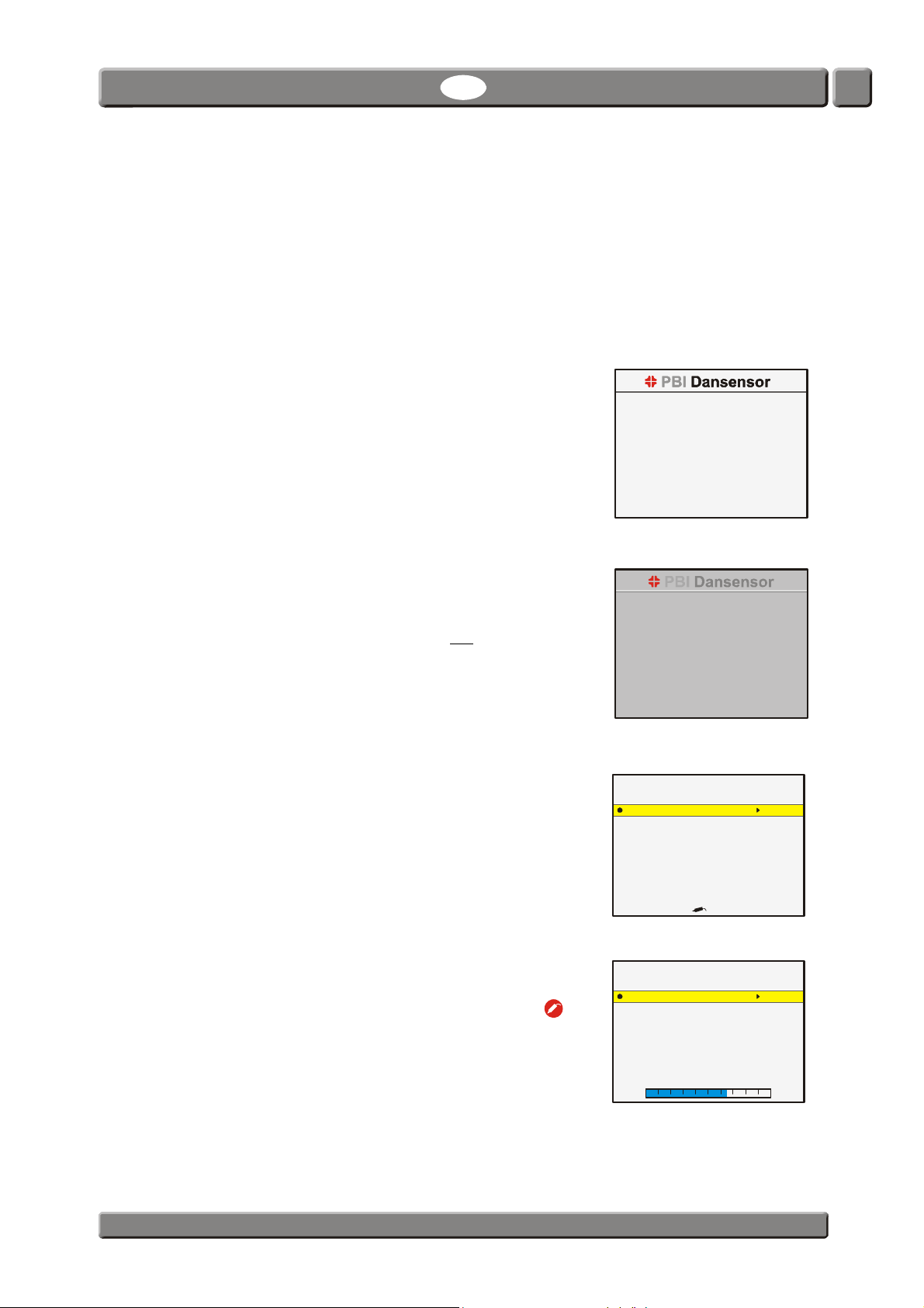
2. Operation and Maintenance
Modes
The device can be in one of 5 modes:
Switched off Power supply disconnected.
Standby mode Display shows the Standby screen.
User has been logged off (if login is
required).
Sensor temperature is maintained.
Standby mode settings are set in chapter
"General setup" on page 37 - see side 37
for details.
Sleep mode Display shows the Sleep screen.
User has been logged off (if login is
required).
Sensor temperature is not
maintained.
Sleep mode settings are set in chapter
"General setup" on page 37 - see side 37
for details.
Ready mode Display will normally show the measuring
screen.
Sensor has correct temperature.
Measuring mode Display will normally show the measuring
screen.
Measuring has been started on the key.
While measuring the display will
continuously show measurement values.
When in “Manual spot” measuring mode a
progress bar is displayed in the bottom of
the screen.
Product: 47
Measuring mode: Manual spot
Bal
0,482
Bal
PBI-Dansensor A/S COPYRIGHT © PBI-300042-B 10/2010
Page 17
16 User Guide EN CheckMate 3
Log in
USER1
USER2
USER3
13:46
08/17/06
Log in
13:46
08/17/06
AB
HI
OP
VW
X
OK
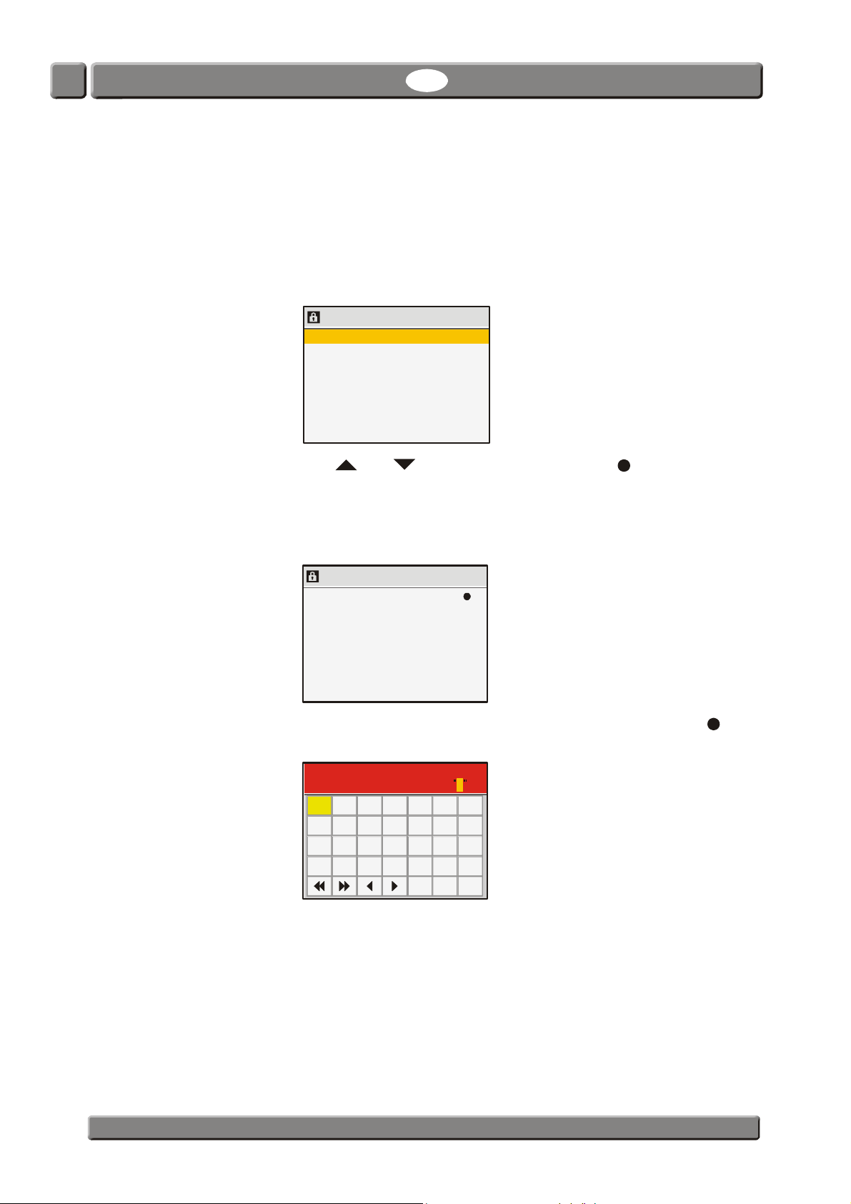
Login
Different levels of login can be set up:
No login At start-up the device will automatically run the self-test and warm-
up period and when finished it changes to show the measuring
screen and will be ready for measuring.
User login At start-up the display will show the list of users.
Use and keys to select user and press key to confirm.
Now the device will run the self-test and warm-up period and when
finished it changes to show the measuring screen and will be ready
for measuring.
Login with User ID At start-up the display will look like this:
Scan user barcode or press
Either use barcode scanner (option) to scan User ID or press to
bring up the touch screen keyboard.
Enter user id
CDEFG
JKLMN
QRSTU
YZ .
Ins Del
NOTE! If you forget your User ID you can always log in using
57670124 as your User ID.
Enter the User ID by means of the touch screen keyboard or the
external keyboard (option). Confirm by pressing the OK key.
Now the device will run the self-test and warm-up period and when
finished it changes to show the measuring screen and will be ready
for measuring.
See Se afsnit "User setup ..." på side 42 for details about user and login settings.
PBI-300042-B 10/2010 COPYRIGHT © PBI-Dansensor A/S
Page 18
CheckMate 3 EN User Guide 17
Heating
Time left XX min
Product: 47
Meat 400 gr.
Measuring mode: Manual spot
Product Menu
08/17/06 13:46
Product: 47
Meat 400 gr.
Measuring mode: Manual spot
Product Menu
08/17/06 13:46
%
O
2
%
CO
2
Press to measure
0,482 29,5
70,0
Logging off
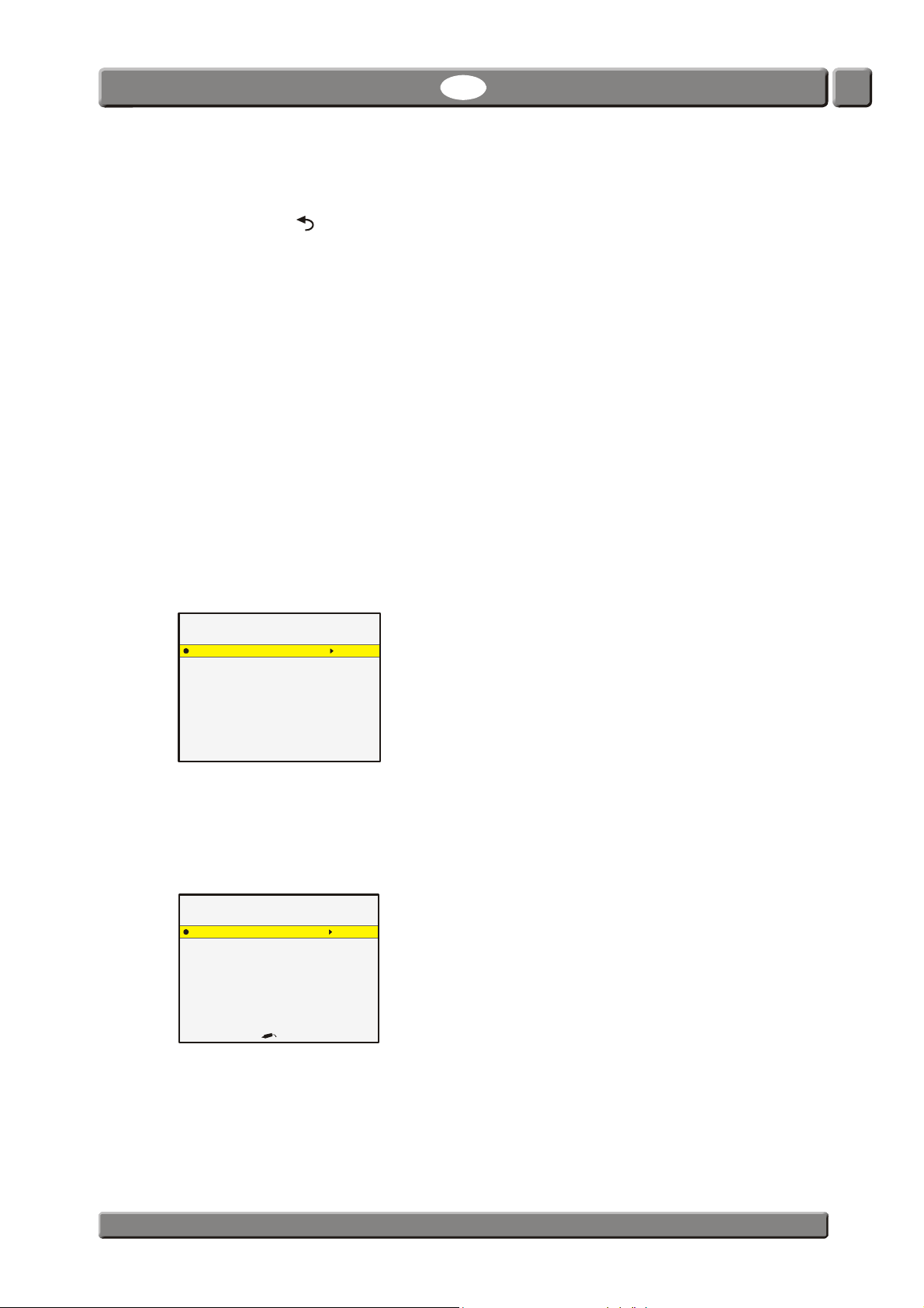
To log off press the key from the measuring screen.
When device is switched into Standby or Sleep mode either automatically or when manually
selected from the “Main menu”, current user will be logged off.
Daily Start-Up
At the start of the working day the device will normally be in one of the following modes:
•Switched Off
• Standby mode
• Sleep mode
Starting the device from the either of the three modes is described in the following:
1. If device is switched off apply power to it.
If device is in either Standby or Sleep mode simply touch the screen.
2. If no login is required the device will start up and automatically run a self-test and warm-
up period of approx. 10 min.
PBI-Dansensor A/S COPYRIGHT © PBI-300042-B 10/2010
If device is started from Standby mode the sensor temperature has been maintained and
the device will be ready after max. 1 min.
3. If User login or login with User ID is required, login as described in "Login" on page 16.
4. After a successful login the device runs the self-test and warm-up period and when
finished the display changes to show the measuring screen.
Bal
5. Now the device is ready to begin measuring.
Page 19

18 User Guide EN CheckMate 3
Measuring
Getting the best measurement performance
There are a number of factors to take into consideration when measuring O2 and CO2
gasses.
The following guidelines should help you to obtain the best possible measurement accuracy
and performance from the CheckMate 3 device.
The device uses either a Zirconia (Zr) based O
The electrochemical (EC) sensor has some limitations compared to the Zirconia based
sensor with regards to response time and cross sensitivity for CO
the CheckMate 3 provides advanced Speed-Up functions in software allowing measurement
times down to 7 secs. For devices with built-in CO
reducing the effects of cross sensitivity to CO
The CO
sensor (if installed) is of the Non Dispersive Infrared (NDIR) type.
2
Both sensors are temperature- and pressure compensated in software. However
temperature compensation requires stabilizing internally for some time.
In spite of the above efforts there are still limitations to what can be physically achieved.
To get the most out of your device, we strongly recommend that you read these next pages to
familiarize yourself with the various conditions, which may have impact on the
measurements.
sensor or an electrochemical (EC) O2 sensor.
2
gasses. Due to this fact
2
sensors we also incorporate a scheme for
2
.
2
PBI-300042-B 10/2010 COPYRIGHT © PBI-Dansensor A/S
Page 20
CheckMate 3 EN User Guide 19
O reading
[%]
2
time [sec]
T=0
Start value
Difference = Start value "True" value
T valu
95
e = Start value (0.95*Difference)
T value
95
"True" value
T=7
(1. measurement) (2. measurement)
T=14
Difference
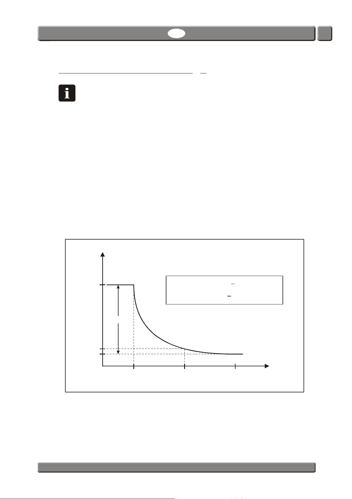
Explanation of the “Response time (T95)”
NOTE! Only valid for devices with an Electro-chemical (EC) O2 sensor.
According to the specifications the Electro-chemical (EC) O
) of 7 sec.
(T
95
sensor has a Response time
2
This means that when performing consecutive measurements in areas with large
differences in the O
concentrations, the device will as a minimum reach 95% of the “true”
2
value during the first measurement (7 sec.).
Example:
(See illustration below):
• Last measurement was performed in i.e. 20.9% O
• The following value to be measured is 1.0% O
• Difference is:
20.9 - 1.0 = 19.9% O
2
• The expected read-out value after first measuring is:
20.9 - (0.95 * 19.9) = 2.0% O
2
2
2
Consequently this means that if there is a large difference in the O2 concentrations between
two consecutive measurements, multiple measurements must be performed to obtain a
more accurate result.
PBI-Dansensor A/S COPYRIGHT © PBI-300042-B 10/2010
Page 21
20 User Guide EN CheckMate 3
"True" O value = Read-out value - correction
2
CO
2
10%
0000.000.000.070.100.100.100.100.100.10
00 004 009 013 016 018 019 019 020 020
00 000 007 007 013 013 021 023 027 027
0 0 0 00 0 11 0 11 0 11 0 11 0 16 0 16 0 20 0 20
0150150150.210,270,27
0000
0.18 0.18 0.33 0.33
0.11 0.11 0.30 0.30
0.00 0.24 0.24
0.00 0.14 0.14
0.00 0.00 0.00 0.00 0.00 0.00 0.00 0.00 0.00 0.00
0.2 % .
0.4 % .
0.8 % .
1.2 % .
1.6 %
2.0 %
2.4 %
2.8 %
3.2 %
3.6 %
4.0 %
0.........
0.........
0.........
0.00 0.00 0.00 0.00 . . .
0.00 0.00 0.00 0.00 0.00 0.00 .18 .26 .33 .33
0.00 0.00 0.00 0.00 0.00 0.00
0.00 0.00 0.00 0.00 0.00 0.00
0.00 0.00 0.00 0.00 0.00 0.00 0.00
0.00 0.00 0.00 0.00 0.00 0.00 0.00
20% 30% 40% 50% 60% 70% 80% 90% 95%
O
2
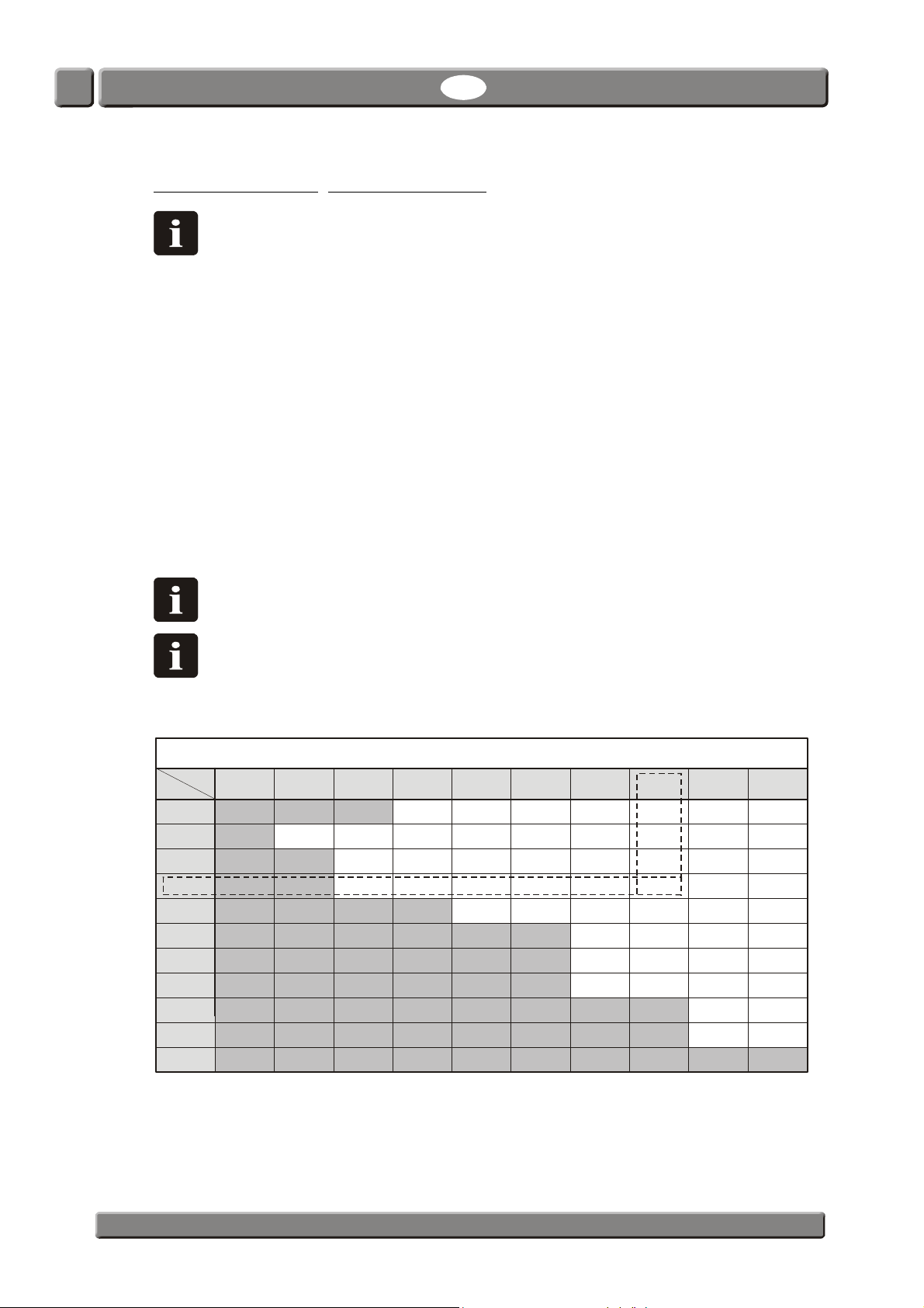
Correction for CO2 cross-sensitivity
NOTE! Only valid for devices with an Electro-chemical (EC) O2 sensor and without
CO
sensor.
2
Due to the Electro-chemical (EC) O
sensor’s cross-sensitivity to CO2, you must manually
2
compensate for the read-out value using the appropriate correction factor from the table
below to obtain a more accurate result.
Example:
• Measurement performed in:
80% CO
• Display read-out value is:
1.2% O
• Correction factor according to table is:
0.16 (marked in table).
• “True” value is:
1.2 - 0.16 = 1.04% O
2
2
2
NOTE! For values in-between table values you will have to interpolate.
NOTE! Read-out values will always lie within specifications (see "Technical
specifications" on page 49) but using manual compensation will ensure more
accurate results.
PBI-300042-B 10/2010 COPYRIGHT © PBI-Dansensor A/S
Page 22
CheckMate 3 EN User Guide 21
O2 offset calibration
NOTE! Only valid for devices with an Electro-chemical (EC) O2 sensor.
An electrochemical (EC) sensor is to be treated as a wearing part as the chemistry inside
wears proportionally to the amount of O
We therefore recommend that you perform daily offset (20.9%) calibrations before starting
measurements.
See "Offset (20,9%) calibration" on page 44 for details.
NOTE As a minimum weekly offset calibration is required to retain the 12 months
calibration interval!
seen during its lifetime.
2
NOTE! If device is used entirely at very high O
lifetime will be reduced proportionally. At O
concentrations above 20.9% the
2
levels up to 20.9% the normal lifetime
2
is approximately two years.
O2 sensor temperature sensitivity
NOTE! Only valid for devices with an Electro-chemical (EC) O2 sensor.
Due to the sensor design the readout will be affected when moving the device from cold to
warm temperatures or vice versa. Normally for compensation to work properly the device
must be stabilized at the current ambient temperature for some time (up to 1-2 hours)
However if you cannot wait for this time, use short stabilizing time, for example 10-15 min.,
and perform an offset (20.9%) calibration of the O
series until device has stabilized. This will bring the calibration back in line with current
response.
NOTE! When entering another ambient temperature area, the device must again be
offset calibrated before use to ensure proper accuracy.
The sensor is also slower in response in cold environments so for better accuracy you should
measure the values twice and skip first measurement (though the first measurement will
comply with T
). Alternatively select longer measuring periods in the product setup for the
95
particular measurements.
sensor right before each measurement
2
CO2 sensor temperature sensitivity
The CO2 measurements however has faster response when changing ambient temperature
zones so if you are only interested in measuring the CO
offset but can start the CO
measurements right away.
2
PBI-Dansensor A/S COPYRIGHT © PBI-300042-B 10/2010
values, you need not recalibrate O2
2
Page 23
22 User Guide EN CheckMate 3
Product: 47
Meat 400 gr.
Product Menu
08/17/06 13:46
%
O
2
%
CO
2
Press to measure
2,49
72,4
The Measuring screen
Measuring mode: Manual spot
1
2
25,1
3
Bal
4
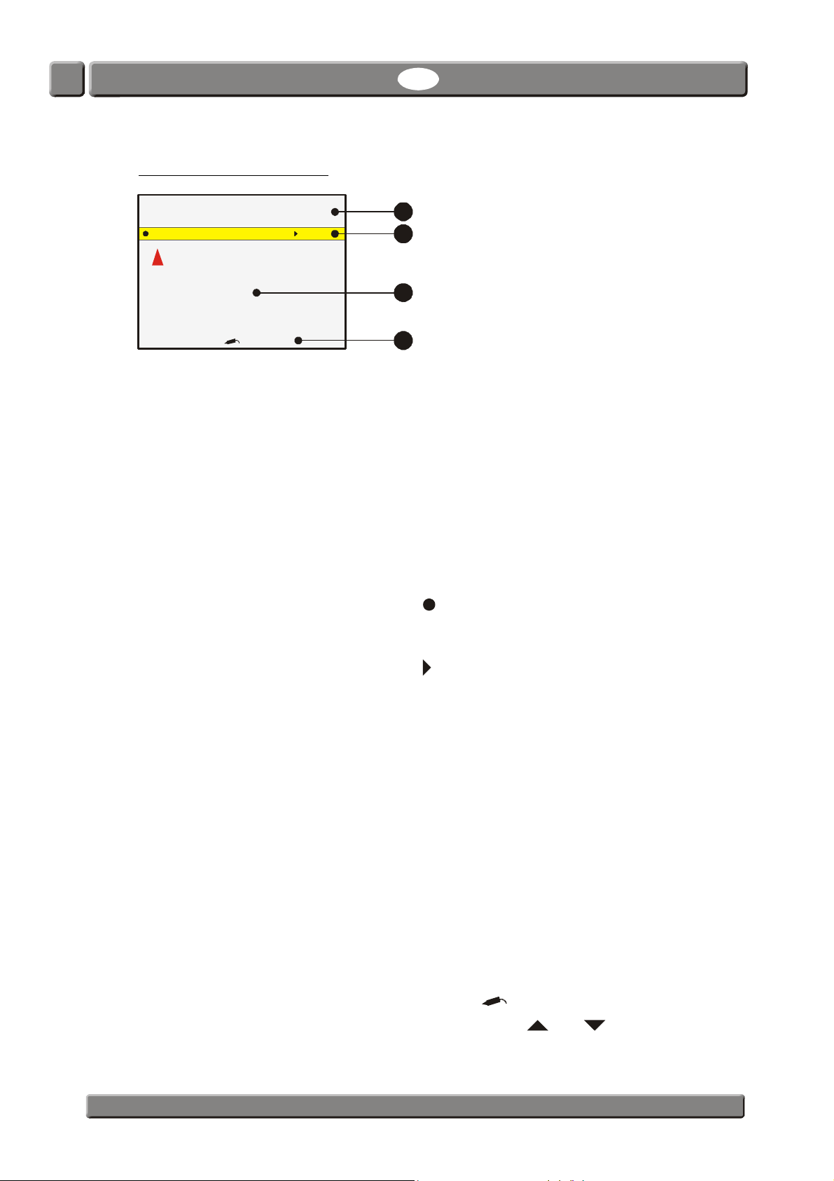
Upper section The upper section of the measuring screen displays the
current date and time, currently selected product number,
product name and product measuring mode.
After each measurement perfomed in either Manual spot or
Auto spot mode the section will display the text Press here to
mark measurement as invalid on an orange background.
Pressing anywhere on the screen will subsequently save the
recent measurement as invalid in the data log.
Function can be disabled - see "Data log setup ..." on page 38
for details.
Yellow bar Shows the functions available from the measuring screen:
Pressing the key takes you to the Last used products
screen (see "Selecting a product for measuring" on page 24
for details).
Measurement section This section displays the result of the recent measurement.
Bottom Shows required user operation or measuring status f.ex.
When display shows the measuring screen you can use the and keys to adjust
PBI-300042-B 10/2010 COPYRIGHT © PBI-Dansensor A/S
screen contrast.
Pressing the key takes you to the Main menu screen
(see "Main menu" on page 31 for details).
Only values selected for display in the product set-up are
displayed - see "Edit product" on page 33 for details.
Text colors indicate whether or not a value has exceeded an
alarm limit:
Black indicates that the result is either within limit or
that no limit is defined for this gas.
Red indicates that the gas concentration has
exceeded an alarm value. The arrow symbol in
front of the value indicates whether it is an upper
or lower alarm.
During heating up the remaining heating time is also
displayed in this area.
“Data required. Press “ or “Measuring”.
Page 24
CheckMate 3 EN User Guide 23
Measuring modes
Four different measuring modes are available:
Manual spot Press key to start the measuring.
The measuring stops automatically after the set-up product measuring
time.
Auto spot The measuring starts automatically when the measured gas is different
from 20.9% O
When the gas measuring is stable, it stops automatically.
To stop measuring manually press key.
Intermittent Press key to start the measuring.
The device will now perform continuous measurements at fixed intervals
until it is stopped again by pressing the key.
The measurement time for each measurement and the time interval
between measurements are set up in the product set-up menu.
Continuous Press key to start the measuring.
+/- 1.5%.
2
The unit will now perform continuous measurements until it is stopped
again by pressing the key.
NOTE! Even though the pump is high quality, it is recommended to stop
Continuous/Auto spot measurements when not used for longer periods.
The various measuring mode parameters are set up in the product set-up menu.
See "Edit product" on page 33 for details.
PBI-Dansensor A/S COPYRIGHT © PBI-300042-B 10/2010
Page 25
24 User Guide EN CheckMate 3
Find pro duct
47: Meat 400 gr.
100: Ham 200g r.
99: Food
9999: Jun k fo od
All products. Name order
Product number
Product name
Product barcode
1:
5:
7:
8:
Sausage
Short Auto
Test 1
Meat 400gr.
Selecting a product for measuring
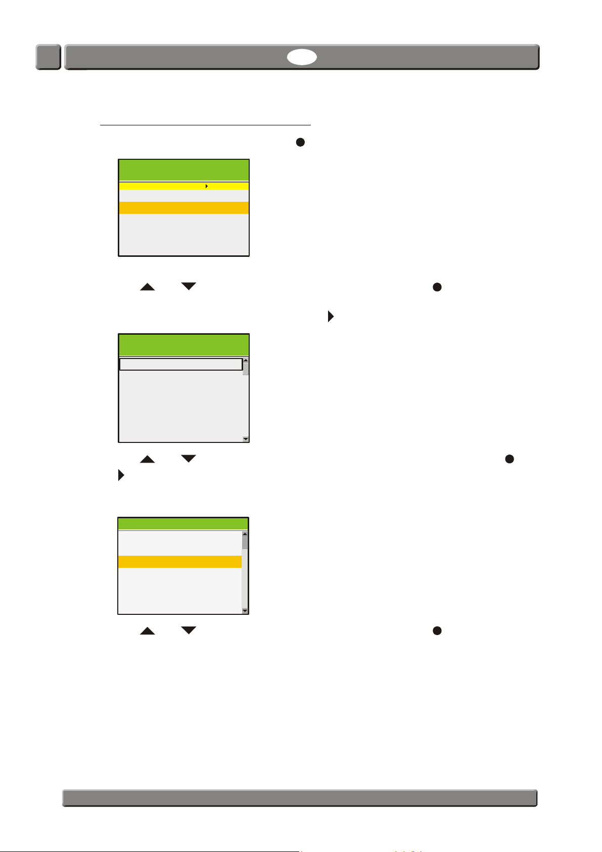
1. From the measuring screen press the key to bring up the Last used products screen.
Last us e d pr oducts
Total no. of products: 10
7: Meat mix 400gr.
This screen holds a list of the recently used products.
2. Use and keys to select the appropriate product then press to confirm and
return to the measuring screen.
If the required product is not listed press the key to bring up the Find products screen.
Find products
Total no. of products: 10
All products. Number order
All products. Last used order
3. Use and keys to select the appropriate product search method then press or
key to confirm.
4. Selecting one of the All products.... methods brings up a list of all the products sorted in
the order as selected (ex. Number order).
Matching products: 10
4:
Short Manual
Meat Mix 400gr.
47:
5. Use and keys to select the appropriate product then press to confirm and
return to the measuring screen.
PBI-300042-B 10/2010 COPYRIGHT © PBI-Dansensor A/S
Page 26
CheckMate 3 EN User Guide 25
"Sausage "
AB
HI
OP
VW
OK
1:
Matching products: 2
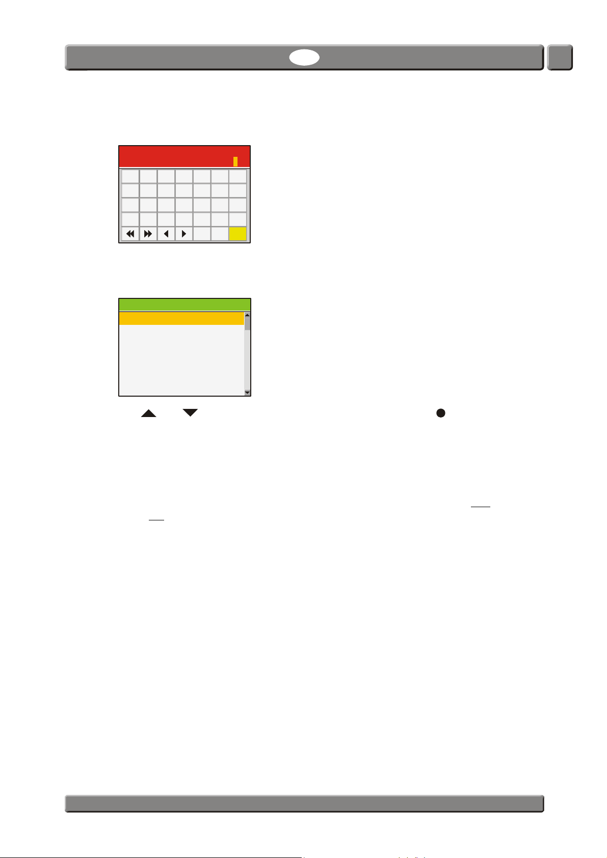
6. Selecting one of the Product.... methods (ex. Product name) brings up an appropriate
touch screen keyboard for keying in the product data.
Enter product name
CDEFG
JKLMN
QRSTU
XYZ .
Ins Del
7. Key in the product name (ex. Sausage) and confirm by pressing the OK key.
The Matching products screen will appear showing a list of all products a name starting
with Sausage.
Sausag e 100 gr.
76:
Sausag e 250 gr.
8. Use and keys to select the appropriate product then press to confirm and
return to the measuring screen.
TIP!
When selecting the Product name search method keying in only an “S” will bring up a list of
all products starting with “S”.
When selecting the Product number search method keying in “1” will bring up only
no. 1 and not
a list of all product numbers starting with “1” (ex. 1, 17, 134).
product
PBI-Dansensor A/S COPYRIGHT © PBI-300042-B 10/2010
Page 27
26 User Guide EN CheckMate 3
1
23
Data required. Press
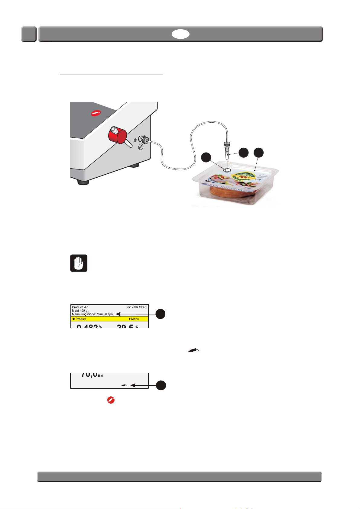
Performing a measurement
1. Make sure that the device is in Ready mode - see "Modes" on page 15.
2. Select appropriate product - see "Selecting a product for measuring" on page 24.
3. Place a septum
leak-free gas extraction and thus accurate measuring.
4. Penetrate the septum
package through the tip.
CAUTION! Do not let the needle touch the product, fluid or anything else in the
package, as this could soil the needle, hose or filter.
If this happens, the needle, hose and filter must be replaced to avoid destroying
sensors or other items inside the unit.
5. The measuring method is displayed at the top of the screen
6. If selected product requires keying in of data before measurement (see "Edit product" on
page 33 for details) Data required. Press will be displayed in the bottom of the
measuring screen
on the product/package to be measured/analysed. This ensures
with the needle so that the gas can be sucked in from the
.
4
.
5
7. Pressing the key will bring up the appropriate touch screen keyboard for keying in of
the required data. Key in the data and confirm by pressing the OK key, which will either
bring up the next data request screen if required or return to the measurement screen
ready for measuring.
8. Now start the measurement as required - see "Measuring modes" on page 23 for details.
PBI-300042-B 10/2010 COPYRIGHT © PBI-Dansensor A/S
Page 28
CheckMate 3 EN User Guide 27
Product Menu
08/17/06 13:46
%
O
2
%
CO
2
Press to measure
2,49
72,4
Product
Menu
Warning
No
Yes
13:46
08/17/06
Note required. Press
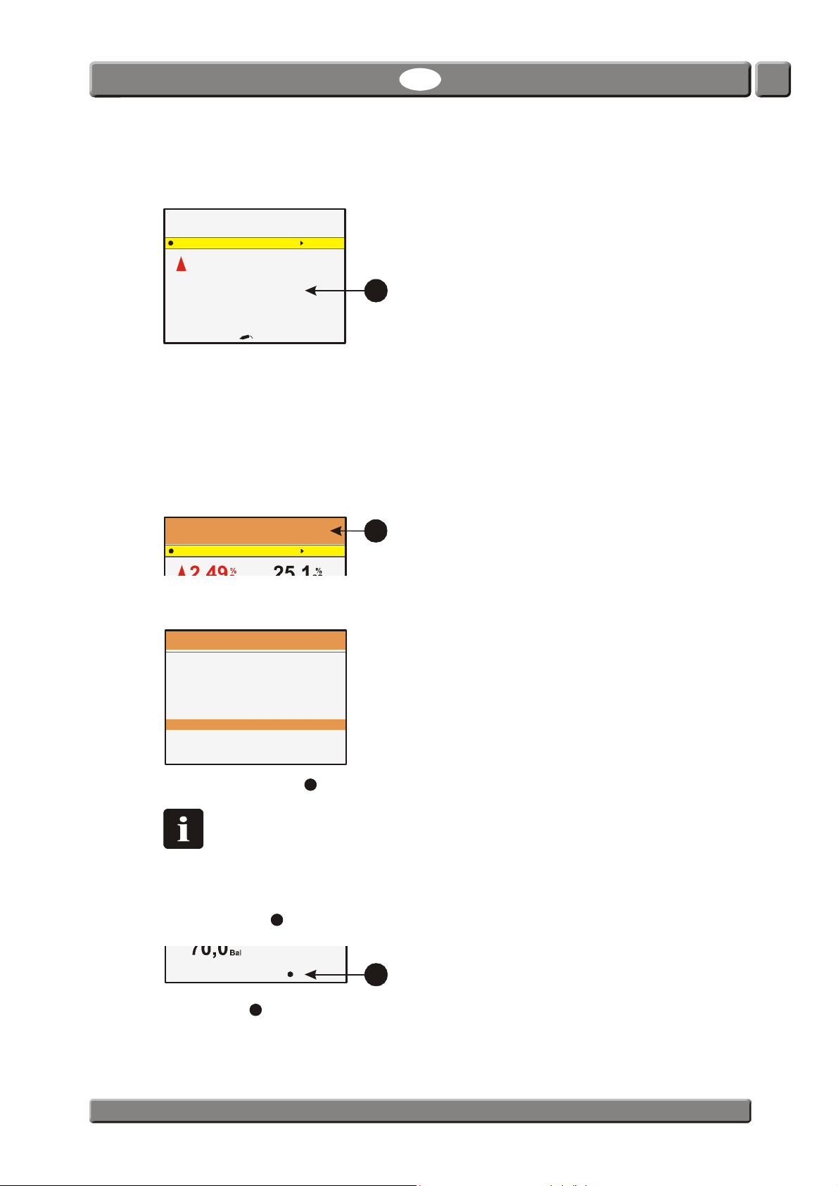
9. When measuring finishes (or in case of periodic measuring, after each measuring) the
recent result is shown on the screen
Product: 47
Meat 400 gr.
Measuring mode: Manual spot
.
25,1
6
Bal
For continuous measurements the measuring results are displayed continuously on the
screen during the measuring.
If any alarm limits have been defined, the results are shown in different colours - see
"The Measuring screen" on page 22 for details.
10. If device has been set up to use the Mark measurement as invalid function (only for
Auto spot and Manual spot measurements) the screen becomes touch sensitive for a
short while (5 sec.), while the upper section displays the text Press here to mark
measurement as invalid on an orange background
.
Press here to mark measurement as invalid
7
If you wish to invalidate the recent measurement, press anywhere on the screen. This will
bring up a confirmation screen.
Mark last measurement as invalid?
Select Yes and press to confirm.
NOTE! If you want to save measurement as invalid, make sure to confirm this
before entering any notes for the measurements if required (see item 11).
Otherwise measurement will automatically be saved as valid.
11. If selected product requires keying in of notes after the measurement (only for Auto spot
and Manual spot measurements) (see "Edit product" on page 33 for details) Note
required. Press will be displayed in the bottom of the measuring screen
.
PBI-Dansensor A/S COPYRIGHT © PBI-300042-B 10/2010
8
12.Pressing the key will bring up the appropriate touch screen keyboard for keying in of
the required note data. Key in the data and confirm by pressing the OK key to return to
the measurement screen ready for another measuring.
Page 29
28 User Guide EN CheckMate 3
3
9
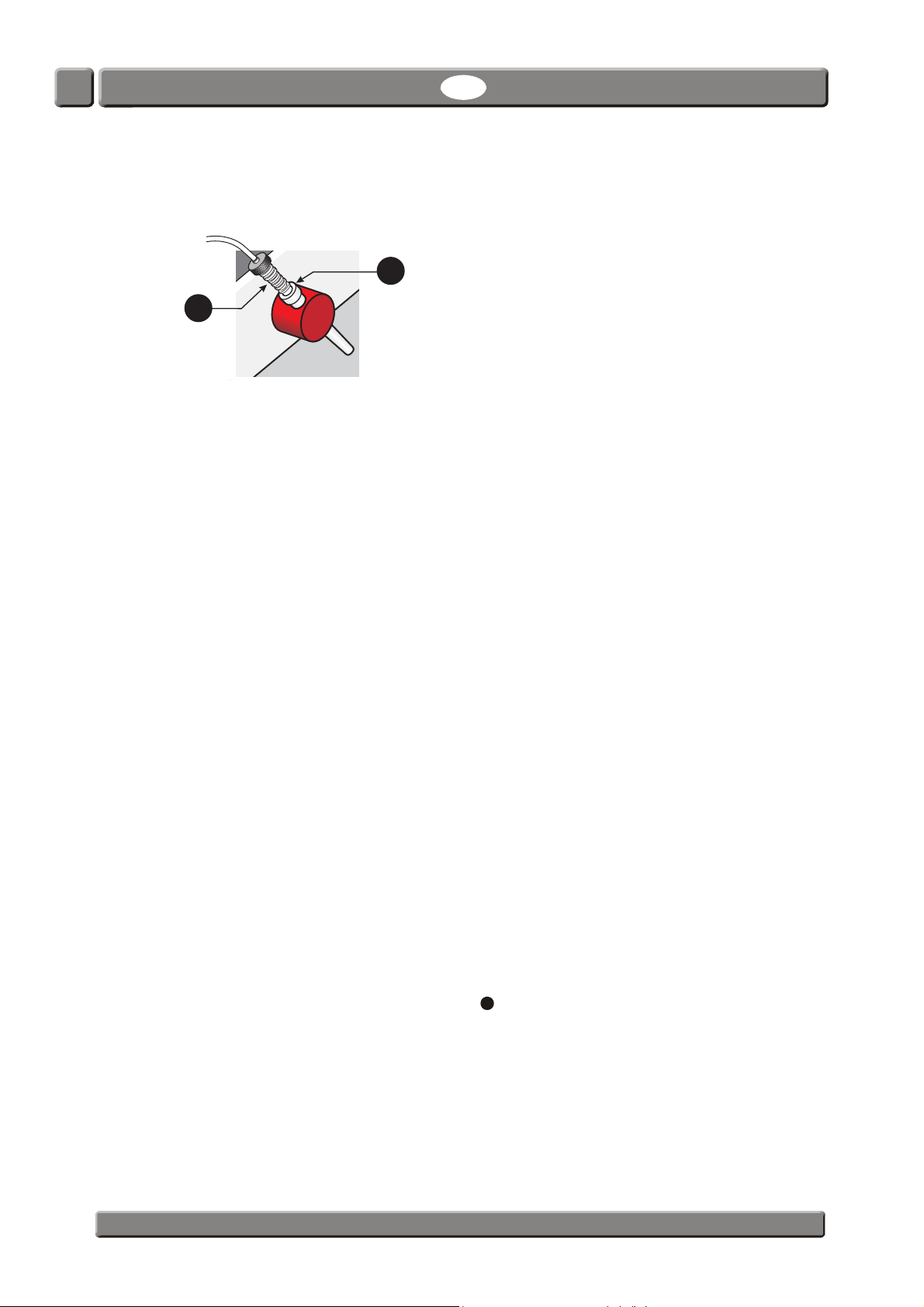
13. When finished the needle should be removed from the product package and placed
in the needle holder
on the side of device.
Daily Shut-down
At the end of the working day you have various options to shut the device down:
Switch device off Simply switch off the main switch on the backside of
the device.
Set the device to Standby mode Select Standby from the Main menu.
The device switches into Standby mode.
If a time has been set for Sleep mode in “General
setup” (see side 37) the device will automatically
switch from Standby mode to Sleep mode when set
time is reached.
Set the device to Sleep mode Select Sleep from the Main menu.
The device switches into Sleep mode.
For a detailed description of the various modes - see "Modes" on page 15.
Error messages
Four types of error messages may occur in CheckMate 3:
• Information
• Warnings
• System error
• System failure
In case of an error an error number and an error message for identification of the error is
displayed.
The error must be acknowledged by pressing .
The error number may be reported to a Service Technician to correct any errors.
A list of the most recent errors is available from the Diagnostics menu - see "Diagnostic
menu" on page 36 for details.
PBI-300042-B 10/2010 COPYRIGHT © PBI-Dansensor A/S
Page 30
CheckMate 3 EN User Guide 29
2
1
3
Cleaning and Maintenance
General
Performing cleaning and maintenance regularly reduces the chances of equipment failure.
CAUTION! Personnel performing any maintenance or cleaning must familiarize
themselves with the "Safety Instructions" on page 9 before attempting any of
these procedures.
Cleaning
All of the device’s surfaces should only be cleaned using a mild soap solution and a wrung
cloth.
CAUTION! Never use hard tools or abrasive materials when cleaning any part of the
device.
WARNING! Never use cleaning agents containing chlorinated solvents or acetic or
phosphoric acid. These constitute a health hazard and could damage the
instrument.
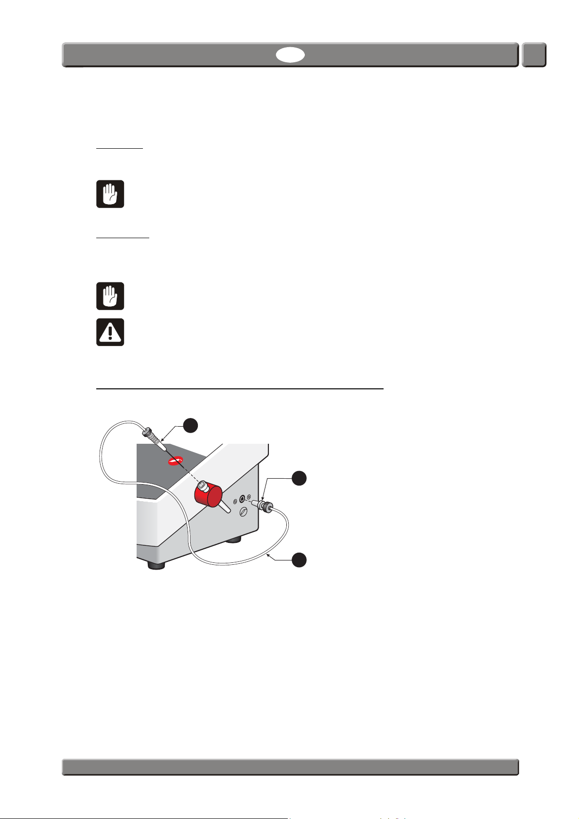
Replacing measuring gas hose, filter and needle
During use of the device dust will over time be sucked through the measuring gas system.
The measuring gas filter
environment in which the device is used.
The needle
fluid from the packaging from which the measurement is taken. If this happens, it will be
necessary to replace both the needle and the filter.
may sometimes touch the product being measured or the needle may suck
will therefore have to be replaced regularly depending on the
If there is any dirt or fluid in the measuring gas hose
using dry compressed air.
All of the parts can be ordered (and replaced) separately or as a complete kit.
See "Consumable parts and options" on page 54.
PBI-Dansensor A/S COPYRIGHT © PBI-300042-B 10/2010
, it should be replaced or cleaned
Page 31
30 User Guide EN CheckMate 3
1
3
4
2
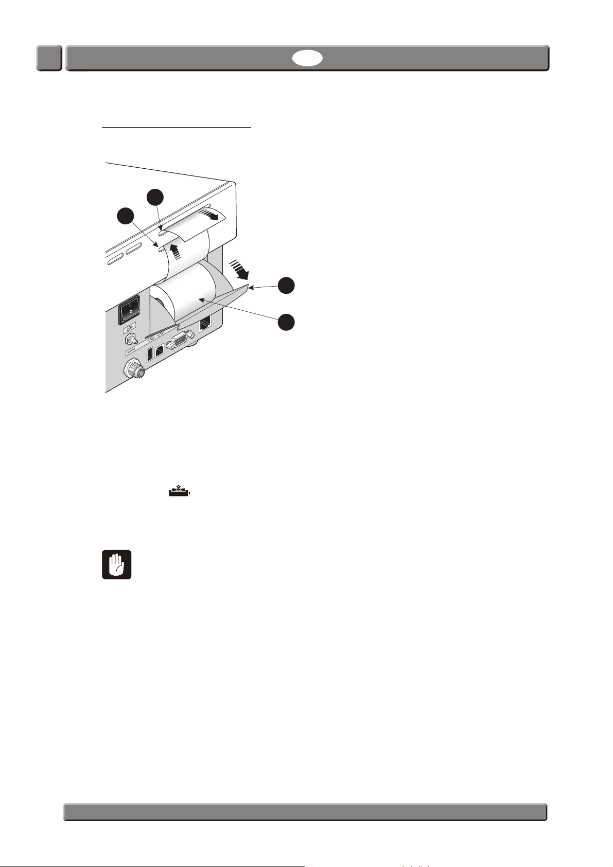
Replacing printer paper
(Only models with printer)
To replace printer paper roll do the following:
1. Open the paper roll tray
2. Place new paper roll
the printer catches it.
3. Press the key a couple of times until paper is led out through the upper paper slot
by pulling it outwards, then remove the empty paper roll.
in the tray and lead the paper into the lower paper slot until
.
4. Close paper tray
CAUTION! Do not touch the paper tear-off mechanism located at the top of the
upper paper slot
.
as there is a risk of cutting your fingers.
PBI-300042-B 10/2010 COPYRIGHT © PBI-Dansensor A/S
Page 32
CheckMate 3 EN User Guide 31
Meat 400 gr.
Product Menu
08/17/06 13:46
%
O
2
Bal
%
CO
2
Press to measure
0,482 29,5
70,0
08/17/06
General setup
Calibra tion
Sta ndby
Sleep
Language
Access level
3. Menus and Settings
General
When device is switched on (after power off) it is locked in User access level. In User access
level the operator has access to a limited number of functions only and is not allowed to
perform parameter set-up.
To obtain full access you have to change the device to Supervisor access level.
See "Access level" on page 43 for details.
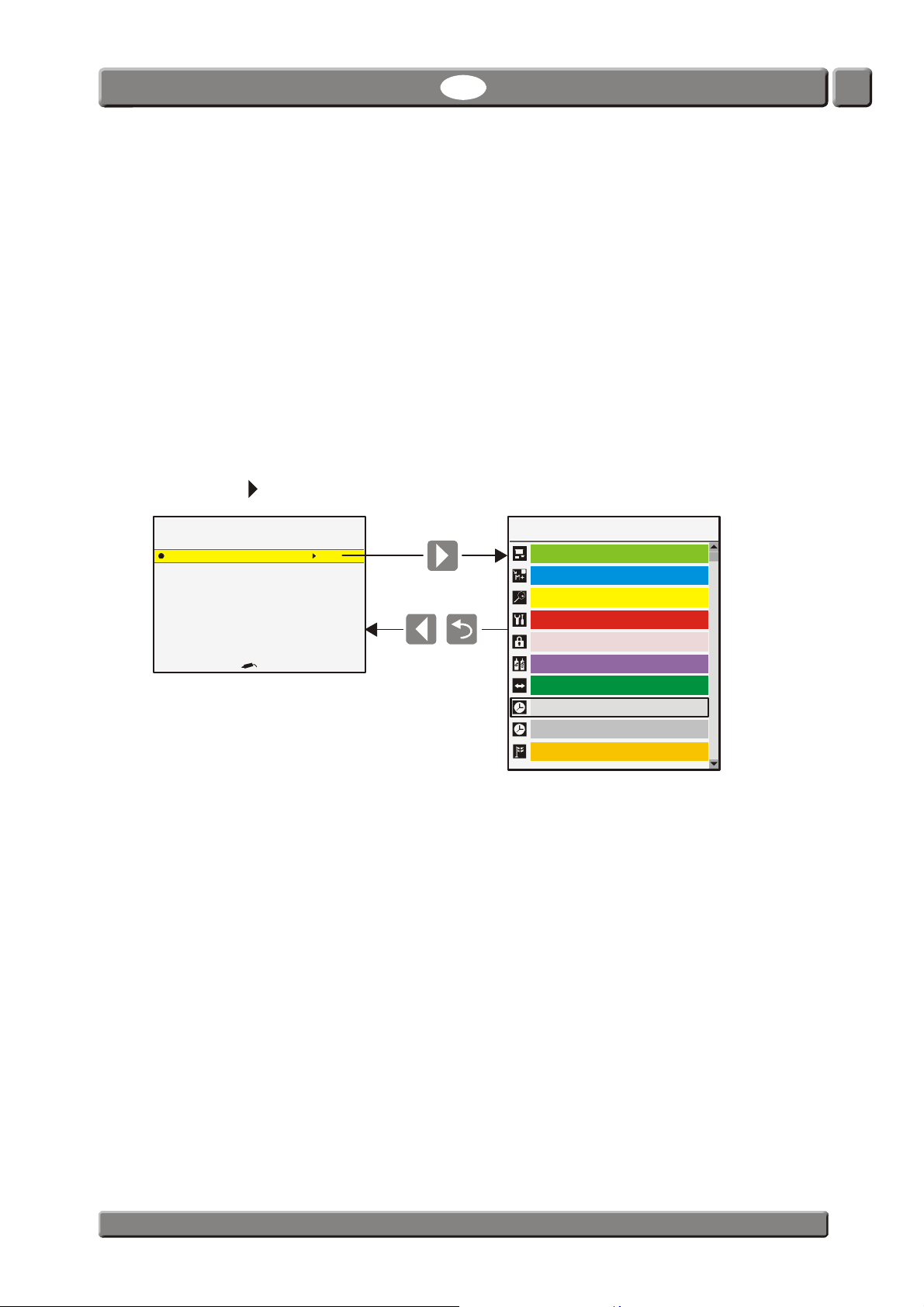
Main menu
Pressing the key from the measuring screen brings up the Main menu
From the Main menu you can select the following submenus:
Menu items marked with an asterisk (*) are not available in User access level.
©Product menu* Create, edit and delete products.
Data log View logged data for currently selected product.
´ Diagnostic menu Display device’s internal parameters and error diagnostics.
General setup* Setting of various device parameters.
§ Access level Selection of access level for User, Supervisor and Service.
Calibration* Calibration of sensors - for Service Technicians only.
Product: 47
Measuring mode: Manual spot
Main menu
Product menu
Data log
Diagnost i c menu
Export / Import
Display and delete logged product data.
See "Product menu" on page 33 for details.
See "Data log" on page 36 for details.
See "Diagnostic menu" on page 36 for details.
See "General setup" on page 37 for details.
See"Access level" on page 43 for details.
13:46
PBI-Dansensor A/S COPYRIGHT © PBI-300042-B 10/2010
Page 33

32 User Guide EN CheckMate 3
Export / Import* Export of product log data, export/import of products, users and
device settings.
Requires connection of a USB memory key.
See "Export/Import" on page 47 for details.
Standby Log off and switch the device into Standby mode.
See "Standby" on page 47 for details.
Sleep Log off and switch the device into Sleep mode.
See "Sleep" on page 48 for details.
Language Change language of screens and menus.
See "Language" on page 48 for details.
PBI-300042-B 10/2010 COPYRIGHT © PBI-Dansensor A/S
Page 34
CheckMate 3 EN User Guide 33
Product menu
Total no. of products: 10
Edit product
New product
Copy product
Delete product
View collected data
Delete collected data
Delete all collected data
47:
7:
99:
1:
Meat Mix 1000gr.
Junk food
Meat 400gr.
Meat Mix 400gr.
Food
Sausage
Product menu
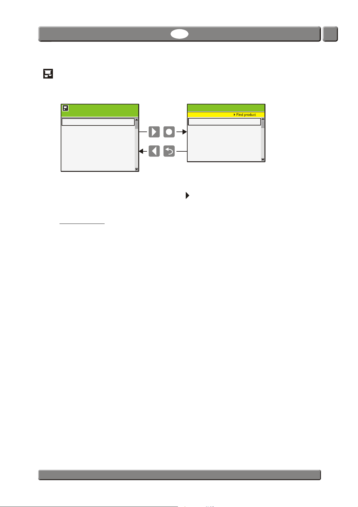
Selecting Product menu from the Main menu will display a menu with available product
options.
Products : 10
25:
9999:
Selecting a function will display all products in the last used order. To find a product by
sorting all products in a different order press key.
Up to 1000 different products can be stored.
Edit product
This function allows you to edit the set-up of a product. The following parameters can be set
for each product:
Product name A unique product name of up to 40 characters
Product number A random product number (0 to 999999)
Barcode ID Unique product barcode. Used to perform a quick product
selection using the barcode reader (option)
Measure mode Select between the following 4 measuring modes:
Manual spot, Auto spot, Intermittent and Continuous.
See "Measuring modes" on page 23 for details.
For the Manual spot and Intermittent modes you must set
the required sample and delay times.
Display gasses Select whether or not a value should be displayed on the
measuring screen. The number of potential gasses depends
on the CheckMate 3 type and the sensors installed. Up to 4
gasses/values can be displayed on the measuring screen.
Concentration alarms 1 - 6 Setting of the alarms. You have the following options for each
alarm:
- Inactive (Off), High alarm or Low alarm
- The limit value that must be exceeded to activate the
alarm.
- The gas/value to be used for the particular alarm.
PBI-Dansensor A/S COPYRIGHT © PBI-300042-B 10/2010
continues...
Page 35
34 User Guide EN CheckMate 3
Customer fields Select whether or not keying in of customer data before and/
or after the measurement is required.
Note data must be entered after the measurement if
required. In these cases Note required. Press will be
displayed in the bottom of the measuring screen.
You have the following options for Note settings:
(Only applies to products set to Auto spot or Manual spot
measurement)
Off Keying in of data will not be required.
If alarm Keying in of data will be required if
measurement raises any type of alarm.
If no alarm Keying in of data will be required if
measurement raises no alarms.
Always Keying in of data will be required after
each measurement.
Free Keying in of data is possible, but not
required.
In these cases Press to enter note will
be displayed in the bottom of the
measuring screen.
Press key to enter the data or press
key to skip.
Custom field 1-5 data must be entered before start of the
measurement if required. In these cases Data required.
Press will be displayed in the bottom of the measuring
screen.
You have the following options for each of the Custom field
1-5 settings:
Off Keying in of data will not be required.
Always Keying in of data will be required before
each measurement.
Once Keying in of data will be required only
before the first of a series of
measurements for the same product.
Each of the Custom fields can be named to show the
operator the type of data to be entered.
See "Custom fields setup ..." on page 41 for details.
New product
This function creates a new product with standard set-ups. The values can then be adjusted
to the desired product (see "Edit product" on page 33).
PBI-300042-B 10/2010 COPYRIGHT © PBI-Dansensor A/S
Page 36

CheckMate 3 EN User Guide 35
Copy product
This function copies an existing product to a new product. The values can then be adjusted
to the desired product (see "Edit product" on page 33).
This function can be used to create a new product that is similar to an existing product.
Delete product
Unused products can be deleted. When deleting a product both the product and the
product’s logged data are deleted.
The action must be confirmed before deletion is performed.
View collected data
This function enables the operator to display logged data for any of the existing products.
(Selecting Data log from the main menu displays logged data for the currently selected
product only.)
Delete collected data
Use function to delete the logged data for an existing product.
The action must be confirmed before the data is deleted.
Delete all collected data
Use function to delete the logged data for all products.
The action must be confirmed before the data is deleted.
PBI-Dansensor A/S COPYRIGHT © PBI-300042-B 10/2010
Page 37
36 User Guide EN CheckMate 3
Product Meat: Mix 400gr.
Data collection: 21
Sample time %CO2 Bal mbar
Data log
13:46
08/17/06
28/8/ 05 16:46:18 XX.X Low XX.X XXX. X
28/8/ 05 16:46:10 XX.X XX.X XXX.X
28/8/ 05 16:45:59 XX.X XX.X XXX.X
28/8/ 05 16:45:51 XX.X Low XX.X XXX. X
28/8/ 05 16:45:45 XX.X XX.X XXX.X
28/8/ 05 16:45:37 XX.X Low XX.X XXX. X
Printing
08/17/06
Data collection s
Statistics
Diagnostic
13:46
08/17/06
Atmospheric pressur e
XXXX,X mbar
Sample h ose XXX,X mbar
Packag e pressure
XXX,X mbar
O sensor (EC)
2
Diagnostic
28/8/2005 16:45 Er. xxxx
Device temperatu re to high
26/8/ 200 5 1 1:45 Er . xxxx
6/8/2005 10:45 Er. xxxx
xxxxxx
6/8/2005 10:44 Er. xxxx
xxxxxx
6/8/2005 10:35 Er. xxxx
xx xxxxxx xx xx xx xxxxxx
6/8/2005 10:01 Er. xxxx
Data log
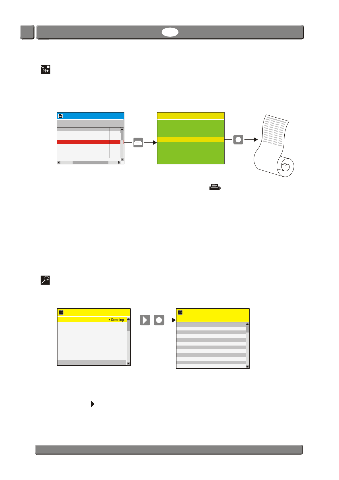
Selecting Data log from the Main menu will display a screen with a list of all the logged data
for the currently selected product.
Measuments which have been interrupted or marked as invalid are displayed on a red
background.
13:46
From here the logged data can be printed by pressing the key (devices with built-in
printer only).
Logged data can be exported (see "Export/Import" on page 47 for details) or deleted (see
"Product menu" on page 33 for details).
Data log memory full
If data log memory is full an error will occur (Error code: 2679, No free space on flash).
In this case you must empty data log by using the functions for deleting of data collections see "Product menu" on page 33 for details.
Please note that new measurements will not be logged until current data logs have been
deleted.
Diagnostic menu
Selecting Diagnostic menu from the Main menu will display a screen showing the internal
parameters of the device.
13:46
Error log
Current user USER1
Device temperature XX, X °C
O2 sensor temperature t o high
These are values such as current user, device’s internal temperature, the pressure in the
sensors, the sensor’s conditions, serial numbers for main components, day/hour counters,
time to calibration, and software versions, etc.
08/17/06
Pressing the key brings up an Error log screen with a list of all errors for the selected
product.
PBI-300042-B 10/2010 COPYRIGHT © PBI-Dansensor A/S
The parameters can only be read and not changed.
Page 38
CheckMate 3 EN User Guide 37
Data log setup ...
Network setup ...
User setup ...
Back light 1
Contrast 7
Brightness 6
Measure dela y 1,0 sec
General setup
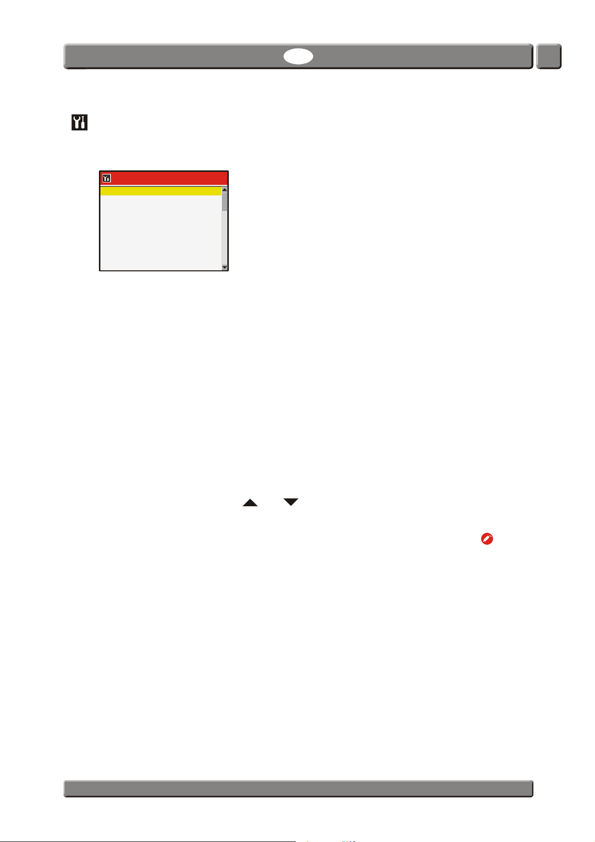
Selecting General setup from the Main menu will display a menu with available set-up
parameters.
General setup
Custom fields setup ...
Menu items followed by ... brings up a submenu with available set-up parameters for the
selected item.
The General setup menu holds the following items:
Data log setup ... Opens the Data log setup screen
Network setup ... Opens the Network setup screen
Custom fields setup ... Opens the Custom fields setup screen
User setup ... Opens the User setup screen
Back light Adjust display background light (1-5)
13:46
08/17/06
See "Data log setup ..." on page 38 for details.
See "Network setup ..." on page 41 for details.
See "Custom fields setup ..." on page 41 for details.
See "User setup ..." on page 42 for details.
Contrast Adjust display contrast. (1-10)
When display shows the measuring screen you can use the
and keys to adjust screen contrast.
Brightness Adjust display brightness (1-10)
Measure delay Time before measurement starts after pressing the key.
(0.0 - 999.9 sec.)
Standby after Time before device switches into Standby mode when not in
use.
(0 = Off) (1-100,000,000 min.)
Please note that even though function is set to 0 (Off) the
device can still be forced into Standby mode by selecting
Standby from the Main menu - see "Standby" on page 47 for
details.
Sleep mode after Time before device switches into Sleep mode when not in
use.
(0 = Off) (1-100,000,000 min.)
Please note that even though function is set to 0 (Off) the
device can still be forced into Sleep mode by selecting Sleep
from the Main menu - see "Sleep" on page 48 for details.
PBI-Dansensor A/S COPYRIGHT © PBI-300042-B 10/2010
Page 39
38 User Guide EN CheckMate 3
Data log setup ...
Log alarms only No
Log interval 6 sec
Log t o in terna l memor y Yes
Print eac h measurement No
Mark measurement as invalid
Yes
Network logging setup
Network logging No
Time Setting of current time (hh:mm:ss)
Date Setting of current date (using Date format) (
± 2 days)
Date format Setting of date format (DD/MM/YY or MM/DD/YY)
Decimal separator Select whether to use “,” or “.” as decimal separator
Printer header Select header text for printouts (ex. company name).
Supervisor pin code setup Setting up the pin code required for changing from User
access level to Supervisor access level.
(See "Access level" on page 43 for details).
Data log setup ...
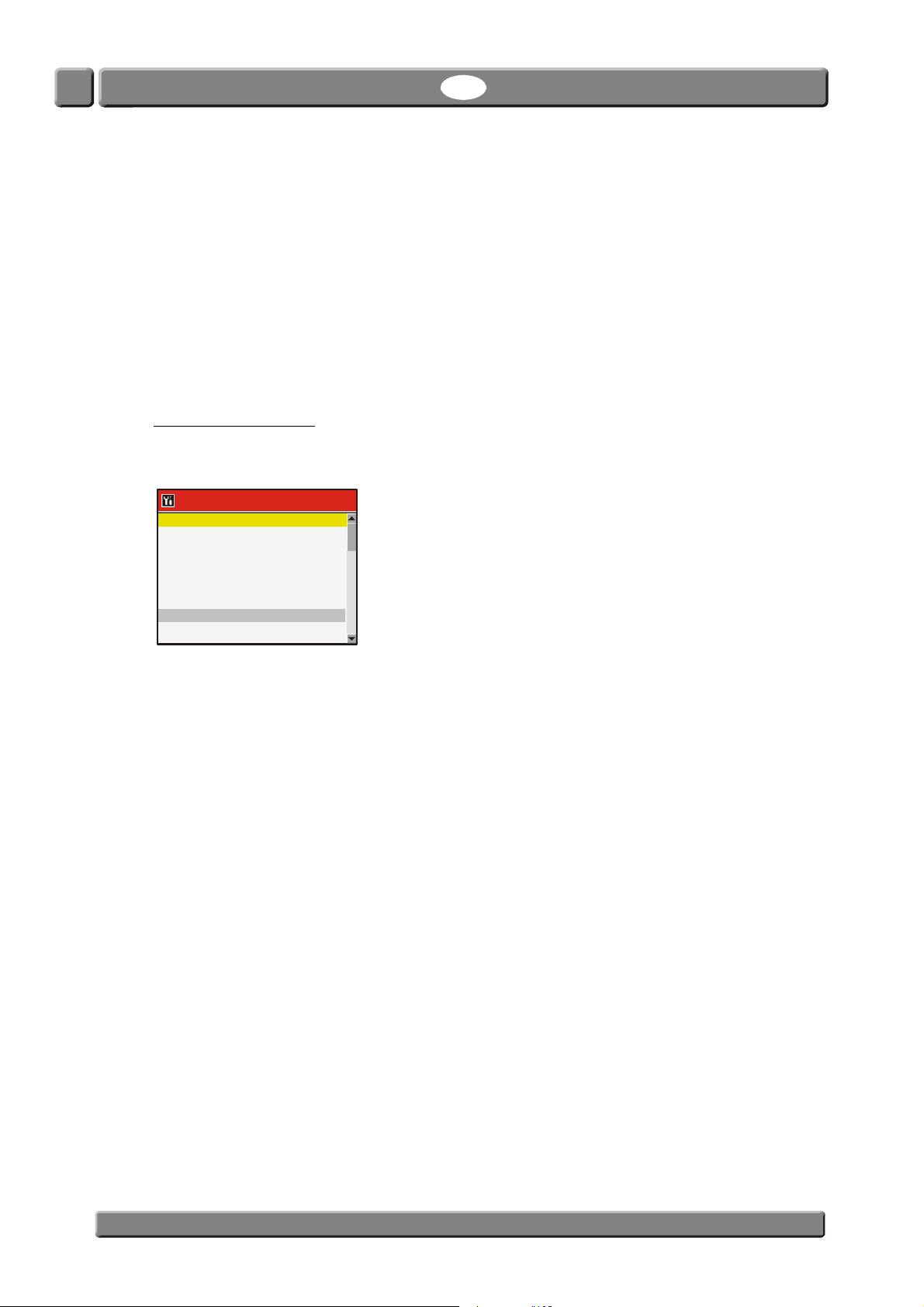
Selecting Data log setup ... from the General setup menu will display a screen showing the
data logging parameters.
13:46
08/17/06
This is where you make all settings for logging of data.
As most of the parameters are self-explanatory only items requiring for further clarification
are described below:
Log to internal memory Select whether or not log data should be saved in the
internal memory of the device to be displayed and
printed from the Data log menu (see "Data log" on
page 36).
Yes Log data is saved internally and send to
COM-port/LAN-server.
No Log data is send only to COM-port/LAN-server.
Print each measurement Yes Printer will print a header and subsequently each
logged measurement will be printed
automatically line by line
No Function deactivated
Mark measurement as invalid Yes After each measurement performed in either
Auto spot or Manual spot mode you will be
asked if you want to mark measurement as
invalid.
No Function deactivated
PBI-300042-B 10/2010 COPYRIGHT © PBI-Dansensor A/S
Page 40

CheckMate 3 EN User Guide 39
Network logging setup Network logging Select whether or not network logging is
required.
Server IP Set up an IP-address to be used for
collecting log data for each measurement
via LAN.
This requires for setting up of a Server
Port number as well.
Server Port See above.
If Server IP or Server Port or both are set to 0 the function is
deactivated and data will only be send to the COM-port.
Acknowledge Acknowledge byte can be used if a
“handshake”is required for each
measurement between device and server,
each to be set up to same value.
If value is set to 0 function is deactivated.
Function can be used together with the TCP Wedge or TCP
File from Taltech, TCP File from Fogsoft or a proprietary
setup TCP/IP server.
Data is send out in same format and setup as for the COMport.
Data out format Format Select between ASCII or UNICODE
Data out Select which parameters are required for the data output.
Selected data is always send to the device’s COM-port and if
a server has been set up in Network logging (see above)
data is send here as well.
When using RS-232 COM port setting must be: 57600,N,8,1
Serial data dump specification
Each measurement is on one line terminated with a Carriage Return + Line Feed characters
(ASCII 0x0D, 0x0A).
The line consists of data separated by semicolons (";"). Last parameter is also followed by a
semicolon.
In the "Data log setup...” (see side 38) it can be selected whether the output format should
be ASCII or UNICODE.
When set to ASCII some international characters might come out as wrong ASCII characters.
The table on the next page shows which data is presented and the order of the data.
PBI-Dansensor A/S COPYRIGHT © PBI-300042-B 10/2010
Page 41

40 User Guide EN CheckMate 3
Column
Start
pos.*
Length ** Type Description Note
1 1 8 Numeric O2 [%] Fixed decimal point, eg. "020.9465"
2 10 8 Numeric CO2 [%] Fixed decimal point, eg. "020.9465"
3 19 8 Numeric Balance [%] Fixed decimal point, eg. "020.9465"
4 28 8 Numeric CO [%] Fixed decimal point, eg. "020.9465"
5 37 1 Numeric O2 alarm [0=No alarm 1=High Alarm 2=Low Alarm]
6 39 1 Numeric CO2 alarm [0=No alarm 1=High Alarm 2=Low Alarm]
7 41 1 Numeric CO alarm [0=No alarm 1=High Alarm 2=Low Alarm]
8 43 6 Numeric Product number [Integer] No decimal point (e.g. "000032")
9 50 8 Text Date [MM/DD/YY] / [DD/MM/YY] Variable according to set-up
10 59 8 Text Time [HH:MM:SS]
11 68 40 Text Product name [Text] Left alligned
12 109 40 Text Product barcode [Text]
13 150 24 Text CheckMate II S/N [Text]
14 175 40 Text User ID [Text]
15 216 37 Text User field 1 [Text]
16 254 37 Text User field 2 [Text]
17 292 37 Text User field 3 [Text]
18 330 37 Text User field 4 [Text]
19 368 37 Text User field 5 [Text]
20 406 100 Text Note [Text]
21 507 14 Text SW version [Text]
22 522 1 Numeric Measure mode
[0=Continuous, 1=manual spot, 2=auto spot 3=intermitted]
23 524 6 Numeric Sample time [seconds] Fixed decimal point plus sign, eg. "+005.0"
24 531 6 Numeric Measure delay at intermitted [minutes] No decimal point
25 538 1 Numeric Alarm 1 type [0=Off, 1=high, 2=Low]
26 540 1 Numeric Alarm 1 gas [0=O2, 1=CO2, 2=CO]
27 542 8 Numeric Alarm 1 concentration [%] Fixed decimal point, eg. "020.9465"
28 551 1 Numeric Alarm 2 type[0=Off, 1=high, 2=Low]
29 553 1 Numeric Alarm 2 gas [0=O2, 1=CO2, 2=CO]
30 555 8 Numeric Alarm 2 concentration [%] Fixed decimal point, eg. "020.9465"
31 564 1 Numeric Alarm 3 type[0=Off, 1=high, 2=Low]
32 566 1 Numeric Alarm 3 gas [0=O2, 1=CO2, 2=CO]
33 568 8 Numeric Alarm 3 concentration [%] Fixed decimal point, eg. "020.9465"
34 577 1 Numeric Alarm 4 type[0=Off, 1=high, 2=Low]
35 579 1 Numeric Alarm 4 gas [0=O2, 1=CO2, 2=CO]
36 581 8 Numeric Alarm 4 concentration [%] Fixed decimal point, eg. "020.9465"
37 590 1 Numeric Alarm 5 type [0=Off, 1=high, 2=Low]
38 592 1 Numeric Alarm 5 gas [0=O2, 1=CO2, 2=CO]
39 594 8 Numeric Alarm 5 concentration [%] Fixed decimal point, eg. "020.9465"
40 603 1 Numeric Alarm 6 type[0=Off, 1=high, 2=Low]
41 605 1 Numeric Alarm 6 gas [0=O2, 1=CO2, 2=CO]
42 607 8 Numeric Alarm 6 concentration [%] Fixed decimal point, eg. "020.9465"
43 616 1 Numeric Note [0=Off, 1=At alarm, 2=At no alarm, 3= Always, 4=Always]
44 618 1 Numeric User field 1 required [0=no, 1=Always, 2=Once]
45 620 1 Numeric User field 2 required [0=no, 1=Always, 2=Once]
46 622 1 Numeric User field 3 required [0=no, 1=Always, 2=Once]
47 624 1 Numeric User field 4 required [0=no, 1=Always, 2=Once]
48 626 1 Numeric User field 5 required [0=no, 1=Always, 2=Once]
49 628 6 Numeric Device temperature [°C] Signed value and fixed point
(eg. "+023.0" or "-003.2")
50 635 6 Numeric Atmospheric pressure [mbar] No decimal point
51 642 1 Numeric Invalid measurement [0=No, 1=Yes]
Total: 644 Chars in ASCII (x4 in UNICODE) +CRLF
* Only when all elements are selected and format is ASCII.
** Length: Fixed length. When unicode length must be multiplied by 4.
Fixed decimal placement. Leading zero in numbers. Gas concentrations are always in % buth with ppm resolusion (regardless of accuracy) e.g. "020.9465"
Example:
000,8395;000,3200;098,8405;000,0000;0;0;0;000002;27/02/08;16:43:39;Product 2;
Serial data dump specification
PBI-300042-B 10/2010 COPYRIGHT © PBI-Dansensor A/S
Page 42
CheckMate 3 EN User Guide 41
IP-address XX.XX.XX.XX
Subnet mask XXX.XXX.XXX.X
Default gateway XXX.XX.X.X
Custom field 1:
Custom field 2:
Custom field 3:
Custom field 4:
Custom field 5:
Network setup ...
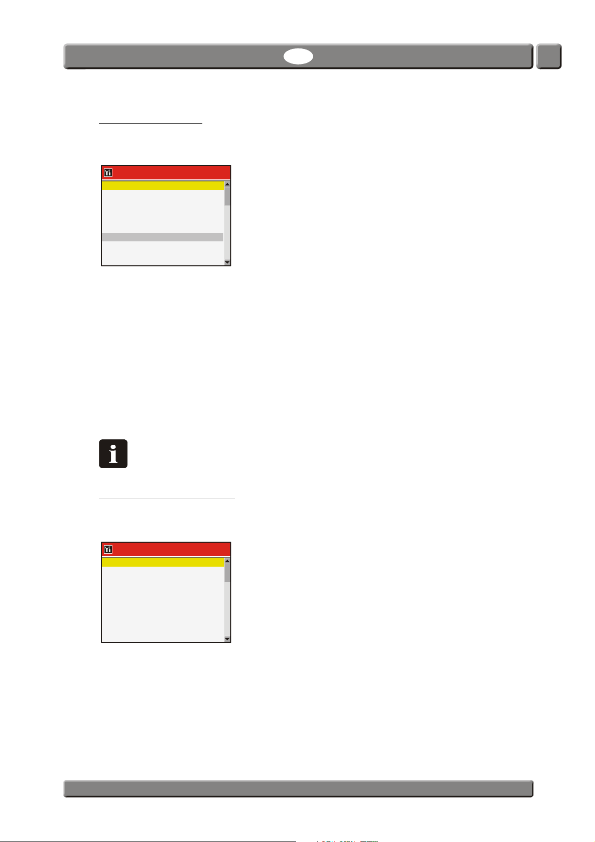
Selecting Network setup ... from the General setup menu will display a screen showing the
network set-up parameters.
Network setup ...
DHCP No
13:46
08/17/06
This is where you make the device’s network (LAN) settings.
It is possible to choose between a fixed (static) IP-address or a DHCP (dynamic) IP-address,
where the device’s network settings are assigned from a DHCP server on the network.
Default setting is DHCP (Yes).
Setting DHCP to No brings up following parameters for setting up a static IP-address:
IP-address
Subnet mask
Default gateway
These parameters have to be set up to the existing network.
NOTE! Always consult your network administrator before making network settings,
as incorrect settings can result in reduced or no network activity.
Custom fields setup ...
Selecting Custom fields setup ... from the General setup menu will display a screen showing
the list of available Custom fields (1-5).
Custom fields
This is where you key in the text (max. 40 characters) which will be displayed as the header
on each of the appearing Custom field data input windows when used.
PBI-Dansensor A/S COPYRIGHT © PBI-300042-B 10/2010
13:46
08/17/06
Page 43
42 User Guide EN CheckMate 3
Show users
Edit user
New user
User log in: Yes
Log in with ID: Yes
User setup ...
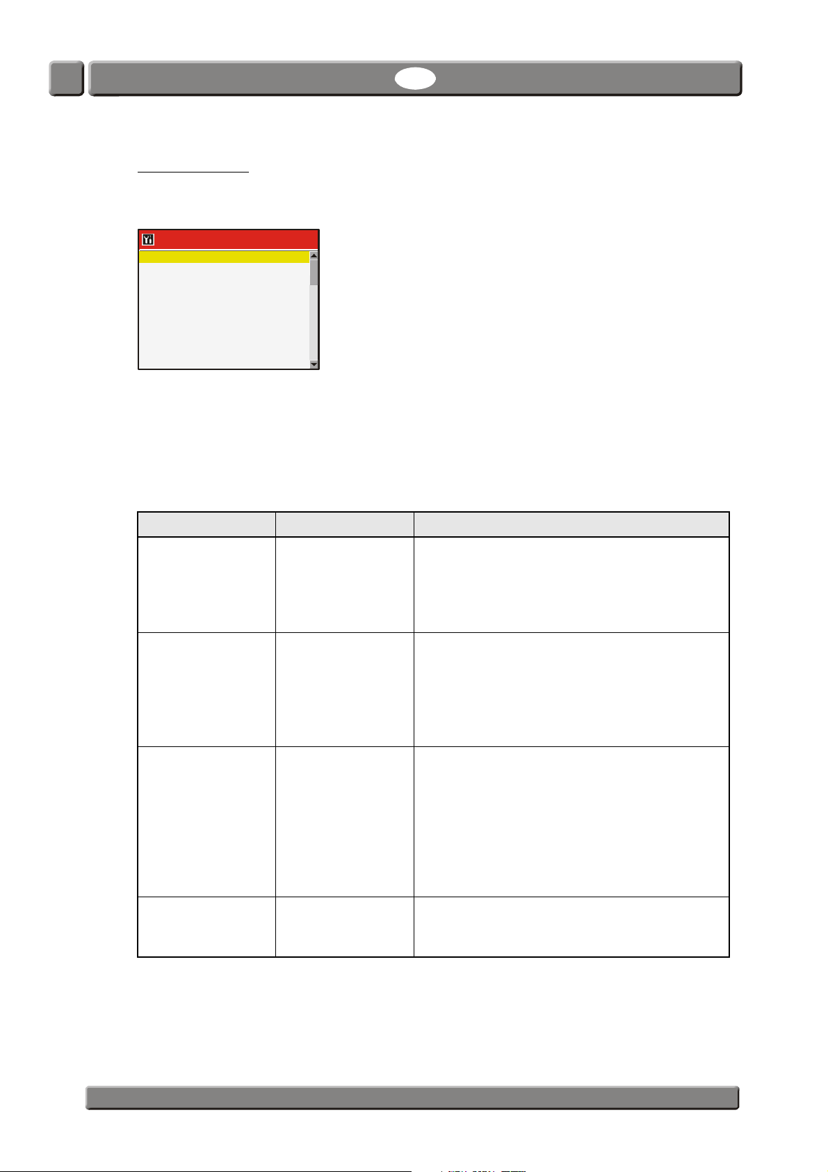
Selecting User setup ... from the General setup menu will display a screen showing the User
setup parameters.
User setup ...
Delete user
13:46
08/17/06
From here the user database is maintained. You can see a list of existing users, edit the
settings for an existing user, create new users or delete users.
Users are created with a unique User name (max. 20 characters) and a unique login User ID
(max. 40 characters).
The set-up of the login function is defined according to table below:
User log in Log in with ID Function
No No No login required (default setting)
At start-up the device will automatically run the
self-test and warm-up period and when finished
it changes to show the measuring screen and
will be ready for measuring.
Yes No User login required
At start-up you are prompted to select user from
appearing list and when done the device will
run the self-test and warm-up period and when
finished it changes to show the measuring
screen and will be ready for measuring.
Yes Yes Login with User ID required
At start-up you are prompted to enter User ID
either by keying it in from the touch screen keyboard or by using a barcode scanner (option).
When done the device will run the self-test and
warm-up period and when finished it changes to
show the measuring screen and will be ready
for measuring.
No Yes Not possible!
Setting User login to No will automatically
change Login with ID to No.
PBI-300042-B 10/2010 COPYRIGHT © PBI-Dansensor A/S
Page 44
CheckMate 3 EN User Guide 43
Enter pincode: ****
13:46
08/17/06
Access level
When device is switched on (after power off) it is locked in User access level. In User access
level you have only access to a limited number of functions and is not allowed to perform
parameter set-up.
To obtain full access you have to change the device to Supervisor access level.
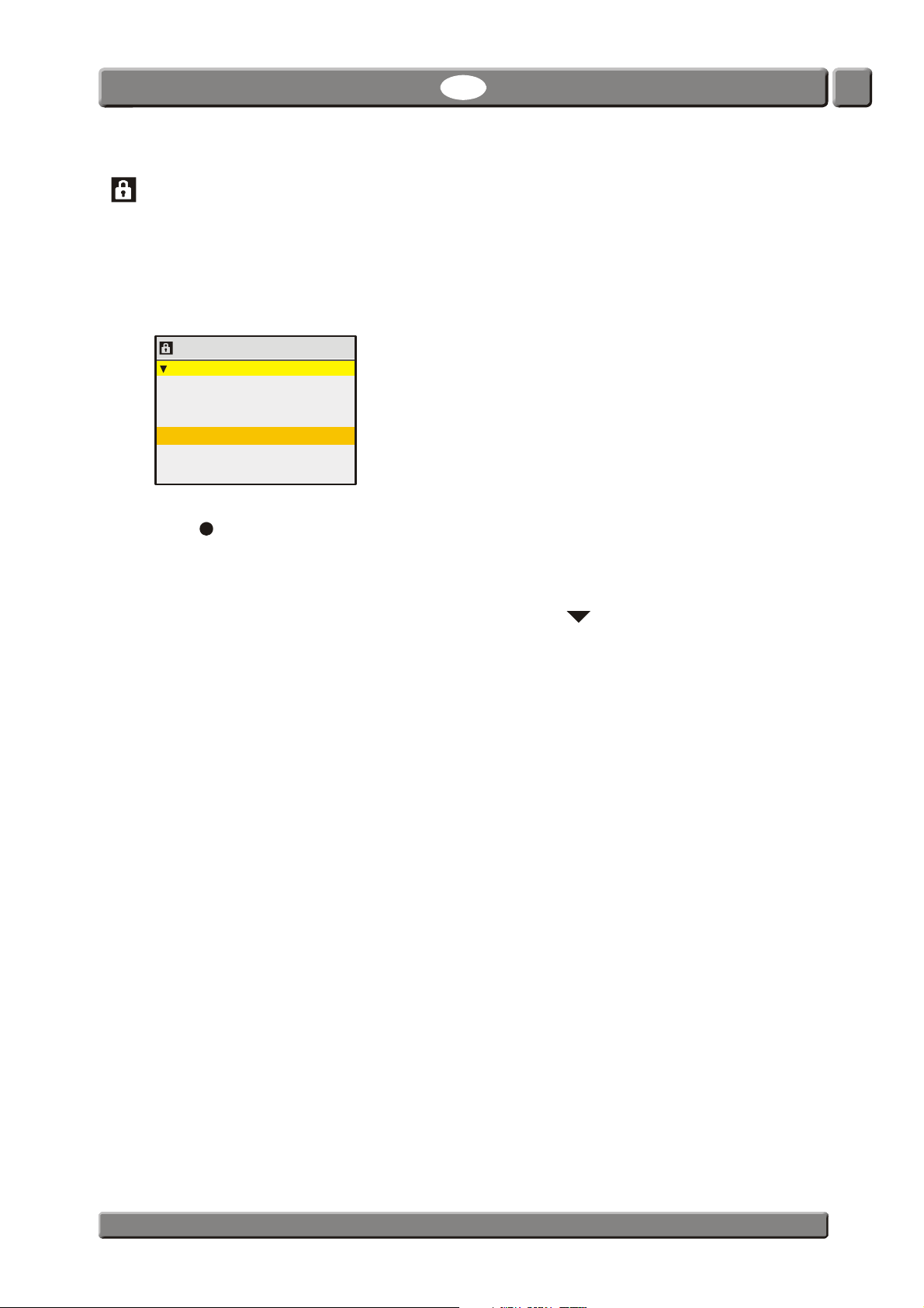
To do so select Access level from the Main menu menu to display the Access level screen.
Access level
lock instrument in user level
Current access level: Supervisor
Press key to open a touch screen keyboard and enter the pin code for Supervisor access
level. From the factory the pin code is set to “0”.
The Supervisor pin code can be changed to one of your own selection - see "General setup"
on page 37 for details.
To return the device to User level access either press the key from the Access level
screen or power the device off and on.
PBI-Dansensor A/S COPYRIGHT © PBI-300042-B 10/2010
Page 45
44 User Guide EN CheckMate 3
Product Menu
08/17/06 13:46
%
O
2
%
CO
2
Press to measure
0,482 29,5
70,0
Acces s level
lock instrument in user level
Current access level: User
Enter pincode: ****
13:46
08/17/06
Ent er ac ce s s pi n c o de :
*
123+/456Del
789CA
000000OK
Calibration
NOTE! Apart from the below described “Offset (20,9%) calibration” all calibration
procedures must be carried out by Service Technicians only, as calibration
requires for special skills and the access to certified calibration gasses.
Invalid calibration compromises measurement results.
Offset (20,9%) calibration
NOTE! Only applies to O2 EC (Electro-chemical) sensors.
Follow procedure below to perform the calibration:
1. From the measuring screen push the key.
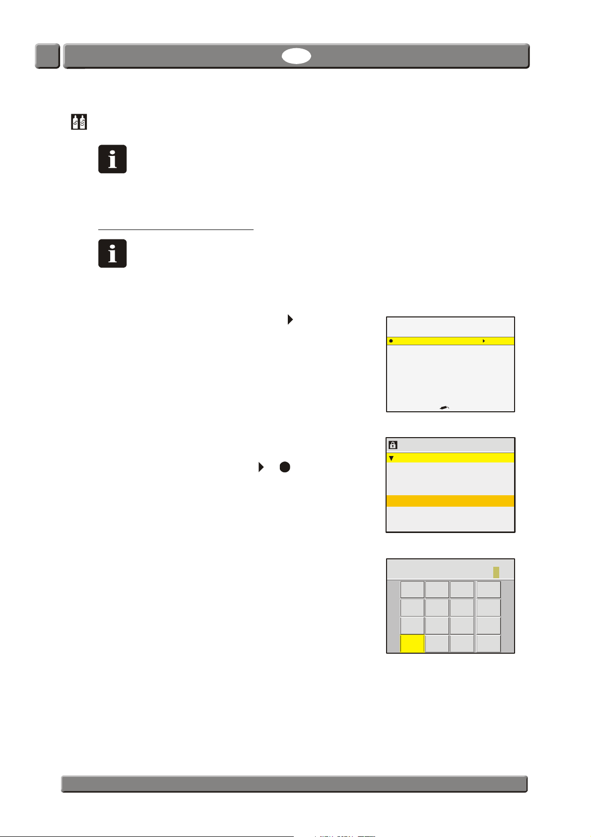
2. If you are not already in Supervisor mode select Access
level from the main menu.
3. To enter the pin code push the or key.
4. The standard code from the factory is "0", but it may
have been changed.
Use the appearing touch-screen keyboard to enter the
appropriate code and push "OK".
Product: 47
Meat 400 gr.
Measuring mode: Manual spot
Bal
PBI-300042-B 10/2010 COPYRIGHT © PBI-Dansensor A/S
Page 46
CheckMate 3 EN User Guide 45
13:46
08/17/06
Main menu
Dat a lo g
Product menu
Diagnost ic menu
Gener al se t u p
Calibration
Access level
13:46
08/17/06
Calibrate
%mVmbardate
20,9460 18,208 1031,9 05/08/06
CO sensor (100%)
%mbardate
100,00 0,533 1034,0 05/08/06
60,00 0,463 1034,0 05/08/06
25,00 0,336 1034,0 05/08/06
2
2
2
2
Calibrate
Perfo rm calibration
Erase / enter calibration
13:46
08/17/06
!!! WARNING !!!
Calibration requires use of certified gases
Wrong calibration will cause invalid measurements
13:46
08/17/06
O sensor (EC)
O Response Pressure Calibration
%mVmbardate
CO sensor (100%)
CO Response Pressure Calibration
%mbardate
2
2
2
2
20,9460 XX,XXX XXXX,X XX/XX/XX
Calibrating
Select gas and press
13:46
08/17/06
XX,XXX
XX,XXX
XXX,X
%O
mV
mbar
2
20,9460
Sensor:
EMF:
Pressure:
1:
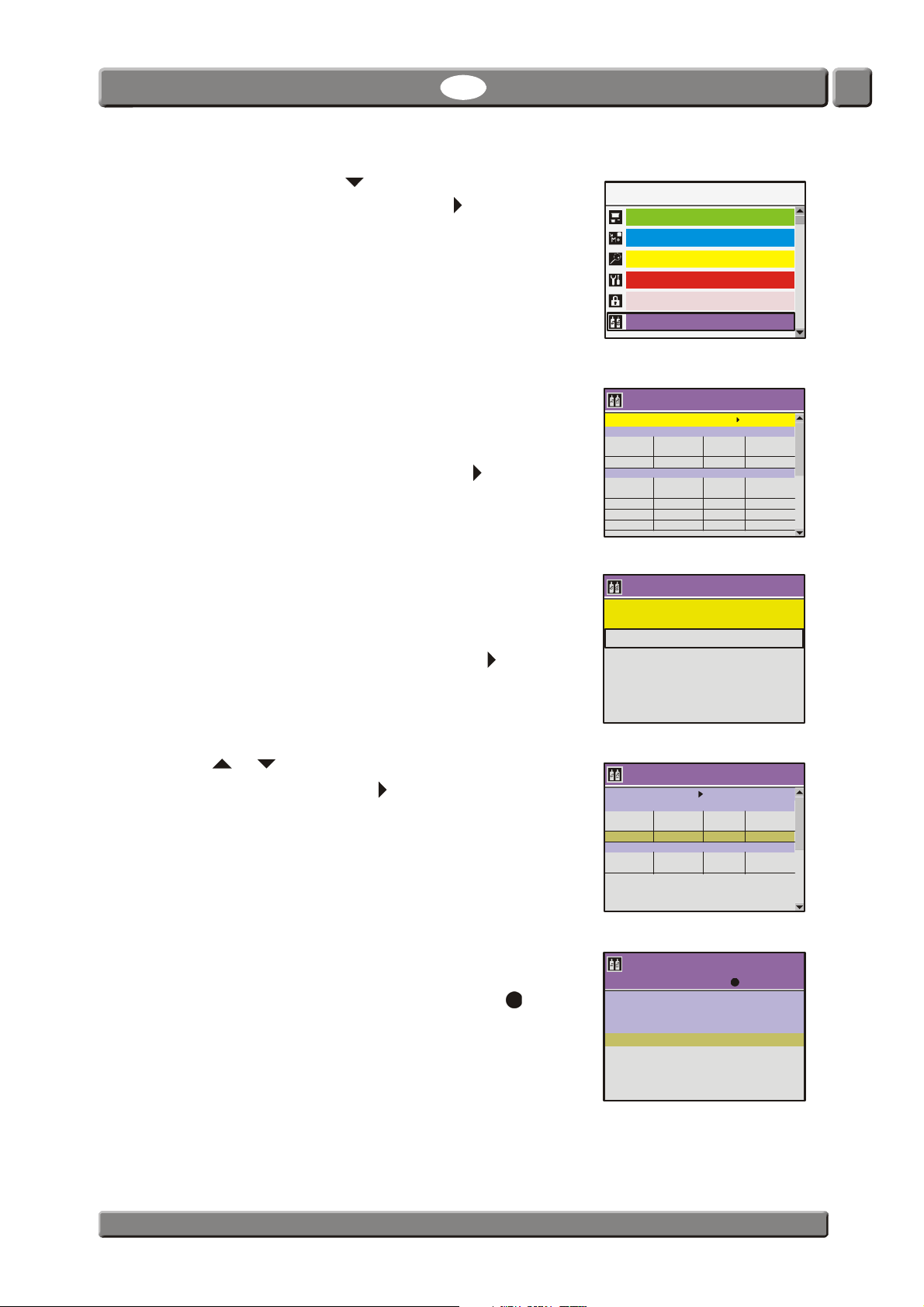
5. In the Main menu use key to scroll down to the
Calibration menu item then push the key to enter the
function.
6. The appearing Calibration menu holds a list of the
various sensors in the device.
For each sensor there is a table showing the appropriate
calibration parameters.
To proceed with the calibration push the key.
7. From this menu you can select between the following
items:
- Perform calibration
- Erase/enter calibration
Select Perform calibration, then push the key.
8. Use or key to select the 20,9460 field for the O
sensor (EC), then push the key.
Calibration
O sensor (EC)
O Response Pressure Calibration
CO Response Pressure Calibration
2
Calibration
Select sensor and press to begin calibration
9. The pump starts and now make sure to expose the
needle to a 20,946% O
Let measurement run for 10 min. then push key.
PBI-Dansensor A/S COPYRIGHT © PBI-300042-B 10/2010
gas.
2
Page 47
46 User Guide EN CheckMate 3
Warning
XXXXX
XXXXX
Old value:
New value:
Select and press
No
Yes
13:46
08/17/06
Information
Please wait
Calibrating
13:46
08/17/06
13:46
08/17/06
O sensor (EC)
O Response Pressure Calibration
% mV mbar date
CO sensor (100%)
CO Response Pressure Calibration
% mbar date
2
2
2
2
20,9460 XX,XXX XXXX,X XX/XX/XX
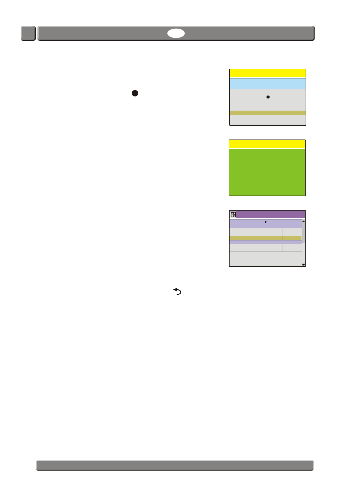
10. You will be asked to perform the calibration.
NOTE! Existing calibration value, if any, will be
overwritten.
Select "Yes" then push key.
11. The calibration will be executed.
Perform calibration?
12. When calibration has finished, the pump stops and the
display will return to the sensor menu.
Note that the fields for the 20,9460% gas now have
been updated with the values obtained during
calibration.
13. Now the O
sensor (EC) has been calibrated.
2
To return to the start screen push the key 4 times.
Calibration
Select sensor and press to begin calibration
PBI-300042-B 10/2010 COPYRIGHT © PBI-Dansensor A/S
Page 48
CheckMate 3 EN User Guide 47
product
Export
Export
port all products
Export users
Import users
Export CM3
Import CM3
all data collections
all products
Im
Export / Import
13:46
08/17/06
Standby
13:46
08/17/06
Export/Import
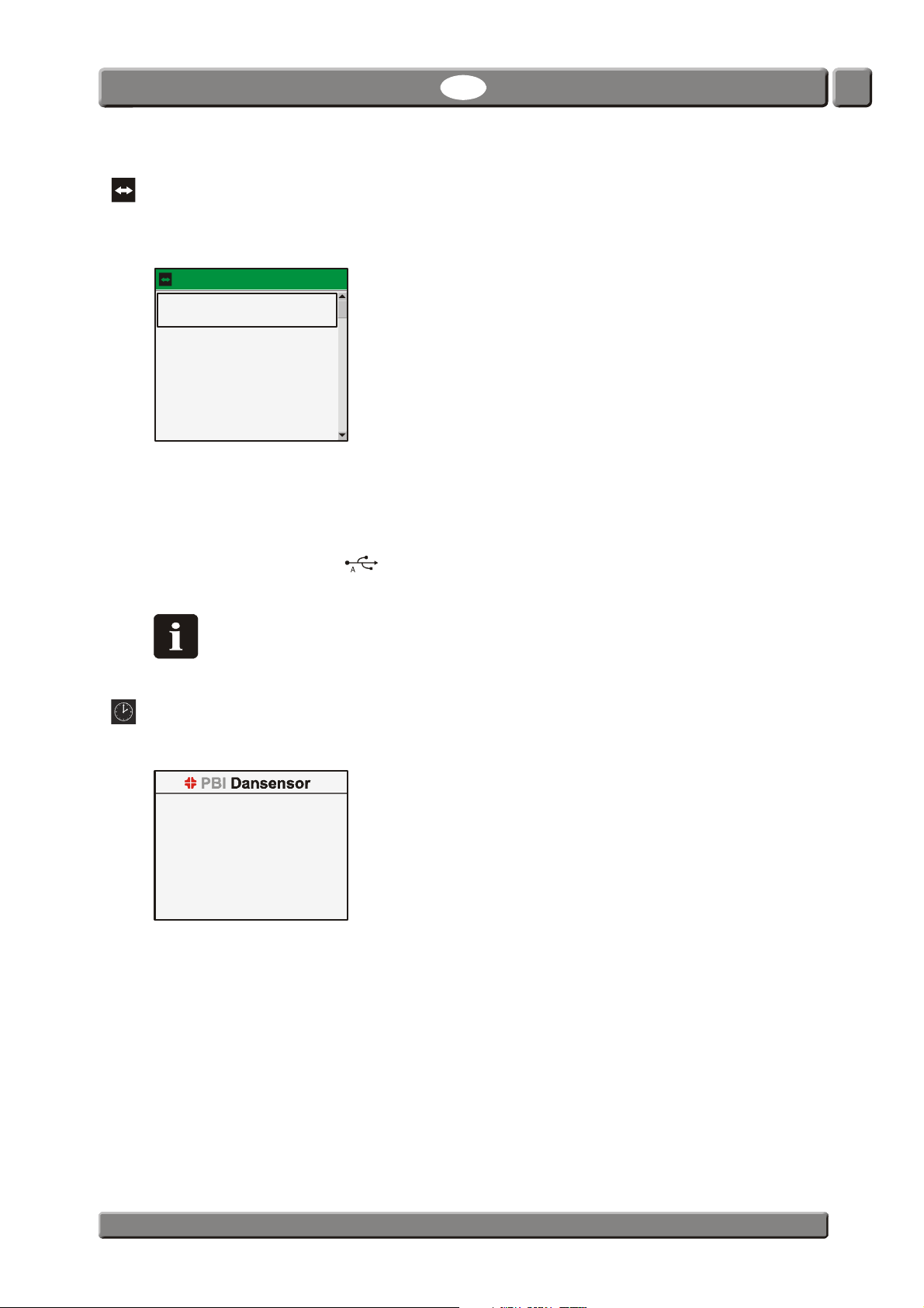
Selecting Export/Import from the Main menu will display a screen listing the various
functions for exporting and importing of data.
Export da ta collection of current
The functions cover export of product log data and export/import of product - and user data.
The Export/Import CM3 functions exports/imports products, users, and all non-device
specific settings.
The export and import functions requires for a USB memory key to be connected to the
USB A connector (labelled ) at the back of the device - see "Connection of additional
equipment" on page 13 for details.
NOTE! It is only possible to have one export file on a USB key. If a file is already on
the USB key it will be overwritten.
Standby
Selecting Standby from the Main menu will force the device into Standby mode.
See "Modes" on page 15 for details.
PBI-Dansensor A/S COPYRIGHT © PBI-300042-B 10/2010
Page 49
48 User Guide EN CheckMate 3
Sleep
13:46
08/17/06
English standard
Nederlands
Francais
Deutsch
Italiano
Svenska
Dansk
Español
Sleep
Selecting Sleep from the Main menu will force the device into Sleep mode.
See "Modes" on page 15 for details.
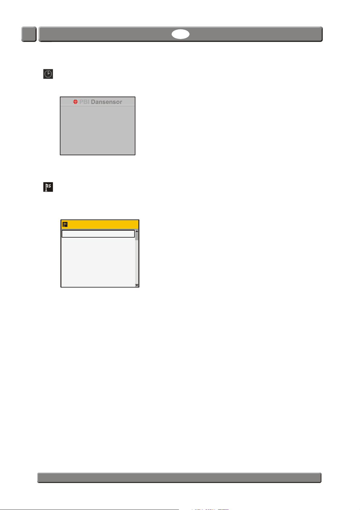
Language
Selecting Language from the Main menu will display a screen listing the available
languages.
Select language
When selecting a language all text throughout the menus will be displayed in this language.
PBI-300042-B 10/2010 COPYRIGHT © PBI-Dansensor A/S
Page 50
CheckMate 3 EN User Guide 49
D
H
W
4. Technical Information
Technical specifications
Electrical connections
Mains 100-240V AC, 50-60 Hz
Power consumption Zirconia O2 sensor: max 40W
Electrochemical O
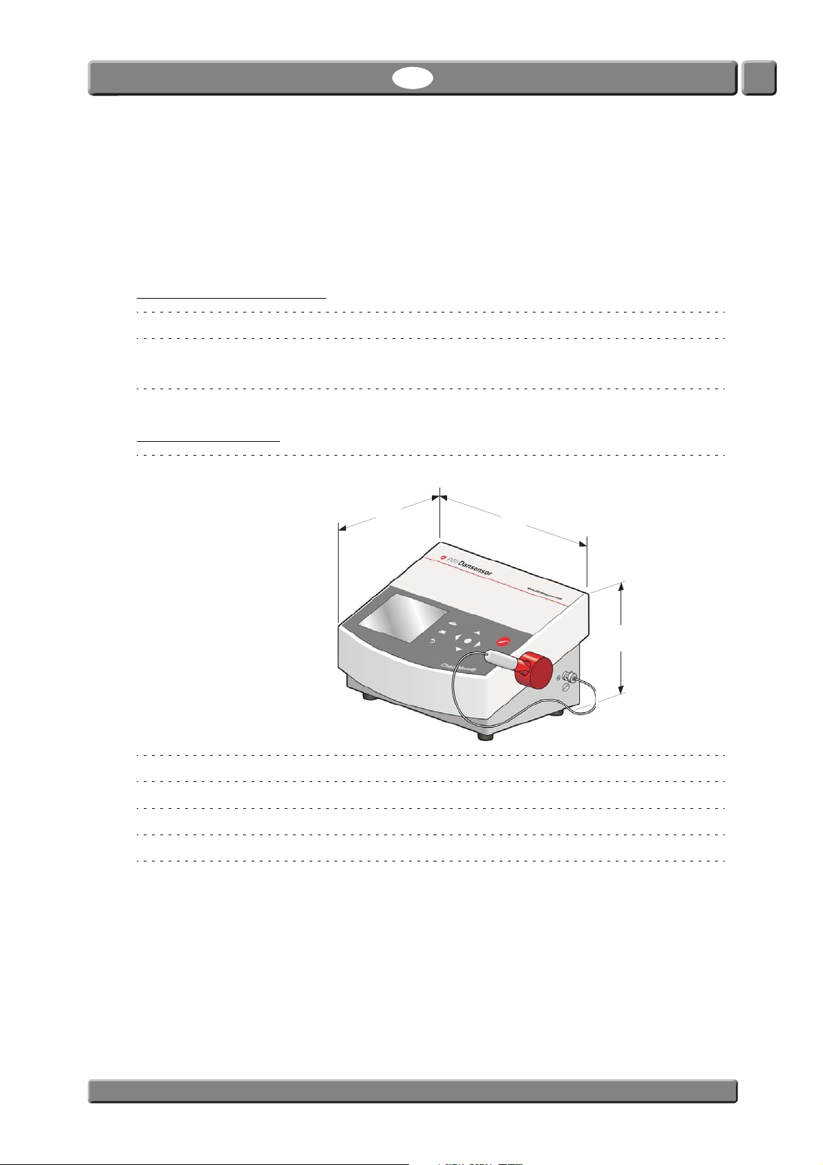
Mechanical data
Analyzer size 180 x 315 x 220 mm (H x W x D)
sensor: max 30W
2
Analyzer weight 3,7 kg
Box of one analyzer 400 x 320 x 300 mm (H x W x D)
Box weight 5,8 kg
IP classification IP 20
PBI-Dansensor A/S COPYRIGHT © PBI-300042-B 10/2010
Page 51

50 User Guide EN CheckMate 3
Connectivity
Network/LAN Ethernet 10/100 mbit/s Base-T with DHCP client or
fixed IP
RS232 D-SUB 9 DTE interface (male connedtor)
USB Host, USB 2.0 Connector type A, max current 100mA
Device, USB 2.0 Connector type B
Gas connection
Gas inlet Sample hose: Length 60 cm, Ø0,5mm
Sample type/connector: Needle 0,8x40mm
or
SmartPen 0,8x9mm
Filter/Water trap: 0,45 µ
Gas outlet Connection for hose (inner diameter Ø 3mm)
Basic specifications
Warm-up time Operational after 10 min.1
(60 minutes to full specifications)
Measuring ranges 0-100 % O2 and 0-100% CO
Ambient temperature Operational: +0 to +45 °C, less than 95 %RH,
non condensing
Storage: -20°C to +60°C, less than 95 %RH,
non condensing
Ambient pressure Operational: 900 hPa to 1050 hPa
Measurement gas Inert gasses (O2, CO2, N2 or Ar), less than 95 %RH,
non condensing.
Measurement gas flow 27 to 40 ml/min. (Typical flow 34 ml/min.)
Measurement gas temperature 5 °C to 35 °C
Sample pressure range Ambient +100 mbar -200mbar
1
Warm-up time is shortened at temporary power interrupts.
2
The flow will be lower than 27 ml/min when sample pressure is lower than atmospheric pressure.
2
2
PBI-300042-B 10/2010 COPYRIGHT © PBI-Dansensor A/S
Page 52

CheckMate 3 EN User Guide 51
Zirconia O2 sensor
Measure time Min. 3 sec. (incl. 1 sec. measure delay time)
1
Sample volume Min. 1,35 ml (with a 3 sec measuring time and a flow of
27 ml/min)
Typical sample volume 2,83 ml ( with a 5 sec measuring time and a flow of
34 ml/min)
Reference gas Ambient atmospheric air (20.9 % O2)
1
This time should be increased when the sample pressure is lower than atmospheric pressure.
Electrochemical O2 sensor
Measure time Min. 7 sec. (incl. 1 sec. measure delay time)
Sample volume Min. 3,15 ml (with a 7 sec. measuring time and a flow
of 27 ml/min)
Typical sample volume 3,97 ml (with a 7 sec. measuring time and a flow of
34 ml/min)
1
This time should be increased when the sample pressure is lower than atmospheric pressure.
1
CO2 sensor
Measure time Min. 10 sec. (including 1 sec measure delay time)
1
Sample volume Min. 4,5 ml (with a 10 sec measuring time and a flow of
27 ml/min)
Typical sample volume 8,5 ml (with a 15 sec measuring time and a flow of
34 ml/min)
1
This time should be increased when the sample pressure is lower than atmospheric pressure.
PBI-Dansensor A/S COPYRIGHT © PBI-300042-B 10/2010
Page 53

52 User Guide EN CheckMate 3
Accuracy specification (excl. calibration)
Zirkonia sensor resolution 0,1 % absolute in range above 10 %
0,01 % absolute in range above 1 %
0,001 % absolute in range below 1 %
Zirkonia sensor accuracy ±0,01 % absolute in range below 1 %
±1 % relative in range above 1 %
Electrochemical sensor resolution 0,1 % absolute
Electrochemical sensor accuracy O2 version: ±0,25 % absolute + 2% relative
< 25%
@ CO
2
O
version: ±0,9 % absolute + 2% relative
2
@ CO
25%
2
/CO2 version: ±0,25 % absolute + 2% relative
O
2
@ CO
< 25%
2
O
/CO2 version: ±0,5 % absolute + 2% relative
2
25%
@ CO
2
CO2 sensor resolution 0,1 % absolute
CO2 sensor accuracy ±0,5 % absolute ±1,5% of reading
Standard calibration specification
Calibration gasses (O2) 100ppm, 1000 ppm, 1%, 80% (balance N2)
20.9 % (Compressed dried atmosphere air)
Calibration gas accuracy < 3 %
System diffusion < 25 ppm
Measurement gas flow 34 ml/min ± 6 ml/min
Ambient temperature 23 °C ± 2 °C
Ambient pressure 1013 hPa ± 50 hPa
Total calibration accuracy (RMS) ± (25 ppm + 4 % of reading)
in the range 100ppm - 80%
PBI-300042-B 10/2010 COPYRIGHT © PBI-Dansensor A/S
Page 54
CheckMate 3 EN User Guide 53
Specification conditions
Ambient temperature +23 °C
Ambient pressure 1013 hPa
Measurement gas temperature +23 °C
Measurement gas flow 34 ml/min
NOTE! All gas concentrations are specified in volume percent.
Conformity
•CE
•RoHS
• China RoHS Phase 1 compliance
PBI-Dansensor A/S COPYRIGHT © PBI-300042-B 10/2010
Page 55

54 User Guide EN CheckMate 3
Consumable parts and options
Ordering items
When ordering any of the below listed items please state carefully the item number, the item
specification and the number of items wanted and send the order to your spare parts dealer.
Available User Guides
All user guides are available on:
• CD, User guides, CheckMate cpl. . . . . . . . . . . . . . . . . . . . . . . . . . . . . . . . . . . . . .PBI 300049
Consumable parts
• Kit, standard consumable, CheckMate 3 . . . . . . . . . . . . . . . . . . . . . . . . . . . . . .PBI 300436
- 5 pcs. Needle kit, Ø0.8mm (10 pcs.) ser. cpl. . . . . . . . . . . . . . . . . . . . . . . . .PBI 220078
- 2 pcs. Sampling kit cpl. . . . . . . . . . . . . . . . . . . . . . . . . . . . . . . . . . . . . . . . . . .PBI 251134
- 1 pc. Hose, Sample Gas (5 pcs. 600mm x Ø0.51mm) . . . . . . . . . . . . . . . .PBI 251394
- 2 pcs. Filter Kit 0.2µ (10 pcs.) cpl. . . . . . . . . . . . . . . . . . . . . . . . . . . . . . . . . .PBI 280206
- 3 pcs. Septum Ø15mm (1000 pcs.) ser. cpl. . . . . . . . . . . . . . . . . . . . . . . . . .PBI 940301
• Printer paper 57mm x 25 m (2 pcs.) ser. cpl. . . . . . . . . . . . . . . . . . . . . . . . . . . .PBI 220076
• Hose, Sample Gas (5 pcs. 600mm x Ø0.51mm). . . . . . . . . . . . . . . . . . . . . . . . .PBI 251394
• Filter Kit 0.2µ (10 pcs.) cpl.. . . . . . . . . . . . . . . . . . . . . . . . . . . . . . . . . . . . . . . . . .PBI 280206
• Printer Paper w/logo (2 pcs.) cpl. . . . . . . . . . . . . . . . . . . . . . . . . . . . . . . . . . . . . .PBI 270434
• Needle kit, Ø0.8mm (10 pcs.) ser. cpl.. . . . . . . . . . . . . . . . . . . . . . . . . . . . . . . . .PBI 220078
• Needle kit, Ø0.8mm (100 pcs.) ser. cpl . . . . . . . . . . . . . . . . . . . . . . . . . . . . . . . .PBI 280204
• Filter Kit 0.2µ (100 pcs.) cpl. . . . . . . . . . . . . . . . . . . . . . . . . . . . . . . . . . . . . . . . .PBI 280207
• Septum Ø15mm (100 pcs.) ser. cpl. . . . . . . . . . . . . . . . . . . . . . . . . . . . . . . . . . .PBI 940296
• Septum Ø15mm (1000 pcs.) ser. cpl. . . . . . . . . . . . . . . . . . . . . . . . . . . . . . . . . .PBI 940301
• Septum Ø15mm (10000 pcs.) ser. cpl. . . . . . . . . . . . . . . . . . . . . . . . . . . . . . . . .PBI 220157
Options
• Sampling Kit SmartPen . . . . . . . . . . . . . . . . . . . . . . . . . . . . . . . . . . . . . . . . . . . . .PBI 300433
• Barcode Scanner . . . . . . . . . . . . . . . . . . . . . . . . . . . . . . . . . . . . . . . . . . . . . . . . . .PBI 260339
• CheckMate PC Software . . . . . . . . . . . . . . . . . . . . . . . . . . . . . . . . . . . . . . . . . . . .PBI 290142
• Can Piercer. . . . . . . . . . . . . . . . . . . . . . . . . . . . . . . . . . . . . . . . . . . . . . . . . . . . . . .PBI 940247
Toxic and Hazardous Substances or Elements
(For China RoHS compliance)
See table on the next page.
PBI-300042-B 10/2010 COPYRIGHT © PBI-Dansensor A/S
Page 56
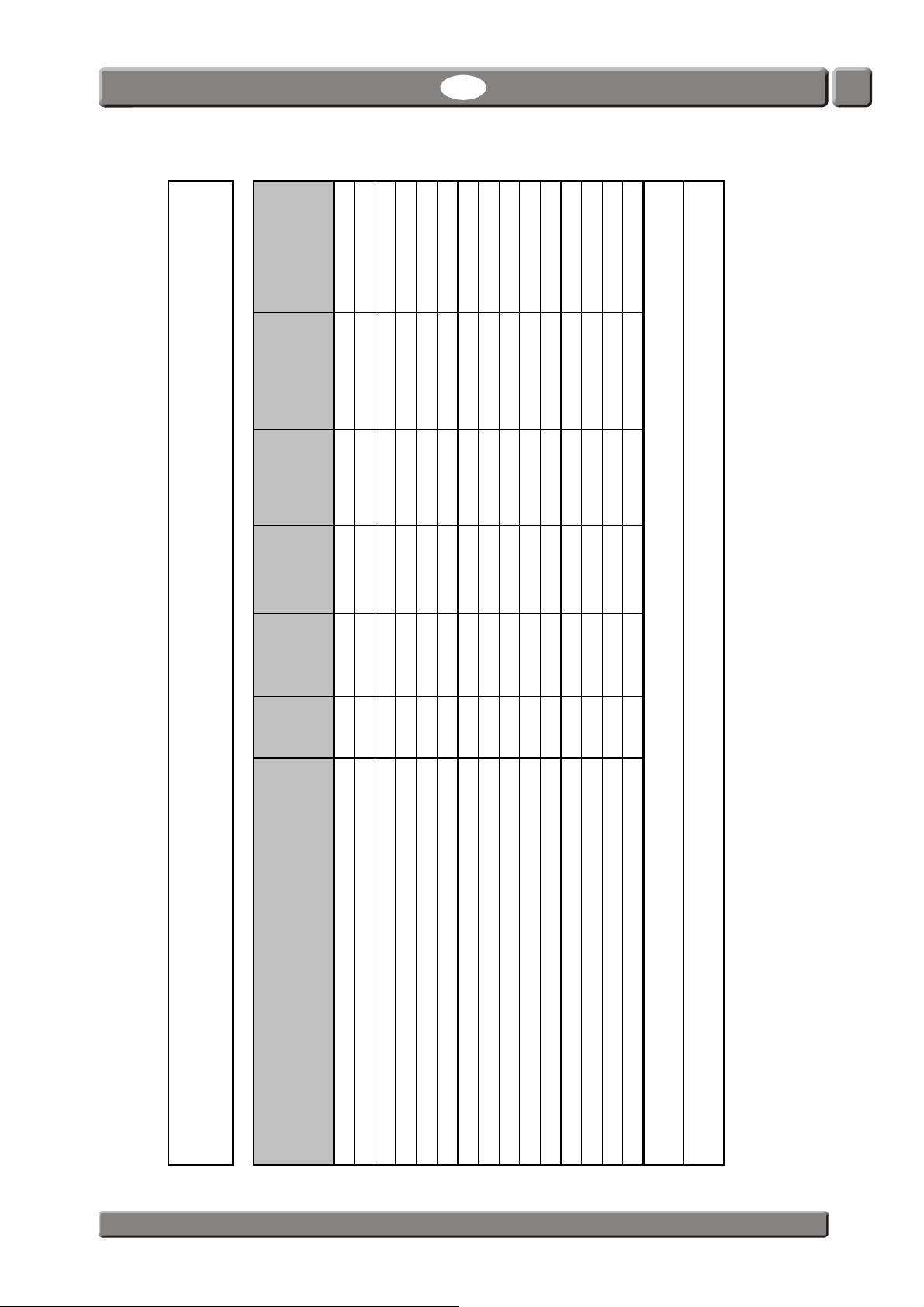
CheckMate 3 EN User Guide 55
Component Name㧔兓⒕⚜䱿᧥
Lead
杔
(Pb)
Mercury
ᳮ
(Hg)
Cadmium
柘
(Cd)
Hexavalent
Chromium
ચ杻䱊
(Cr6+)
Polybrominated
Biphenyls
ᄙ䅃▥勣啾
(PBB)
Polybrominated
Diphenyls Ethers
ᄙ䅃▥ℛ啾搩
(PBDE)
Metal enclosure㧔㊄ዻᄖᄂ㧕 OO O O O O
Sensor O2 Zirconia㧔ൻ枕㘱⯃᧥ OO O O O O
Sensor O2 EC㧔䟄▥ⷵ㺶㘱⯃᧥ XO O O O O
Sensor CO EC㧔䟄▥ⷵ㺶▥䭂㘱⯃᧥ OO O O O O
Sensor CO2 Infrared㧔儱⮥兎ℛ㺶▥䭂㘱⯃᧥ OO O O O O
Display panel (LCD)㧔LCD㣍䯉㨎᧥ OO O O O O
Printer unit㧔ᛂශ◤⏒᧥ OO O O O O
Power supply (PSU)㧔ଏ䟄᧥ OO O O O O
Printed circuit board assembly (Main PCB)㧔ශ㓸ᚑ 䟄恾㨎᧥ OO O O O O
Heater Unit㧔ട䍼◤⏒᧥ OO O O O O
Pump㧔᳆㾄
᧥ OO O O O O
Fan unit㧔歝㓖᧥ OO O O O O
Mounting hardware (screws, studs)㧔ⲷ€䷘揜ↅ᧥ OO O O O O
Internal cables㧔ౝ䟄冕᧥ OO O O O O
Sample hose kit㧔㉻㫆㺣丰᧥ OO O O O O
CheckMate 3
Toxic or Hazardous Substances or Elements
Ქኂ‛德㒥⏒侯
O: Indicates that the toxic substance contained in all the homogenous materials for this component is below the limit requirements in SJ/T11363-2006
ઍᚲએห 德㧟㠨⋩兓⒕䤓㦘㹡䓸德⚺摞⇝ℝ SJ/T11363-2006 㪖㓏尐㻑䤓⚺摞ᇭ
X: Indicates that the toxic substance contained in at least one of the homogenous materials for this component exceeds the limit requirments in SJ/T11363-2006
ઍએ⥋ዋ৻ 䱜⚛德㧟㠨⋩兓⒕䤓㦘㹡䓸德⚺摞怔扖 SJ/T11363-2006 㪖㓏
尐㻑䤓⚺摞ᇭ
PBI-Dansensor A/S COPYRIGHT © PBI-300042-B 10/2010
Page 57

56 User Guide EN CheckMate 3
PBI-300042-B 10/2010 COPYRIGHT © PBI-Dansensor A/S
 Loading...