

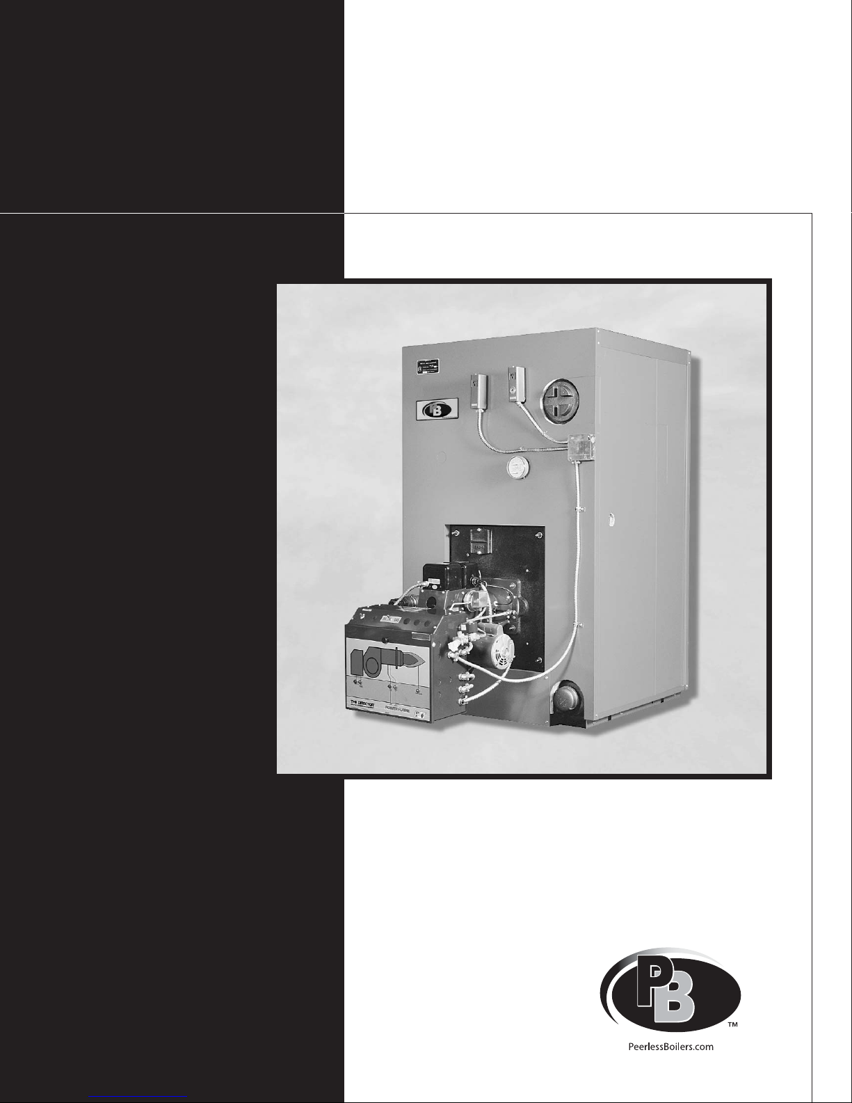
PB Heat TC Series, TC-04, TC-05, TC-06, TC-07 Installation, Operation & Maintenance Manual
...Page 1
TC
™
Gas/Oil Boilers
Series
Oil, Gas &
Installation,
Operation &
Maintenance
Manual
Page 2

USING THIS MANUAL 1
A. MANUAL ORGANIZATION . . . . . . . . . . . . . .1
B. SPECIAL ATTENTION BOXES . . . . . . . . . . . .1
1. PREINSTALLATION 2
A. GENERAL . . . . . . . . . . . . . . . . . . . . . . . . . . . .2
B. CODES & REGULATIONS . . . . . . . . . . . . . . .2
C. BOILER LOCATION . . . . . . . . . . . . . . . . . . . . .2
D. COMBUSTION & VENTILATION AIR . . . . . . .3
E. CHIMNEY & BREECHING. . . . . . . . . . . . . . . .3
F. BOILER FOUNDATION . . . . . . . . . . . . . . . . . .4
G. INSTALLATION SURVEY . . . . . . . . . . . . . . . .5
H. PLANNING THE LAYOUT . . . . . . . . . . . . . . . .6
I. VERIFY COMPONENTS . . . . . . . . . . . . . . . . . .6
2. BOILER ASSEMBLY 9
A. PACKAGED BOILERS . . . . . . . . . . . . . . . . . . .9
B. ASSEMBLED BLOCKS . . . . . . . . . . . . . . . . . .9
C KNOCKDOWN BOILERS . . . . . . . . . . . . . . . .9
D. HYDROSTATIC TESTING . . . . . . . . . . . . . . .13
E. CLEAN-OUT COVER INSTALLATION . . . . .13
F. BURNER MOUNTING PLATE . . . . . . . . . . .14
G. REAR OBSERVATION PORT . . . . . . . . . . . .14
H. FLUE COLLECTOR INSTALLATION . . . . . . .15
I. BURNER MOUNTING . . . . . . . . . . . . . . . . . .15
3. INSTALLATION 16
A. PREPARATION . . . . . . . . . . . . . . . . . . . . . . .16
B. STEAM BOILER PIPING . . . . . . . . . . . . . . . .16
C. MULTIPLE STEAM BOILER PIPING . . . . . . .17
D. WATER BOILER PIPING . . . . . . . . . . . . . . . .17
E. MULTIPLE WATER BOILER PIPING . . . . . . .21
F. TANKLESS HEATER INSTALLATION . . . . . .21
G. JACKET PREPARATION . . . . . . . . . . . . . . . .22
H. JACKET ASSEMBLY . . . . . . . . . . . . . . . . . .22
I. FUEL PIPING . . . . . . . . . . . . . . . . . . . . . . . . .23
J. INSTALL CONTROLS AND TRIM . . . . . . . .24
4. OPERATION 28
A. STARTING THE BOILER . . . . . . . . . . . . . . . .28
B. CLEANING BOILER WATERWAYS . . . . . . .29
5. MAINTENANCE 30
6. REPAIR PARTS 32
7. BOILER RATING & DIMENSIONS 34
TABLE OF CONTENTS
TABLE OF CONTENTS
Page 3

1
A. MANUAL ORGANIZATION
The Series TC™ Installation, Operation & Maintenance
Manual is divided into five basic sections:
1. Preinstallation (Sections A through I)
2. Boiler Assembly (Sections A through I)
3. Installation (Sections A through J)
4. Operation (Section A through B)
5. Maintenance
B. SPECIAL ATTENTION BOXES
Throughout this manual you will see special attention
boxes intended to supplement the instructions and make
special notice of potential hazards. These categories
mean, in the judgment of the PB Heat, LLC:
Indicates special attention is needed, but not directly
related to potential personal injury or property
damage.
NOTICE
Indicates a condition or hazard which will or can
cause moderate personal injury or property damage.
CAUTION
DANGER
Indicates a condition or hazard which will cause
severe personal injury, death or major property
damage.
USING THIS MANUAL
USING THIS MANUAL
Indicates a condition or hazard which may potentially
cause severe personal injury, death or major property
damage.
WARNING
Page 4
2
A. GENERAL
Series TC™ boilers are supplied completely knocked
down for field assembly, completely assembled as
packaged boilers or as assembled blocks of cast iron
sections. All items should be inspected for damage upon
receipt and any damage reported to wholesaler and
trucking company. All components should be stored in a
clean, dry area.
Carefully read these instructions, burner instructions, and
control instructions before beginning work. This boiler
must be installed by a qualified contractor. The boiler
warranty may be voided if the boiler is not installed
correctly.
B. CODES & REGULATIONS
1. All work is to be peformed in strict accordance with
the requirements of state and local regulating
agencies and codes dealing with boiler installations.
2. In the absence of such local requirements, the
following codes should be followed:
ASME B & PV Code, Section IV – "Heating Boilers"
ASME B & PV Code, Section VI – "Care and
Operation of Heating Boilers"
ANSI/NFPA 31 – "Installation of Oil Burning
Equipment"
ANSI Z223.1 – "National Fuel Gas Code"
ANSI/NFPA 70 – "National Electric Code"
ASME CSD-1 – "Controls & Safety Devices for
Automatically Fired Boilers"
ANSI/NFPA 211 – "Chimneys, Fireplaces, Vents and
Solid Fuel Burning Appliances"
3. In Canada, the following codes should be used in
addition to those in Section 1.B.2.
CAN1.3.1-77 (R1996) – "Industrial and Commercial
Gas Fired Package Boilers”
CSA B140.0-M87 – "General Requirements for Oil
Burning Equipment"
CSA B140.7.2-1967 – "Oil-Fired Steam and Hot
Water Boilers for Commercial and Industrial Use"
CAN/CSA C22.2 No.0-M91 – "General
Requirements – Canadian Electrical Code Part II
CSA C22/2 No.3-M1988 – "Electrical Features of
Fuel Burning Equipment"
C. BOILER LOCATION
1. Locate the boiler close to the chimney to minimize
the breeching length, but allow adequate clearance
for piping, service, maintenance, and tankless coil
replacement. A clearance of 36" [914 mm] on all
sides of the boiler and 48" [1219 mm] in front of the
boiler is recommended for serviceability.
PREINSTALLATION
1. PREINSTALLATION
WARNING
Do not install this boiler on carpeting. A significant
fire hazard could result, with potential for property
damage, personal injury or death.
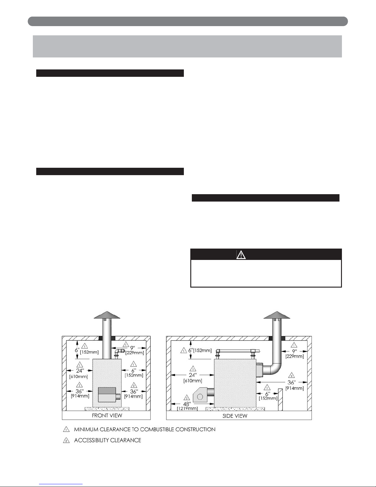
Figure 1.1: Clearance Requirments
Page 5
3
2. The minimum clearances to combustible materials,
based on ANSI/NFPA 31 are as follows. See
Figure 1.1.
Right Side: 6 inches [152 mm]
Left Side: 24 inches [610 mm]
Rear of Jacket: 6 inches [152 mm]
Front of Boiler: 24 inches [610 mm]
Top of Jacket: 6 inches [152 mm]
Vent/Chimney/Flue Collector: 9" [229 mm]
D. COMBUSTION & VENTILATION AIR
1. Provide adequate air for combustion and ventilation.
2. Unless the boiler room construction and natural air
infiltration supply all necessary combustion air,
provide an outside air opening or duct. The free
cross-sectional area of the opening or duct shall meet
or exceed 1 square inch [645 square millimeters] per
4000 Btu/hr [1.17 kW] input for all installed
appliances. At altitudes greater than 2000 feet [610
meters] above sea level, this requirement is to be
increased by 4% per each thousand feet [304
meters] above sea level.
Example: at 5000 feet above sea level.
Free Area = 1 + (0.04 x 5)
Free Area =
1.20 sq. in.
Free Area =
4000
Btu/hr
Example: at 1500 meters above sea level.
Free Area = 1 + (0.04 x
1500
)
Free Area = 1 + (0.04 x
304
Free Area = 1.2 x 645 =
772 sq. mm
Free Area = 1 + (0.04 x
1.17 kW
3. The boiler room must never be under negative
pressure. If exhaust fans or other equipment that can
potentially cause a negative pressure are used, the
air openings must be engineered to assure a neutral
or slightly positive pressure in the boiler room at all
times of operation.
a) If the equipment design and air openings cannot
assure this, the boiler must be located in a room
isolated from these appliances.
b) If the vent system terminates in any area where
wind-generated down drafts are likely, install a
suitable vent cap which can control wind effects.
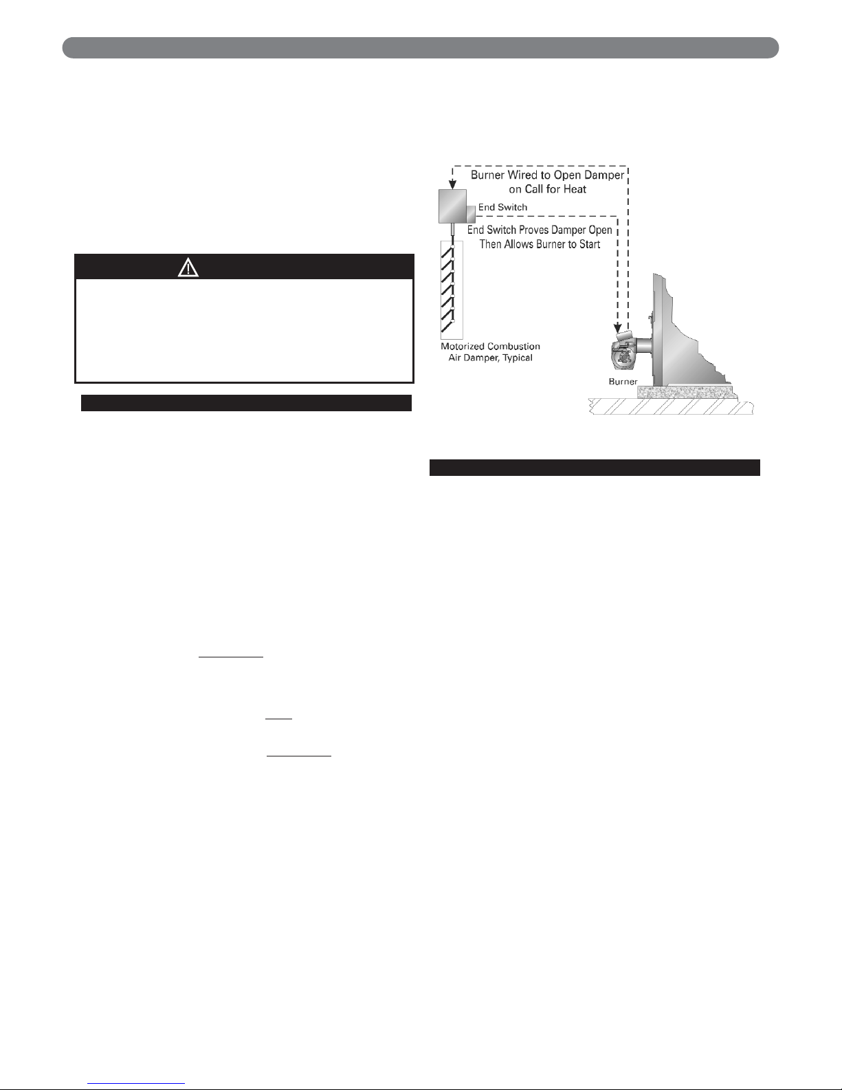
4. If motorized dampers are used on the combustion
and ventilation air openings they must include an
interlock device that prevents the boiler from
operating if they do not open. See Figure 1.2 for this
configuration.
E. CHIMNEY & BREECHING
1. Vent System Inspection:
a) Inspect the existing chimney or vent system.
Look for damage due to corrosion or other
causes. Make sure the vent system is in good
condition and all vent connectors and chimneys
are properly supported.
b) Inspect the chimney liner and repair or replace as
necessary.
2. Vent System Sizing:
a) The vent system must be sized and installed to
remove all combustion products. If the vent
system is not sized properly, the burner may not
operate correctly. This may cause poor
combustion or sooting.
b) The breeching connection between the boiler
and chimney should be as short as possible with
a minimum number of elbows.
c) Breeching Diameter:
The breeching must be the same diameter as the
boiler outlet for Model TC-04 through TC-16 and
18" [457 mm] diameter for Model TC-17 & TC18 Boilers.
The vent sizes for all Series TC™ Boilers are
listed in the "Ratings and Dimensions" section of
this manual.
d) If extreme length, excessive elbows, or a
reduction in diameter is necessary, consult your
PB Heat representative for recommendations.
PREINSTALLATION
Figure 1.2: Motorized Vent Damper Interlock
WARNING
If this boiler is to be installed on combustible
flooring, consult local building authorities for proper
installation, or in the absence of regulations consult
ANSI/NFPA 31 – "Installation of Oil Burning
Equipment." Failure to comply with this warning may
result in a fire, severe personal injury or death.
Page 6
4
3. Vent System Installation:
a) The vent system and installation must be in
accordance with the current edition of the
American National Standard ANSI/NFPA 211,
"Chimneys, Fireplaces, Vents, and Solid Fuel
Burning Appliances" or applicable provisions of
local building codes.
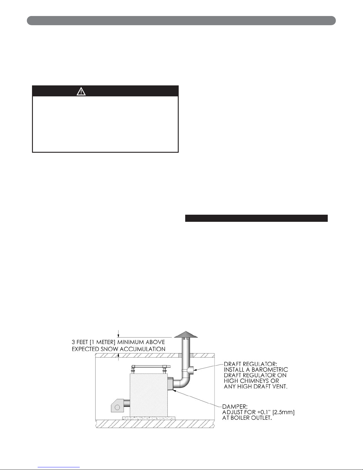
b) Vent Terminations:
1. Vent terminations must be extended to three
feet above expected snow accumulation. See
Figure 1.3.
2. If the vent system terminates in any area
where wind-generated down drafts are likely,
install a suitable vent cap to help control
wind effects.
c) Vent Connection Support
1. Support the vent system independently of the
boiler flue connection.
2. Provide support of the vent connector
(breeching) at maximum 12 foot [3.66 meter]
intervals to prevent sagging.
d) Horizontal runs of vent are to be sloped back
toward the boiler at approximately ¼" per foot [2
cm per meter].
e) Breeching used with forced draft boilers must be
sealed, of heavy gauge construction and must
comply with all applicable codes of construction.
f) Exterior Vents: Insulate vent pipes that pass
through unheated spaces sufficiently to prevent
excessive condensation and ensure adequate
draft.
g) Multiple Appliances: Do not vent multiple
appliances with venting that operates under
positive pressure into a common chimney or vent
connector. This may cause products of
combustion to circulate into the boiler room
when one of the appliances is not operating.
h) Draft Regulator: Install a barometric draft
regulator when using a high chimney or any high
draft vent.
1. This is necessary to prevent negative draft
conditions in the boiler.
2. Excessive draft will cause flame lifting, poor
combustion, or impingement.
4. Vent System Operation:
a) This boiler is designed to fire only with a
pressurized combustion chamber. The breeching
and vent may be sized for negative, neutral, or
positive pressure as desired.
b) Maintain maximum of +0.1 inches [2.5 mm] of
water at the boiler outlet.
c) Avoid excessive negative pressure in the
combustion chamber. This may cause the flame
to lift off of the burner causing unstable
combustion. In addition, this may cause
impingement of the burner flame onto the crown
sheet, which may lead to overheating.
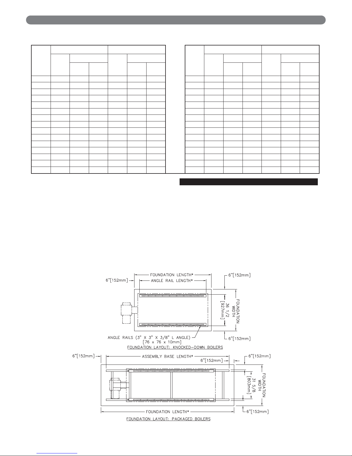
F. BOILER FOUNDATION
1. If the boiler room floor is not level or if additional
structural support is required, provide a level
concrete foundation pad for the boiler. The flooring
and structural support system must be suitable for
the operating weight of the boiler and any connected
piping.
a) Figure 1.4 shows the Foundation Layout for
Knocked-Down Boilers and Packaged Boilers.
b) Dimensions for the foundation are given in Table
1.1a and 1.1b.
2. Do not operate the boiler until the foundation, if
newly poured concrete, has thoroughly cured. Rapid
heating may damage the concrete due to expanding
moisture.
Figure 1.3: Typical Vent Termination
PREINSTALLATION
WARNING
Configuration of the breeching and chimneys on
some installations may result in a positive breeching
pressure. In these cases, the breeching must be
constructed of pressure tight materials. Consult
local building authorities for proper installation.
Failure to comply with this warning may result in
carbon monoxide poisoning or fire, resulting in
severe personal injury or death.
Page 7
5
3. If the boiler is installed in a penthouse or if wiring of
any sort is run underneath the boiler foundation,
construct the foundation with a provision for air flow
between the main floor and the top of the boiler
foundation.
a) An acceptable foundation would be concrete
blocks laid on their sides with the openings lined
up.
b) If the foundation must be a concrete slab, use an
air cell high temperature insulating board, at least
½" [13 mm] thick, with aluminum backing. ½"
[13 mm] thick, high temperature millboard with
aluminum backing is also acceptable. Place the
insulating board on the slab, with the aluminum
side up, between the angle rails.
G. INSTALLATION SURVEY
For new and existing installations, a Steam or Water
Installation Survey is available from PB Heat, LLC. The
survey will provide information on how a steam or water
boiler works with your specific system and will provide
an overview of steam or water system operation.
You can also use this survey to locate system problems
that will have to be corrected. To obtain copies of the
Steam or Water Installation Survey, contact your PB
Heat, LLC Representative or download it from
PeerlessBoilers.com.
PREINSTALLATION
Figure 1.4: Foundation Layout
Boiler
Model
Knocked-Down Boilers Packaged Boilers
Boiler
Model
Knocked-Down Boilers Packaged Boilers
Rail
Length
(inches)
Foundation
Base
Length
(inches)
Foundation
Rail
Length
(mm)
Foundation
Base
Length
(mm)
Foundation
Width
(inches)
Length
(inches)
Width
(inches)
Length
(inches)
Width
(mm)
Length
(mm)
Width
(mm)
Length
(mm)
TC- 04 34.19 48.5 46.25 66.19 48.5 78.25 TC- 04 868 1232 1175 1681 1232 1988
TC- 05 42.25 48.5 54.25 74.25 48.5 86.25 TC- 05 1073 1232 1378 1886 1232 2191
TC- 06 50.31 48.5 62.50 82.31 48.5 94.50 TC- 06 1278 1232 1588 2091 1232 2400
TC- 07 58.38 48.5 70.50 90.38 48.5 102.50 TC- 07 1483 1232 1791 2296 1232 2604
TC- 08 66.44 48.5 78.50 98.44 48.5 110.50 TC- 08 1688 1232 1994 2500 1232 2807
TC- 09 74.50 48.5 86.50 106.50 48.5 118.50 TC- 09 1892 1232 2197 2705 1232 3010
TC- 10 82.56 48.5 95.00 114.56 48.5 127.00 TC- 10 2097 1232 2413 2910 1232 3226
TC- 11 90.63 48.5 103.00 122.63 48.5 135.00 TC-11 2302 1232 2616 3115 1232 3429
TC- 12 98.69 48.5 111.00 130.69 48.5 143.00 TC-12 2507 1232 2819 3320 1232 3632
TC- 13 106.75 48.5 119.00 138.75 48.5 151.00 TC-13 2711 1232 3023 3524 1232 3835
TC- 14 114.81 48.5 127.00 146.81 48.5 159.00 TC-14 2916 1232 3226 3729 1232 4039
TC- 15 122.88 48.5 135.00 154.88 48.5 167.00 TC-15 3121 1232 3429 3934 1232 4242
TC- 16 130.94 48.5 143.00 162.94 48.5 175.00 TC-16 3326 1232 3632 4139 1232 4445
TC- 17 139.00 48.5 151.00 171.00 48.5 183.00 TC-17 3531 1232 3835 4343 1232 4648
TC- 18 147.06 48.5 159.00 179.06 48.5 191.00 TC-18 3735 1232 4039 4548 1232 4851
Table 1.1a: Foundation Dimensions
(U.S. Customary Units)
Table 1.1b: Foundation Dimensions
(SI Metric Units)
Page 8
6
H. PLANNING THE LAYOUT
Prepare sketches and notes of the layout to minimize the
possibility of interference with new or existing
equipment, piping, venting, and wiring.
I. VERIFY COMPONENTS
1. Packaged Boilers: All standard components are
located in the boiler package with the following
exceptions:
a) Relief Valves are assembled with piping and
included in a separate carton to prevent damage
in shipment.
b) The Return Yoke is not mounted or assembled
for shipment. This assembly is included in a
separate carton.
c) In some cases, the Burner and/or Gas Train may
be shipped separately.
d) The Optional Barometric Draft Damper is
shipped in a separate carton.
2. Knocked-down Boilers: All components are shipped
for field assembly. See Tables 1.2a and 1.2b for
standard components. See Tables 1.3 through 1.8
for optional components.
3. Assembled Block Boilers: These are similar to
knocked-down boilers except the angle rails, sections
and section assembly kit cartons are pre-assembled
into a single shipping level component.
PREINSTALLATION
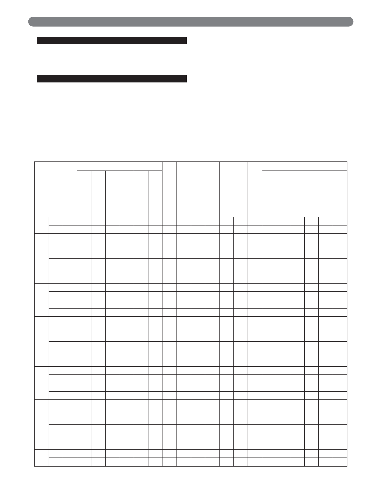
Table 1.2a: Series TC™ Shipping List (Steam Boilers)
Boiler Model Number
Angle Rail
Standard Sections Flue Outlet
Controls Carton
Trim Carton
Section Assembly
Cartons
Graphite Port
Connector Carton
Miscellaneous Parts
Carton
Jacket Panels
Front
Rear
Plain Intermediate
Supply Intermediate
Flue Collector
Outlet Adapter
Jacket Channel
Carton
Jacket Front/Back
Carton
Jacket Top/Side
Carton
TC- 04
Qty. 2 1 1 1 1 1 1 1 1 1 1 1 1 1
SCN 74004 76000 76001 76002 76003 76060 88512 77000 76050 76053 76070 75004 76030 76031
TC- 05
Qty. 2 1 1 2 1 1 1 1 1 1 1 1 1 1
SCN 74005 76000 76001 76002 76003 76060 88512 77000 76051 76054 76070 75005 76030 76032
TC- 06
Qty. 2 1 1 2 2 1 1 1 1 1 1 1 1 1 1
SCN 74006 76000 76001 76002 76003 76060 88512 77001 76052 76055 76070 75006 76030 76033 76035
TC- 07
Qty. 2 1 1 3 2 1 1 1 2 2 1 1 1 1 1
SCN 74007 76000 76001 76002 76003 76061 88512 77001 76050 76053 76070 75007 76030 76031 76036
TC- 08
Qty. 2 1 1 4 2 1 1 1 1 1 1 1 1 1 1 1 1
SCN 74008 76000 76001 76002 76003 76061 88512 77002 76050 76051 76053 76054 76070 75008 76030 76031 76037
TC- 09
Qty. 2 1 1 5 2 1 1 1 2 2 1 1 1 1 1
SCN 74009 76000 76001 76002 76003 76062 88512 77002 76051 76054 76071 75009 76030 76031 76038
TC- 10
Qty. 2 1 1 6 2 1 1 1 1 1 1 1 1 1 1 1 1
SCN 74010 76000 76001 76002 76003 76062 88512 77002 76051 76052 76054 76055 76071 75010 76030 76032 76038
TC- 11
Qty. 2 1 1 6 3 1 1 1 2 2 1 1 1 1 2
SCN 74011 76000 76001 76002 76003 76062 88512 77003 76052 76055 76071 75011 76030 76032 76036
TC- 12
Qty. 2 1 1 7 3 1 1 1 1 2 1 2 1 1 1 1 1 1
SCN 74012 76000 76001 76002 76003 76062 88512 77003 76050 76051 76053 76054 76071 75012 76030 76032 76036 76037
TC- 13
Qty. 2 1 1 8 3 1 1 1 3 3 1 1 1 1 2
SCN 74013 76000 76001 76002 76003 76062 88512 77003 76051 76054 76071 75013 76030 76032 76037
TC- 14
Qty. 2 1 1 9 3 1 1 1 1 2 1 2 1 1 1 1 1 1
SCN 74014 76000 76001 76002 76003 76063 88512 77004 76050 76052 76053 76055 76071 75014 76030 76032 76037 76038
TC- 15
Qty. 2 1 1 10 3 1 1 1 1 2 1 2 1 1 1 1 2
SCN 74015 76000 76001 76002 76003 76063 88512 77004 76051 76052 76054 76055 76071 75015 76030 76032 76038
TC- 16
Qty. 2 1 1 11 3 1 1 1 3 3 1 1 1 1 1 1 1
SCN 74016 76000 76001 76002 76003 76063 88512 77004 76052 76055 76071 75016 76030 76032 76035 76039 76038
TC- 17
Qty. 2 1 1 12 3 1 1 1 1 4 4 1 1 1 1 2 2
SCN 74017 76000 76001 76002 76003 76063 76064 88512 77005 76051 76054 76071 75017 76030 76034 76040 76037
TC- 18
Qty. 2 1 1 13 3 1 1 1 1 3 1 3 1 1 1 1 1 2 1 1
SCN 74018 76000 76001 76002 76003 76063 76064 88512 77005 76051 76052 76054 76055 76071 75018 76030 76034 76040 76037 76038
Page 9

7
PREINSTALLATION
Boiler Model Number
Angle Rail
Standard Sections Flue Outlet
Controls Carton
Trim Carton
Yoke
Section Assembly Cartons
Graphite Port Connector
Carton
Miscellaneous Parts Carton
Jacket Panels
Front
Rear
Plain Intermediate
Flue Collector
Outlet Adapter
Jacket Channel Carton
Jacket Front/Back
Carton
Jacket Top/Side Carton
TC- 04
Qty. 2 1 1 2 1 1 1 1 1 1 1 1 1 1
SCN 74004 76000 76001 76002 76060 78510 77030 76072 76050 76053 76070 75004 76030 76031
TC- 05
Qty. 2 1 1 3 1 1 1 1 1 1 1 1 1 1
SCN 74005 76000 76001 76002 76060 78510 77031 76072 76051 76054 76070 75005 76030 76032
TC- 06
Qty. 2 1 1 4 1 1 1 1 1 1 1 1 1 1 1
SCN 74006 76000 76001 76002 76060 78510 77031 76072 76052 76055 76070 75006 76030 76033 76035
TC- 07
Qty. 2 1 1 5 1 1 1 1 2 2 1 1 1 1 1
SCN 74007 76000 76001 76002 76061 78510 77032 76072 76050 76053 76070 75007 76030 76031 76036
TC- 08
Qty. 2 1 1 6 1 1 1 1 1 1 1 1 1 1 1 1 1
SCN 74008 76000 76001 76002 76061 78510 77032 76072 76050 76051 76053 76054 76070 75008 76030 76031 76037
TC- 09
Qty. 2 1 1 7 1 1 1 1 2 2 1 1 1 1 1
SCN 74009 76000 76001 76002 76062 78510 77032 76072 76051 76054 76071 75009 76030 76031 76038
TC- 10
Qty. 2 1 1 8 1 1 1 1 1 1 1 1 1 1 1 1 1
SCN 74010 76000 76001 76002 76062 78510 77032 76072 76051 76052 76054 76055 76071 75010 76030 76032 76038
TC- 11
Qty. 2 1 1 9 1 1 1 1 2 2 1 1 1 1 2
SCN 74011 76000 76001 76002 76062 78510 77033 76072 76052 76055 76071 75011 76030 76032 76036
TC- 12
Qty. 2 1 1 10 1 1 1 1 1 2 1 2 1 1 1 1 1 1
SCN 74012 76000 76001 76002 76062 78510 77033 76072 76050 76051 76053 76054 76071 75012 76030 76032 76036 76037
TC- 13
Qty. 2 1 1 11 1 1 1 1 3 3 1 1 1 1 2
SCN 74013 76000 76001 76002 76062 78510 77033 76072 76051 76054 76071 75013 76030 76032 76037
TC- 14
Qty. 2 1 1 12 1 1 1 1 1 2 1 2 1 1 1 1 1 1
SCN 74014 76000 76001 76002 76063 78510 77033 76072 76050 76052 76053 76055 76071 75014 76030 76032 76037 76038
TC- 15
Qty. 2 1 1 13 1 1 1 1 1 2 1 2 1 1 1 1 2
SCN 74015 76000 76001 76002 76063 78510 77034 76072 76051 76052 76054 76055 76071 75015 76030 76032 76038
TC- 16
Qty. 2 1 1 14 1 1 1 1 3 3 1 1 1 1 1 1 1
SCN 74016 76000 76001 76002 76063 78510 77034 76072 76052 76055 76071 75016 76030 76032 76035 76039 76038
TC- 17
Qty. 2 1 1 15 1 1 1 1 1 4 4 1 1 1 1 2 2
SCN 74017 76000 76001 76002 76063 76064 78510 77034 76072 76051 76054 76071 75017 76030 76034 76040 76037
TC- 18
Qty. 2 1 1 16 1 1 1 1 1 3 1 3 1 1 1 1 1 2 1 1
SCN 74018 76000 76001 76002 76063 76064 78510 77034 76072 76051 76052 76054 76055 76071 75018 76030 76034 76040 76037 76038
Table 1.2b: Series TC™ Shipping List (Water Boilers)
Page 10
8
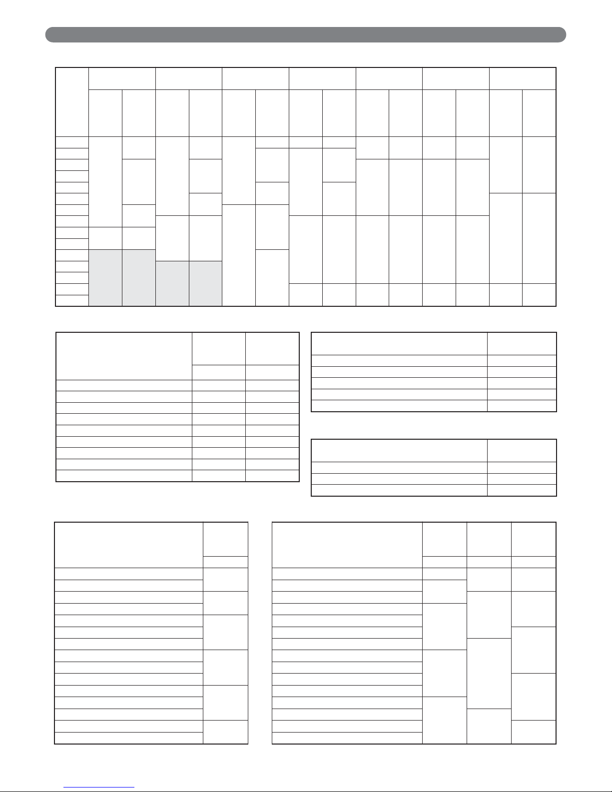
PREINSTALLATION
Boiler
Model
Beckett Carlin Gordon-Piatt
Power Flame
(Gas) Power Flame (Oil)
Power Flame
(Gas/Oil) Webster
Mounting
Plate Stock
Code
Burner
Model
Mounting
Plate Stock
Code
Burner
Model
Mounting
Plate Stock
Code
Burner
Model
Mounting
Plate Stock
Code
Burner
Model
Mounting
Plate Stock
Code
Burner
Model
Mounting
Plate Stock
Code
Burner
Model
Mounting
Plate Stock
Code
Burner
Model
TC- 04
76027
CF1400
76027
702CRD
76023
R8 76028 J30A
76028 C1 76028 C1
76028 JB1
TC- 05
R8.2
76027
J50ATC- 06
CF2300
801CRD
76027 C2 76027 C2
TC- 07
TC- 08
R8.4
C2TC- 09
1050FF
D
76025 JB2
TC- 10
CF2500
76026
R10.1
TC- 11
76024
1150FF
D
76024 C3 76024 C3 76024 C3
TC- 12
76024 CF3500
TC- 13
TC- 14
R10.2
TC- 15
TC- 16
TC- 17
76022 C4 76022 C4 76022 C4 76022 JB3
TC- 18
Table 1.3: Burner Mounting Plates
Section
Standard
With
Inspection
Tappings
Stock Code Stock Code
Front 76000 76010
Intermediate 76002 ---Intermediate with Boss 76005 76007
Intermediate with LWCO Tappings 76011 ---Intermediate Supply with Boss 76003 76008
Intermediate Supply w/ LWCO Taps 76012 ---Intermediate Heater 76004 76009
Intermediate Heater w/ LWCO Taps 76013 ---Back 76001 76006
Description Stock Code
Heater Cover Plate Assembly 76075
Heater Cover Plate Gasket 74019
Tankless Coil -8 GPM 76073
Tankless Coil -12 GPM 76074
Return Yoke - Water Boiler 76072
Description Stock Code
Steam Controls Carton - L404A 88511
Steam Controls Carton - PA404A 88512
Water Controls Carton - L4006A 78510
Table 1.4: Standard & Optional Sections
Table 1.5: Tankless Coil & Cover Plate Options
Table 1.6: Controls Cartons
Description
15 PSI
[103 kPa]
Steam
Description
30 PSI
[207 kPa]
50 PSI
[345 kPa]
80 PSI
[552 kPa]
Stock Code Stock Code Stock Code Stock Code
Steam Trim Carton TC-04
77000
Water Trim Carton TC-04 77030
77050 77080
Steam Trim Carton TC-05 Water Trim Carton TC-05
77031
Steam Trim Carton TC-06
77001
Water Trim Carton TC-06
77051
77081Steam Trim Carton TC-07 Water Trim Carton TC-07
77032
Steam Trim Carton TC-08
77002
Water Trim Carton TC-08
Steam Trim Carton TC-09 Water Trim Carton TC-09
77082
Steam Trim Carton TC-10 Water Trim Carton TC-10
77052
Steam Trim Carton TC-11
77003
Water Trim Carton TC-11
77033
Steam Trim Carton TC-12 Water Trim Carton TC-12
Steam Trim Carton TC-13 Water Trim Carton TC-13
77083
Steam Trim Carton TC-14
77004
Water Trim Carton TC-14
Steam Trim Carton TC-15 Water Trim Carton TC-15
77034
Steam Trim Carton TC-16 Water Trim Carton TC-16
77053Steam Trim Carton TC-17
77005
Water Trim Carton TC-17
77084
Steam Trim Carton TC-18 Water Trim Carton TC-18
Table 1.7: Steam Trim Cartons Table 1.8: Water Trim Cartons
Page 11
9
A. PACKAGED BOILERS
1. All assemblies should be carefully inspected for
shipping damage on arrival. Any damage should be
reported immediately to the shipping company and
PB Heat.
2. Remove shrink-wrap and inspect the jacket, cast iron
sections, and burner (if supplied) for damage.
Remove the left side panels and inspect the clean out
covers for damaged or missing silicone seals.
3. Continue to Section 3, Installation.
B. ASSEMBLED BLOCKS
1. All assemblies should be carefully inspected for
shipping damage on arrival. Any damage should be
reported immediately to the shipping company and
PB Heat.
2. Check the component list in Tables 1.2a and 1.2b
and packing slip to assure that all shipping level
items are received. Inspect all packages for shipping
damage.
3. Continue to Section 2.F, Burner Mounting Plate
Installation.
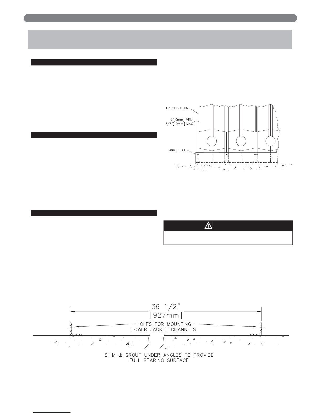
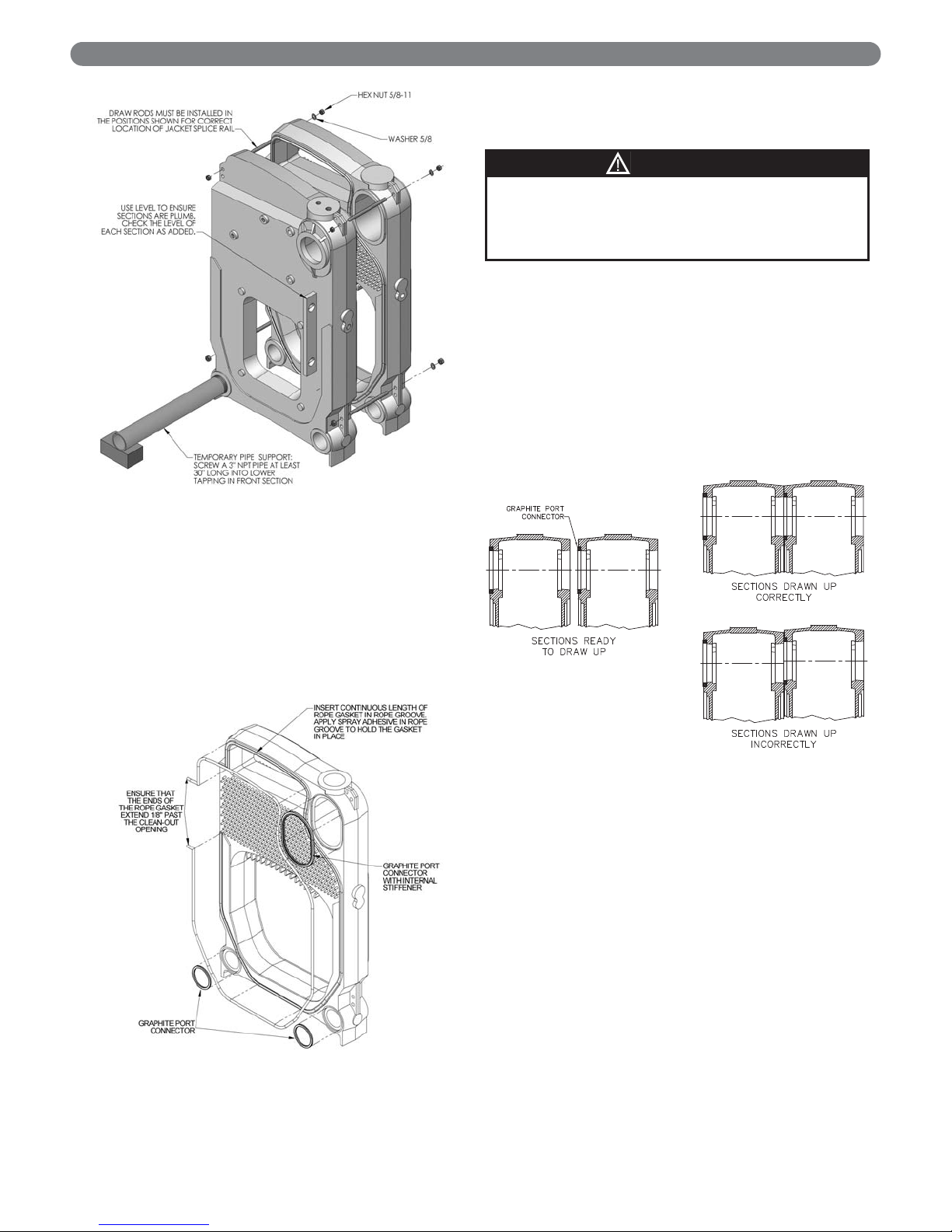
C KNOCKDOWN BOILERS
1. Check the component list in Tables 1.2a and 1.2b
and packing slip to assure that all shipping level
items are received. Inspect all packages for shipping
damage.
2. Report any damage to the shipping company and
PB Heat immediately.
3. Lay the angle rails provided at the point of final
installation. Set the angles in parallel position
measuring 36-1/2" [927 mm] outside-to-outside of
angles as shown in Figure 2.1. Shim the angles to
level them and grout under angles after the sections
are assembled.
4. Place the Front Section in position on the angles as
shown in Figure 2.2. The end of the floor angle must
either be flush with the boss for the wash out
connection or extend beyond it by as much as
3/8" [10 mm].
5. The Front Section should be supported vertically as
shown in Figure 2.3. Install a 3" NPT x 30" [762
mm] long pipe in the wash out connection at the
rear of the section and block with wood.
6. Inspect the port connector recesses and rope groove
on the cast iron rear section for dirt and obstructions.
7. Clean the port connector recesses with a stiff wire
brush.
ASSEMBLY
2. ASSEMBLY
Figure 2.1: Angle Rail Placement
Figure 2.2: Front Section Placement
The cast iron sections are top heavy. Handle with care
to avoid tipping or falling.
WARNING
Page 12
10
8. Apply the spray-on adhesive supplied with the boiler
to the rope groove. This will hold the rope gasket in
place during assembly.
9. Apply a length of rope gasket (supplied in the
section assembly cartons), avoiding bends and
twists in the rope. Ensure that the ends of the rope
gasket extend past the clean-out cover opening as
shown in Figure 2.4.
10. Install the large graphite port connector with steel
inner ring into the upper port making sure that the
inner ring stays inside the port connector.
11. Install the two small, circular, graphite port
connectors with steel inner rings in the lower recess
ports. Make sure that the inner rings stay inside the
port connectors. Spray adhesive used for attaching
rope may be used to keep the port connectors in
place during assembly.
12. Select the correct intermediate section (refer to Table
2.2), and slide it into place against the front section.
Ensure that the sections are plumb and the port
connectors are properly seated in the port recesses as
indicated in Figure 2.5.
13. Install the draw rods as shown in Figure 2.3 and
tighten them lightly. Note: Draw rods must be
installed as shown to ensure correct installation of
the Jacket Channel Splice Rail.
14. Inspect the rope gasket to ensure that it remains in
the rope groove.
15. Check the section alignment and port connector
position by looking through the ports. If necessary,
reposition the port connector by loosening the draw
rods and then retightening them.
16. Check the floor angles and sections for alignment.
ASSEMBLY
Figure 2.3: Front Section Support
Figure 2.4: Rope Gasket and Port Connector
Instalation
Handle the graphite port connectors with care. Do
not bend, twist, stretch or drop the port connectors. If
the graphite port conector is damaged it must be
replaced.
NOTICE
Figure 2.5: Drawing Up Sections
Page 13

11
17. Gently tighten the draw rods to the torque
specification and sequence as described in Table 2.1.
Make sure the port connectors stay inside the boiler
ports. Do not completely tighten any draw rod out of
sequence. Gradually work each side until the correct
torque is reached.
18. If any ports develop leaks during the hydrostatic test,
the torque may be increased up to 200 ft. lbs. [270
Nm] on the upper right and 150 ft. lbs. [203 Nm] on
both of the lower ports.
19. Prepare the rope groove and gasket recess on the
intermediate section as described for the front
section in paragraph 2.C.6 through 2.C.11.
20. Select the next appropriate section in accordance
with Table 2.2.
21. For TC-08 through TC-18 refer to Figure 2.6, 2.7
and Table 2.3 for correct placement of nuts and
washers for jacket channel splice piece.
ASSEMBLY
Table 2.1: Torque Specifications for Series TC™
Boiler with Graphite Port Connectors
Seq.
No.
Draw Rod
Position
Torque
(ft. lbs.)
Torque
(Nm)
1 Upper Right 25 34
2 Lower Left 25 34
3 Lower Right 25 34
4 Upper Left 10 14
5 Upper Right 50 68
6 Lower Left 50 68
7 Lower Right 50 68
8 Upper Right 75 102
9 Lower Left 75 102
10 Lower Right 75 102
11 Upper Left 30 41
12 Upper Right 125 169
13 Lower Left 125 169
14 Lower Right 125 169
15 Upper Right 125 169
16 Upper Left 40 54
Table 2.2a: Steam Section Arrangement
F Front Section
T Intermediate Section w/5" Steam Tapping (Steam Only)
TLIntermediate Section w/5" Steam & LWCO Tappings (Steam Only)
H Optional Intermediate Section w/Heater Connections
HLOptional Intermediate Section w/Heater Connections & LWCO Tapping
P Plain Intermediate Section
PLPlain Intermediate Section & LWCO Tappings
B Back Section
F T HLB
F H TLH B
F T HLT H B
F T HLP T H B
F T HLP H T H B
F T HLP H P T H B
F H TLH P H P T H B
F H TLH P T H P T H B
F H TLH P T H P H T H B
F H TLH P H T H P H T H B
F H TLH P H T H P H P T H B
F H TLH P H P T H P H P T H B
F H TLH P H P H T H P P H T H B
F H TLH P H P H T H P
H
P H T H B
F H TLH P H P H
P
T H P
H
P H T H B
TC-04
TC-05
TC-06
TC-07
TC-08
TC-09
TC-10
TC-11
TC-12
TC-13
TC-14
TC-15
TC-16
TC-17
TC-18
Notes:
1) Tapped Intermediate Sections with LWCO Tappings (T
L
) are optional and if not used are replaced with a Tapped Intermediate Section (T).
2) Intermediate Sections with Heater Connections (H) & (H
L
) are optional. The locations shown indicate the possible placement of these sections if they
are ordered. Unless Intermediate Heater Sections are specified, the sections provided will be Plain Intermediate Sections (P) or (P
L
).
3) Sections with Low Water Cut-Off (LWCO) Tappings are optional. However, if used, they must be placed at the third position from the front in order to
assure proper jacket fit.
Page 14

12
ASSEMBLY
F P HLP H P P H B
F H PLH P H P P H B
F H PLH P P H P P H B
F H PLH P P H P H P H B
F H PLH P H P H P H P H B
F H PLH P H P H P H P P H B
F H PLH P H P P H P H P P H B
F H PLH P H P H P H P P H P H B
F H PLH P H P H P H P
H
P H P H B
F H PLH P H P H
P
P H P
H
P H P H B
TC-04
TC-05
TC-06
TC-07
TC-08
TC-09
TC-10
TC-11
TC-12
TC-13
TC-14
TC-15
TC-16
TC-17
TC-18
Notes:
1) Intermediate Sections with Heater Connections (H) & (H
L
) are optional. The locations shown indicate the possible placement of these sections if they
are ordered. Unless Intermediate Heater Sections are specified, the sections provided will be Plain Intermediate Sections (P) or (P
L
).
2) Sections with Low Water Cut-Off (LWCO) Tappings are optional. However, if used, they must be placed at the third position from the front in order to
assure proper jacket fit.
F P HLB
F H PLH B
F P HLP H B
F P HLP P H B
F P HLP H P H B
Table 2.2b: Water Section Arrangement
Figure 2.6: Numbered Section Illustration
Page 15

13
D. HYDROSTATIC TESTING
1. Plug all openings in the boiler waterways and fill the
boiler with cold water. While filling the boiler, recheck the torque on all ports and tighten the draw
rods if necessary.
2. Hydrostatically test the boiler for leaks in accordance
with ASME Code, Section IV.
a) Steam Boilers: The assembled boiler shall be
subjected to a hydrostatic test pressure of not less
than 45 psig [310 kPa].
b) Water Boilers: The assembled boiler shall be
subjected to a hydrostatic test pressure of not less
than 1-1/2 times the maximum allowable
working pressure.
c) The test pressure shall not exceed the minimum
requirements shown above by more than 10 psi
[69 kPa].
3. If any port connector leaks, tighten the draw rods
until either the joint achieves full metal-to-metal
contact or until or the maximum torque is reached
(Upper Right - 200 ft. lbs. [270 Nm]; Lower Ports 150 ft. lbs.[203 Nm]). Check the torque on the other
draw rods that may have been affected by the draw
rod that was tightened.
E. CLEAN-OUT COVER INSTALLATION
1. Attach the clean-out cover plates and insulation to
the clean-out openings on the left side of the boiler.
Use the T-bolt assemblies and hex nuts provided in
the Section Assembly Cartons. See Figure 2.8.
2. Press each clean-out cover plate with insulation over
the protruding T-bolts until the bolts punch through
the insulation. Install a 5/16" flat washer and 5/16"
brass nut on each bolt and tighten until the
insulation forms a good seal around the clean-out
opening.
3. Seal tops and bottoms of insulation with silicone
sealant.
ASSEMBLY
Table 2.3: Splice Piece Nut & Washer Locations
Boiler Model Splice Piece & Washer Locations
TC- 04 N/A
TC- 05 N/A
TC- 06 N/A
TC- 07 N/A
TC- 08 Between Sections 3-4 & Sections 5-6
TC- 09 3-4 & 5-6
TC- 10 5-6 & 7-8
TC- 11 5-6 & 7-8
TC- 12 5-6 & 7-8
TC- 13 5-6 & 7-8
TC- 14 7-8 & 9-10
TC- 15 5-6 & 7-8 9-10 & 11-12
TC- 16 5-6 & 7-8 9-10 & 11-12
TC- 17 5-6 & 7-8 9-10 & 11-12
TC- 18 5-6 & 7-8 11-12 & 13-14
Figure 2.7
Note: Splice Piece nuts and washers are to be installed as shown in Figure 2.7 on
the draw rods that connect the sections indicated. The sections are numbered
from front to back as indicated in Figure 2.6. The Splice Pieces are shown in
Section 3 in Figure 3.12.
Do not exceed the maximum torque specifications
(upper Right – 200 ft. lbs. [270 Nm]; Lower Ports –
150 ft. lbs. [203 Nm]). Tighten the rods in the
sequence shown in Table 2.2.
Do not continue to tighten the sections after metalto-metal contact is made. Over-tightening the draw
rods will not improve the seal and may cause
damage to the castings.
NOTICE
When the boiler is put into operation for the first
time, the temperature should be brought up slowly
(low fire on burners with this capability).
NOTICE
Page 16

14
. BURNER MOUNTING PLATE
F. BURNER MOUNTING PLATE
INSTALLATION
1. Inspect the rope groove on the Burner Mounting
Plate for dirt and obstructions. Use a wire brush if
necessary to clean the groove.
2. Spray the rope groove with the spray adhesive
provided in the Misc. Parts Carton and apply the
3/8" diameter rope gasket.
3. Install the 7/16" x 2-1/2" Studs provided into the four
threaded holes around the perimeter of the burner
opening in the Boiler Front Section as shown in
Figure 2.9.
4. Insert the Burner Insulation Block into the burner
opening with the notch for the Observation Port on
the top left side.
5. Place the Burner Mounting Plate over the block and
force the block inward until the Studs extend far
enough through the holes to accept 7/16" Hex Nuts
and Washers. Tighten the nuts.
6. Use a long drill, awl, or other such tool to create holes
in the Insulation Block for four 1/4" machine screws.
7. Install the 1/4" x 5" machine screws through the
holes in the Burner Mounting Plate, supporting the
Insulation Block on the inside to prevent tearing.
8. Install the stainless steel washers and 1/4" hex nuts
on the inside of the Insulation Block and tighten
lightly. Be careful not to crush the insulation.
9. Install the four 3/8-16 x 1-1/4" studs provided into
the screw seats provided on the Burner Mounting
Plate.
10. When the burner is installed, the hole in the
Insulation Block for the Burner may need to be
enlarged and shaped. This can be cut with a
hacksaw blade.
G. REAR OBSERVATION PORT
INSTALLATION.
1. Assemble Rear Observation Port as shown in Figure
2.10:
a) Lift up the flapper door on the inside of the
Observation Port and insert the Hex Head Cap
Screw provided in the Misc. Parts Carton.
b) Slide the Spring over the hex head screw and
thread the Hex Nut onto the screw.
c) Thread the Knob onto the Hex Head Screw
behind the nut and lock into position using the
jam nut.
ASSEMBLY
Figure 2.8: Clean-Out Cover Installation
Figure 2.9: Burner Mounting Plate Installation
Figure 2.10: Rear Observation Port Assembly
Page 17

15
2. Thread the 5/16" x 1-1/2" studs into the screw seats
around the rear observation port opening in the
Boiler Back Section.
3. Apply a thin layer of furnace cement over the
mounting flap.
4. Install the Rear Observation Port Assembly on the
Boiler Back Section using three 5/16" hex nuts and
washers.
H. FLUE COLLECTOR INSTALLATION
1. Screw the eight 5/16-18 x 1-1/2" studs provided into
the screw seats around the flue collector outlet on the
Boiler Back Section.
2. Place the 1/8" [3 mm] thick x 3/4" [19 mm] wide
Bolt Tape provided in the Misc. Parts Carton over
the studs.
3. Place the flue collector in position and install the
5/16" washers and nuts. Tighten the nuts uniformly.
4. Open the Slide Damper to the full open position to
prepare for adjustment during Burner
commissioning.
5. Install 1/2" brass plug from Misc. Parts Carton.
I. BURNER MOUNTING
1. Read the Burner Instruction Manual before starting.
2. Remove the Burner from its crate. Verify that all
components are included with the burner.
3. Place the high temperature gasket specified by the
Burner Manufacturer on the Burner Mounting Plate
and secure the Burner using 3/8" flat washers and
hex nuts provided.
4. If the Burner is supplied with a pedestal support,
install it per the Burner Manufacturer’s Instructions.
The pedestal supports the burner and prevents
undue stress on the Boiler Castings.
ASSEMBLY
Figure 2.11: Rear Flue Collector Installation
Page 18

16
A. PREPARATION
1. The boiler must be hydrostatically pressure tested as
indicated in Section 2, paragraph D.
2. The jacket panels are designed so that they may be
installed after the boiler is piped. Use nipples long
enough to extend through the jacket.
B. STEAM BOILER PIPING
1. Refer to the PB Heat Steam Installation Survey for
guidance with steam boiler piping and components.
2. Piping for steam boilers is shown in Figure 3.1, 3.2,
and 3.3. Table 3.1 contains a pipe size schedule for
steam boilers.
3. Series TC™ Boilers are intended to be piped with
one, two or three risers to the header depending on
the boiler size.
a) Table 3.1 shows a pipe schedule for steam boiler
headers.
b) See Figure 3.1 for a typical piping arrangement
for boilers with one riser. (TC-04 & TC-05)
c) See Figure 3.2 for a typical piping arrangement
for boilers with two risers. (TC-06 through TC-10)
d) See Figure 3.3 for a typical piping arrangement
for boilers with three risers.
(TC-11 through TC-18)
4. A Hartford loop, as shown in Figures 3.1, 3.2 and
3.3 is recommended in all steam boiler installations.
The loop prevents the boiler from being drained
completely due to a leak in a return line.
5. Pumped Return Systems:
a) For pumped return systems, install a spring-
loaded check valve on the pump discharge. This
will prevent boiler water from backing up into the
condensate receiver.
b) If the pump discharge is looped above the
normal water level, install a spring-loaded check
valve at the connection to the boiler return. This
will ensure water under pressure in the vertical
pipe preventing water hammer due to hot
condensate flashing to steam.
INSTALLATION
3. INSTALLATION
Table 3.1: Piping Schedule
Do not reduce the size or number of risers shown in
Table 3.1. If the risers are undersized or incorrectly
placed, a sloped water line may occur in the boiler.
This may lead to the overheating of boiler sections.
CAUTION
Figure 3.1: Typical piping arrangement for boilers
with one riser.
Figure 3.2: Typical piping arrangement for boilers
with two risers.
Steam Boiler Piping
Boiler Model
Number of
5" NPT
Risers
Header Size
(NPT)
Equalizer Size
(NPT
TC-04 & TC-05 1 5" 2-1/2"
TC-06 & TC-07 2 5" 2-1/2"
TC-08 to TC-10 2 6" 4"
TC-11 to TC-18 3 8" 4"
Page 19

17
c) Install a flow regulating valve on the pump
discharge to allow throttling of the pump flow.
Excess return flow may cause water hammer and
water level fluctuations.
d) Use a Hartford Loop connection. Oversize the
equalizer slightly to make sure water doesn’t
spray into the header and cause hammering.
6. Always locate the steam supply take-off between the
equalizer and the last boiler riser. Failure to do this
will cause water carryover into the system because
the condensate will collect at the entrance to the
steam main.
7. Pitch the steam header to allow condensate to flow
toward the equalizer.
8. Feedwater requirements for steam boilers at full input
are shown in Tables 3.2a and 3.2b. Addition of
water to the boiler should be controlled by sensing
the boiler water level.
9. 1" NPT water column tappings are provided on the
front section for mounting low water cutoffs and level
controllers.
10. The front section has 3" NPT tappings at the base for
installation of 3" NPT close nipples and 3" NPT pipe
caps. Removal of caps allows flushing of sediment
from the boiler.
C. MULTIPLE STEAM BOILER PIPING
1. Figure 3.4 shows typical piping for multiple steam
boiler gravity return systems.
2. Figure 3.5 shows typical piping for multiple steam
boiler pumped return systems.
3. Provide separate feed lines for multiple steam boiler
pumped return systems. Use either separate feed
pumps or electrically actuated valves to isolate the
boiler feed. This is necessary to provide reliable level
control and avoid nuisance performance problems.
4. Condensate return units are not recommended for
multiple boiler installations. Use a boiler feed system
which is actuated by a boiler control that responds to
the needs of the boiler.
5. Install a float & thermostatic (F&T) trap at the boiler
normal water level on each of the boilers in a multiple
boiler system with pumped returns. This will prevent
flooding of idle boilers due to condensation of steam.
D. WATER BOILER PIPING
1. Refer to the Peerless®Water Installation Survey for
guidance with water boiler piping and components.
2. Typical piping for a Series TC™ water boiler is shown
in Figure 3.6.
INSTALLATION
Table 3.2a: Feedwater Requirements -
US Customary Units
Figure 3.3: Typical piping arrangement for boilers
with three risers.
Boiler
Model
I=B=R
Gross
Output
MBH
Evap. Rate
1
GPM
Minimum
Feedwater
Pump Flow
2
GPM
Condensate
Receiver
Capacity
3
Gallon
TC- 04 900 1.86 3.7 37
TC- 05 1166 2.41 4.8 48
TC- 06 1433 2.96 5.9 59
TC- 07 1699 3.50 7.0 70
TC- 08 1965 4.05 8.1 81
TC- 09 2232 4.60 9.2 92
TC- 10 2498 5.15 10.3 103
TC- 11 2764 5.70 11.4 114
TC- 12 3031 6.25 12.5 125
TC- 13 3297 6.80 13.6 136
TC- 14 3563 7.35 14.7 147
TC- 15 3830 7.90 15.8 158
TC- 16 4096 8.45 16.9 169
TC- 17 4362 9.00 18.0 180
TC- 18 4629 9.55 19.1 191
Boiler
Model
I=B=R
Gross
Output
KW
Evap. Rate
1
ltr/min
Minimum
Feedwater
Pump Flow
2
tr/min
Condensate
Receiver
Capacity
3
Liter
TC- 04 264 7.0 14.1 141
TC- 05 342 9.1 18.2 182
TC- 06 420 11.2 22.4 224
TC- 07 498 13.2 26.5 265
TC- 08 576 15.3 30.7 307
TC- 09 654 17.4 34.8 348
TC- 10 732 19.5 39.0 390
TC- 11 810 21.6 43.2 432
TC- 12 888 23.7 47.3 473
TC- 13 966 25.7 51.5 515
TC- 14 1044 27.8 55.6 556
TC- 15 1122 29.9 59.8 598
TC- 16 1200 32.0 64.0 640
TC- 17 1278 34.1 68.1 681
TC- 18 1357 36.2 72.3 723
Table 3.2b: Feedwater Requirements -
SI Metric Units
1. Evaporation rate is based on heat of vaporization at 212°F, 970 BTU/lbm.
2. Minimum feedwater pump flow is based on 2 times evaporation rate.
3. Condensate receiver capacities are based on 20 minute steam
1. Evaporation rate is based on heat of vaporization at 100°C, 2257 kJ/kb.
2. Minimum feedwater pump flow is based on 2 times evaporation rate.
3. Condensate receiver capacities are based on 20 minute steam cycle. Chart
3. shows actual capacity, not gross receiver volume
Page 20

18
3. A return yoke as shown in Figure 3.7 is provided as
standard equipment for each water boiler. Assemble
each joint as follows:
a) Cover edges and outer surface of the gasket with
a thin layer of petroleum-free silicone lubricant
(supplied).
b) Install each gasket by placing it over the ends of
the two pipes to be connected.
c) Center the gasket between the grooves.
d) Place the coupling housings over the gasket so
that the keys fully engage into grooves.
e) Insert the bolts into the coupling and tighten the
nuts until finger tight.
f) Alternately tighten the nuts evenly so they do not
bind the gasket. The gasket should not be visible
after fully tight.
4. The recommended supply and return pipe sizing in
Tables 3.3a and 3.3b is based on a flow rate through
the boiler that produces a 20°F [11°C] temperature
rise (1 gpm [3.79 ltr/min] of flow for each 10,000
Btu/hr [2.93 kW] of boiler output).
5. Using higher flow rates is not recommended because
it may cause poor distribution through the boiler.
INSTALLATION
Figure 3.4: Multiple Steam Boiler Piping – Gravity Return
Figure 3.5: Multiple Steam Boiler Piping – Pumped Return
Page 21

19
Figure 3.6: Water Boiler Piping
Figure 3.7: Return Yoke
INSTALLATION
Page 22

20
INSTALLATION
6. Lower flow rates are acceptable providing that the
return temperature to the boiler is a minimum of
130°F [54°C] on gas boilers and 150°F [66°C] on oil
boilers to prevent condensation of flue gases.
7. The size of supply and return connections given in
Tables 3.3a and 3.3b are the minimum size for a
20°F [36°C] temperature differential. Do not reduce
these sizes unless the flow is low enough to keep the
velocity from developing noise and erosion
problems.
8. When the boiler is connected to heating coils located
in air handling units, the boiler piping must be
equipped with flow control devices to prevent gravity
circulation of the boiler water during the cooling cycle.
9. Low Temperature Return Systems:
a) When the system return temperature will be
below 130°F [54°C] on gas or 150°F [66°C] on
oil for extended periods (heat pump systems,
radiant panels, snow melt, outdoor reset, etc.)
provide piping and controls to protect the boiler
from condensation. Excessive condensation will
lead to corrosion in the boiler and breeching,
which will shorten the life of the boiler.
b) Low return water temperatures are likely to occur
whenever the boiler is allowed to cool below
design temperatures (cold start). This is
acceptable as long as the frequency of these
shut-downs is very low.
Boiler
Model
I=B=R
Gross Output
(MBH)
Flow Rate
@20 F Rise
(GPM)
Recommended
Supply Size
(NPT)
Return Size
(NPT)
TC- 04 900 90 3 3
TC- 05 1166 117 3 3
TC- 06 1433 143 4 4
TC- 07 1699 170 4 4
TC- 08 1965 196 4 4
TC- 09 2232 223 4 4
TC- 10 2498 250 5 5
TC- 11 2764 276 5 5
TC- 12 3031 303 5 5
TC- 13 3297 329 5 5
TC- 14 3563 356 5 5
TC- 15 3830 383 5 5
TC- 16 4096 409 5 5
TC- 17 4362 436 5 5
TC- 18 4629 463 5 5
Boiler
Model
I=B=R
Gross Output
(kW)
Flow Rate
@36 C Rise
(ltr/min)
Recommended
Supply Size
(NPT)
Return Size
(NPT)
TC- 04 264 341 3 3
TC- 05 342 443 3 3
TC- 06 420 541 4 4
TC- 07 498 644 4 4
TC- 08 576 742 4 4
TC- 09 654 844 4 4
TC- 10 732 946 5 5
TC- 11 810 1045 5 5
TC- 12 888 1147 5 5
TC- 13 966 1245 5 5
TC- 14 1044 1348 5 5
TC- 15 1122 1450 5 5
TC- 16 1200 1548 5 5
TC- 17 1278 1650 5 5
TC- 18 1357 1753 5 5
Table 3.3a: Supply & Return Pipe Sizing –
US Customary Units
Table 3.3b: Supply & Return Pipe Sizing –
SI Metric Units
Figure 3.8: Chilled Water Systems
Page 23

21
INSTALLATION
c) For systems with variable low temperature
returns or constant low temperature returns
please refer to the Peerless
®
Water Survey for
system information.
10. Chilled Water Systems:
a) If the boiler will be used in conjuction with a
chilled medium system, the chiller must be piped
in parallel with the boiler to prevent the chilled
medium from entering the boiler and causing
damage. See Figure 3.8.
I
E. MULTIPLE WATER BOILER PIPING
1. Figure 3.9 shows a typical piping arrangement for
multiple water boilers. The optional bypass valve is
used when the system return water temperature is
consistently below 130°F [54°C] for gas boilers or
150°F [66°C] for oil boilers.
2. For systems with variable low temperature return
temperature, a three-way valve may be used (see
Peerless
®
Water Installation Survey for details).
F. TANKLESS HEATER INSTALLATION
1 Heater sections must be installed as shown in Table
2.2 in the Assembly section of this manual.
2. Inspect heater section for dirt or rust on the mating
surface. Clean with a wire brush if necessary.
3. Install 7/16" x 1-1/2" studs in the screw seats around
the heater opening as shown in Figure 3.10.
4. Place the heater gasket over the studs. Be sure the
gasket is not twisted.
5. Carefully install the heater coil. Install the nuts and
tighten them evenly to ensure uniform compression
of the gasket.
6. Install the operating control in the center tapping
on the heater mounting plate. Figure 3.11 shows
an acceptable piping arrangement for multiple
heater coils.
Figure 3.9: Multiple Water Boiler Piping
Figure 3.10: Tankless Heater Coil Installation
Figure 3.11: Typical Piping for Multiple Tankless
Heater Coils
WARNING
Provide anti-scald devices in the system where
needed. Failure to control water temperature to
showers or other usage areas where scald risk
exists may result in severe personal injury.
Page 24

22
G. JACKET PREPARATION
1. Collect all jacket cartons as listed in Table 1.2 in the
Pre-installation section of this manual. One Jacket
Channel Carton, one Jacket Front/Back Carton, and
one to five Jacket Top/Side Cartons are included.
2. The cartons contain pre-insulated panels and screws
for attaching them to the unit.
3. Remove all required knock-outs (Heater Coils, Steam
Supply, LWCO, etc.) from jacket panels before
assembly.
4. The boiler block must be completely assembled on
the Angle Rails supplied by PB Heat before installing
the jacket. The Angle Rails are drilled and tapped to
accept the Lower Jacket Channels.
5. Any limit controls, steam gauge glass, low water
cutoffs or gauges to be mounted on the front of the
boiler must be installed after the Front Jacket Panel,
F2, as shown in Figure 3.12.
6. All other piping, burner, and control connections
may be made before jacket installation.
H. JACKET ASSEMBLY
1. Figure 3.12 shows a typical jacket assembly.
a) Lower Channels: Locate Lower Channels on the
Angle Rails. TC-04 through TC-07 boilers require
only one Lower Channel per side. TC-08
through TC-14 boilers require two Lower
Channels per side and the TC-15 through TC-18
boilers require three Lower Channels per side.
On TC-08 through TC-18 be sure that the 5/16"
diameter holes in the outer flange of the Lower
Channels are at the front and rear of the boiler.
b) Front Panel: Locate Front Panel, F2, over the
front of the boiler with the bottom corners
supported by the Lower Channels. Align holes in
the Front Panel with those in the Lower
Channels and fasten with #10 washer head
sheet metal screws. Install panels F1 and F2A
with #10 washer head sheet metal screws.
c) Back Panel: Assemble Right Rear Post to Back
Panel (B1) with #10 washer head sheet metal
screw. Install Panel/Post assembly on rear of
boiler. Assemble Left Rear Post to Back Panel.
Align lower holes of right and left posts with
Lower Channel holes and attach with #10
washer head sheet metal screws. Install panel B2
with sheet metal screws.
INSTALLATION
Figure 3.12: Jacket Assembly
Page 25

23
d) Upper Channels:
1. TC-04 through TC-07 Boilers have one piece
Upper Channels. These are to be attached to
the top of the Front and Back Panels with
1/4"-20 round head machine screws, washers
and nuts.
2 TC-08 through TC-18 Boilers have two or three
piece Upper Channels. Install splice pieces with
the splice piece mounting hardware as shown
in Section 2, Assembly, Figures 2.6 & 2.7.
Attach the Upper Channels to the Splice Pieces
and to the Front and Back Panels with 1/4"-20
round head machine screws, washers, and nuts.
e) Side and Top Panels
1 Left Side Panels: Attach knobs to Left Side
Panels and install by inserting the top into the
Upper Channel and then dropping the Panel
into the space between the Lower Channel
and the Angle Rail.
2 Top Panels: Lay out the Top Panels so that
the knock-outs and openings correspond to
the piping and components on the assembled
boiler. After checking the layout, remove the
necessary knock-outs and install Top Panels.
f) Right Side Panels: Lay out the Right Side Panels
so that the knock-outs and openings correspond
to the piping and components on the assembled
boiler. After checking the layout, remove the
necessary knock-outs and install the Right Side
Panels by inserting them into the Upper
Channels then dropping them into the space
between the Lower Channels and Angle Rails.
I. FUEL PIPING
1. General:
a) Read the Burner Instruction Manual, supplied
with the boiler, or if the burner was purchased
separately, with the burner.
b) Review applicable code requirements for the
burner and fuel piping installations.
c) Install piping to allow for removal of burner and
access to combustion chamber for cleaning or
service.
2. Install Fuel Oil Piping:
a) Place the fuel oil tank and install the piping
in accordance with local codes or in the
absence of such codes with the codes listed
in paragraph 1.B.
b) Follow guidelines in the Burner Instruction
Manual for sizing oil lines. Never use smaller
than 1/2" [12.7 mm] OD copper tubing.
c) Install manual shut-off valves on the suction line
at the burner and at the oil line entrance to the
building.
d) If installing a shut-off valve on the return line,
you must provide an oil pressure relief valve
piped ahead of the shut-off valve and discharged
to the tank to prevent over-pressure conditions.
e) Install a two pipe oil distribution system when
possible. It will improve the reliability of the oil
delivery to the burner.
f) Use flare fittings when using copper tubing.
g) If the burner is above the top of the fuel oil tank,
install a check valve on the oil suction line at the
burner to prevent oil from evacuating the line.
h) If the burner is below the top of the tank, install
an anti-siphon device to prevent oil flow in the
event of an oil line break.
3. Install Gas Supply Piping
a) Size gas piping as required by Local codes or in
the absence of such authority, the codes listed in
paragraph 1.B.
b) Use Table 3.6 & 3.7 for sizing of piping for
natural gas with a system pressure drop of 0.3
inches of water [0.075 kPa].
INSTALLATION
Pipe
Length
(Feet)
1-1/4"
Pipe
1-1/2"
Pipe2"Pipe
2-1/2"
Pipe3"Pipe4"Pipe6"Pipe
10 1,050 1,600 3,050 4,800 8,500 17,500 44,000
20 730 1,100 2,100 3,300 5,900 12,000 31,000
30 590 890 1,650 2,700 4,700 9,700 25,000
40 500 760 1,450 2,300 4,100 8,300 22,000
50 440 670 1,270 2,000 3,600 7,400 20,000
60 400 610 1,150 1,850 3,250 6,800 18,000
70 350 560 1,050 1,700 3,000 6,200 17,000
90 320 490 930 1,500 2,600 5,400 15,000
100 305 460 870 1,400 2,500 5,100 14,000
150 250 380 710 1,130 2,000 4,100 11,500
Table 3.6: Capacity of Gas Supply Pipe in Cubic
Feet Per Hour of Natural Gas for a
Pressure Drop of 0.30 inches of water
Table 3.7: Capacity of Gas Supply Pipe in Cubic
Meters Per Hour of Natural Gas for a
Pressure Drop of 0.075 kPa
Pipe
Length
(meter)
1-1/4"
Pipe
1-1/2"
Pipe2"Pipe
2-1/2"
Pipe3"Pipe4"Pipe6"Pipe
3.05 30 45 86 136 241 496 1,246
6.10 21 31 59 93 167 340 878
9.14 17 25 47 76 133 275 708
12.19 14 22 41 65 116 235 623
15.24 12 19 36 57 102 210 566
18.29 11 17 33 52 92 193 510
21.34 10 16 30 48 85 176 481
27.43 9 14 26 42 74 153 425
30.48 9 13 25 40 71 144 396
45.72 7 11 20 32 57 116 326
Specific Gravity 0.50 0.55 0.60 0.65 0.70 0.75
Multiplier 1.10 1.04 1.00 0.96 0.93 0.90
Specific Gravity 0.80 0.85 0.90 1.00 1.10 1.20
Multiplier 0.87 0.84 0.82 0.78 0.74 0.71
Specific Gravity 1.30 1.40 1.50 1.60 1.70 1.80
Multiplier 0.68 0.66 0.63 0.61 0.59 0.58
Above ratings are based on natural gas with a specific gravity of 0.60 allowing
pressure drop of 0.3 inces of water (0.075 kPa). No allowance is needed for pipe
fittings. Apply the following factors to the above capacities for specific gravity
other than 0.60.
Page 26

24
c) Check the maximum inlet gas pressure in the
Burner Instruction Manual and make sure that
the system regulator will not allow the gas
pressure to exceed this value.
d) The minimum gas supply pressure is listed on the
Burner Rating Plate. Make sure the system
regulator and piping are sized and adjusted
properly to provide this pressure under all
conditions.
e) Install a Service Valve, Sediment Trap and
Ground Joint Union at the supply connection to
the Gas Control Train as shown in Figure 3.13.
These components are to be supplied by the
installing contractor and are not part of the boiler
or burner. Install them in accordance with local
codes or in the absence of such authority with
the codes listed in paragraph 1.B.
f) Use only pipe joint compounds rated for use with
Liquefied Petroleum Gases.
4. Test Gas Supply Piping
a) Isolate the Boiler Gas Control Train from the
system during testing.
b) For test pressures 1/2 psig [3.4 kPa] or less, close
the Manual Shut-Off Valve on the Boiler Gas
Control Train.
c) For test pressures above 1/2 psig [3.4 kPa],
disconnect the gas supply piping upstream of the
Boiler Manual Shut-Off Valve.
J. INSTALL CONTROLS AND TRIM
1. Install Safety Relief Valve:
a) Install a Safety Relief Valve on the 3" NPT
tapping at the top of the rear section for both
steam and water boilers as shown in Figure 3.14.
b) Water and Steam Trim Cartons contain safety
relief valves and fittings.
c) Be sure that the relief valve sizing meets local
code requirements.
INSTALLATION
Figure 3.14: Safety Relief Valve Installation
Do not expose the Gas Control Train to excessive
pressure. The gas valves can be damaged. This may
result in explosion hazard and severe personal injury
or death.
Do not test gas supply piping with an open flame.
Use a soap suds mixture brushed onto the pipe
joints to test for leaks.
WARNING
Pipe the discharge of the Safety Relief Valve away
from any traffic area, preferably to a floor drain. This
is necessary to prevent injury should the valve
discharge. Pipe the discharge in the same size pipe
or larger than the valve discharge size. Do not put
any valves or restrictions in the Safety Relief Valve
discharge piping.
CAUTION
Figure 3.13: Gas Supply Connection to Boiler
Page 27

25
2. Install Drain/Blowdown Valves
a) Water Boilers: Install a drain valve either in the
return piping or in one of the 3" NPT lower
tappings in the Front Section of the boiler. See
Figure 3.15.
b) Steam Boilers: Install a 1-1/4" NPT Full Port
Blowdown Valve either in the return piping or in
one of the 3" NPT connections in the Front
Section of the boiler. See Figure 3.15.
c) Pipe the valve discharge to a floor drain if
available or install a nipple and a pipe cap to
close off the discharge when not in use.
3. Install Low Water Cut-off
a) Mount an optional Float-type Low Water Cutoff
(LWCO) in the tappings provided in the top and
side of the Front Section or the Intermediate
LWCO Section (this optional section is located at
the third section from the front when supplied).
See Figure 3.16 for the location of control
connection tappings.
b) Figure 3.17 shows a typical control configuration
for a steam boiler and Figure 3.18 shows a
typical control configuration for a water boiler.
c) Provide piping for the Float-type LWCO such
that the vertical position of the device is as
recommended by the manufacturer.
1. LWCOs that are piped too high will result in
water carryover into the steam distribution
system and will cause erratic operation of the
boiler.
2. LWCOs that are piped too low will expose
the boiler crown sheet and cause damage to
the boiler.
d) For correct positions of common Float-type
LWCO devices see Figures 3.19 through 3.22.
e) Provide a blowdown valve for each Float-type
LWCO. Pipe the valve discharge away from high
traffic areas to a floor drain if possible. The
blowdown valve is required for proper
maintenance of the control.
f) Maintain a height of 50 1/2” [1283 mm] from
the bottom of the Angle Rails to the Normal
Water Level.
g) When using multiple Float-type Low Water
Cutoffs, always pipe them as shown in Figure
3.17. Do not mount these devices on opposite
ends of the boiler. This will cause erratic
operation and nuisance shut downs of the boiler.
INSTALLATION
Figure 3.16: Control Connection Locations
Tap.
No.
Tapping
Size
Connection Description
Steam Boiler Water Boiler
1 3/4" NPT Optional Probe LWCO –
2 1" NPT
Optional Water
Column - (top)
Air Removal, Water
Column (top)
3 1" NPT
Manual Reset High
Limit, Operating Control
& Steam Pressure Gauge
Optional Auxiliary
Firing Rate, Limit
Controls
4 3/4" NPT – Operating Control
5 3/4" NPT Water Gauge Glass
Manual Reset High Limit
(top) Temp/Press Gauge
(bottom)
6 1/4" NPT
Overfire Pressure
Tapping
Overfire Pressure
Tapping
7 1" NPT
Water Column (bottom)
Water Column (bottom)
8
7¹⁄₈" x 5¹⁄₄"
Tankless Heater Tankless Heater
9
1¹⁄₂" NPT
Optional Inspection
Tappings
Optional Inspection
Tappings
Table 3.4: Control Connections Sizes
(See Figure 3.16)
Figure 3.15: Boiler Drain/Blowdown Valve
Installation
Page 28

26
4. Install Limit Controls:
a) Steam Boilers: See Figure 3.17 for typical control
locations for steam boilers. Additional limit and
firing rate controls can be added to the 3/4" NPT
piped header.
b) Water Boilers: See Figure 3.18 for typical control
locations for water boilers. Additional limit and
firing rate controls can be added to the boiler
supply piping.
5. Connect Control Wiring:
a) Install all wiring in accordance with local codes,
the National Electrical Code and other
controlling agencies or governing bodies.
b) Use #14 gauge or heavier wire for supply wiring.
Protect the circuit with a fused disconnect switch
(supplied by others) and a grounded neutral.
c) Mount an electrical junction box on the boiler
Front Panel for connection of boiler controls to
the burner control panel.
d) Follow the instructions in the Burner Manual and
the wiring diagram supplied with the burner.
e) Install all line voltage (120 VAC) wiring in
conduit.
f) Do not install single pole switches including
safety controls in the neutral leg of a motor
control circuit.
INSTALLATION
Figure 3.19: Optional Model 67PE2 Low Water
Cutoff
Figure 3.18: Water Boiler Control Locations
Figure 3.17: Steam Boiler Control Locations
The boiler/burner must be electrically grounded in
accordance with the requirements of the local
authority having jurisdiction, or in the absence of
such requirements, with the current edition of the
National Electric Code, ANSI/NFPA 70.
NOTICE
Page 29

27
INSTALLATION
Figure 3.20: Optional Model 47-2 Low Water
Cutoff/Feeder
Figure 3.21: Optional Model 157 Low Water
Cutoff/Pump Control
Figure 3.22: Optional Model 51-2 Low Water
Cutoff/Feeder
Page 30

28
A. STARTING THE BOILER
1. Check the piping.
a) Water/Steam Piping
1. The Boiler must have been hydrostatically
tested.
2. Check the attached piping for joint tightness.
3. Continue monitoring as you proceed through
start up.
b) Gas Piping
1. Make sure the gas system piping and the
connections to the boiler Gas Control Train(s)
have been leak tested.
2. After the boiler is in operation, check the
tightness of all joints in the boiler gas piping
with a soap suds solution.
3. Purge the gas piping of all air up to the boiler
Gas Control Train.
c) Oil Piping
1. Check the oil piping visually. Make sure all
joints are tight.
2. When the burner is firing, check the suction
line and return line pressures.
3. If the pressure exceeds the allowable pressure
in the Burner Manual or if the suction line
vacuum is higher than allowable, correct the
piping as needed to bring the suction line and
return line pressures within acceptable range.
4. Excess pressure can cause pump seal failures.
Excess vacuum will cause fuel flow problems
with the burner oil pump.
2. Fill the boiler.
a) Steam: Fill the boiler to the normal water line.
1. Gravity Systems and Pumped Return with
Condensate Units – Fill to the normal water
level mark on front jacket panel.
2. Pumped Return with Boiler Feed Unit – Fill
the boiler using the boiler feed unit. Fill level
will depend on the control being used, but
should be at the normal water level mark on
front jacket panel.
3. Fill the boiler.
a) Water: Fill the boiler and system.
1. Fill the system with fresh water only. If the
water hardness is high, use water treatment
to reduce the deposition of minerals in the
boiler.
2. If the system requires antifreeze, use only
antifreeze designed for hydronic systems.
These contain inhibitors to prevent corrosion
of the boiler and system components. Do not
use ethylene glycol or automotive antifreezes.
• Make sure the antifreeze supplier can
provide periodic inhibitor check service.
• If automatic fill is used, the system will
have to be checked periodically to make
sure the antifreeze concentration has not
been diluted below design level.
• Local codes may require the use of a
backflow preventer or manual fill only
with separation from the city supply.
• Consider the minimum temperature of
potential exposure for the system when
deciding on the antifreeze concentration. A
concentration of 50% generally provides
protection from freezing down to -30°F.
3. Purge the air from the system.
4. Run burner check-out.
a) Before firing the burner, slide the Slide Gate
Damper on the rear flue box all the way down
(full open).
b) Follow the instructions in the Burner Manual for
starting the burner, adjusting air openings and
fuel rates. Perform ignition system and flame
supervisory control test and checkout as
described in the manual.
c) After burner is set at rate, close the damper until
the pressure reading at the test opening in the rear
flue box is between 0.0" wc and 0.1" wc positive.
d) When a barometric draft regulator is installed in
the venting system, adjust the boiler damper for
0.0” wc pressure reading at the damper. Adjust
the draft regulator for -0.05" wc draft between
the boiler damper and the draft regulator.
e) Adjust the burner as needed for a CO
2
reading of:
1. Oil burners: 12% to 12.5% or 1% less than
the level at which the smoke reading goes
above a trace on the Bacharach scale.
2. Natural gas burners: 9% to 10% with CO less
than 50 ppm.
5. Check boiler controls.
a) Limit and Operating Controls
1. Lower the setting of each control until the
burner shuts down.
b) Low Water Cutoffs
On installations with high draft, do not leave the boiler
with a negative draft reading at the rear flue box or
draft damper. High negative draft can pull the flame up
into the boiler crown sheet and overheat the iron. This
can result in cracked sections or shortened boiler life.
CAUTION
Check the system for leaks and make sure the
automatic fill valve (if used) and the expansion tank
are operating correctly. Leakage or weeping of the
relief valve will cause make-up water to be added to
the system. Excessive make-up water will damage
the boiler and system components due to liming and
oxygen corrosion.
CAUTION
4. OPERATION
OPERATION
Page 31

29
OPERATION
1. Test probe type controls by using the Pushto-Test Button.
2. Test float type controls. ASME CSD-1 requires
the control to be piped with Test-n-Check
valves in order to allow isolation for test.
c) Follow additional instructions in the Burner
Manual for proving the burner component
operation.
d) Check all controls to make sure they function
correctly.
e) After all controls have been proven, set the
Operating and High Limit Controls to the set
point desired.
B. CLEANING BOILER WATERWAYS
Steam Boilers
1. The boiler must be completely assembled before
cleaning. The burner must be installed and made
operational with the operating, limit and safety
controls functional. Combustion should be adjusted
to prevent sooting of the boiler flues.
2. Final burner adjustment is to be made after cleaning.
Plug any unused boiler tappings and install gauge
glass and safety valve.
3. Install a 2" skim valve and fittings in the 6" N.P.T.
tapping of the front section. See Figure 4.1.
4. Clean the boiler as described below no later than
one week after the initial start-up. Cleaning will be
more effective if the boiler operates a day or two to
loosen sediment and impurities in the system.
5. The boiler must be cleaned to remove any
accumulation of oil, grease, sludge, etc. that may be
in the system. These substances can cause foaming
and surging of the boiler water, producing unstable
water line and water carryover to the system.
6. Connect a 2 inch drain line off of the skim valve, run
to a point of safe discharge.
7. Close all valves to the system. Provide a means of
continuous fresh water to the boiler for the cleaning
process.
8. Use common washing soda (such as Arm and
Hammer Super Washing Soda). Mix the soda with
water in a 10 quart pail and pour into the boiler
through the safety valve tapping. Use a proportion of
one (1) pound of washing soda for each 800 square
feet EDR net boiler rating.
9. Open the skim valve. Fill the boiler until water begins
to flow out of the valve.
10. Turn burner on and allow the boiler water to heat up
to just below steaming (180° to 200°F). Cycle the
burner to maintain temperature during skimming. Do
not allow the boiler to steam. Steaming mixes up the
contaminants in the water instead of floating them at
the surface.
11. Open the make-up water valve to continuously feed
water to the boiler. Allow water to flow out the skim
tapping.
12. Continue skimming the boiler until the water flowing
from the skim tapping flows clear. This will take
some time, possibly several hours for a dirty system.
13. After skimming is complete, close the skim valve and
turn off the boiler.
14. Close the make-up water valve and open the boiler
blowdown valves.
15. Drain the boiler completely then refill and drain
again one or two times to make sure all of the soda
has been washed out.
16. Restore piping to normal. Pipe a nipple and cap in
the skim valve.
17. Note: If the gauge glass becomes dirty again, this
indicates more contaminants have worked loose in
the system. Repeat the cleaning and skimming
process as needed to clean the system.
Do not leave the boiler unattended while firing during
the cleaning cycle.
Take great care not to allow the water level to drop
below the bottom of the gauge glass or to allow fresh
water make-up to flow in too fast. This will avoid the
possibility of causing the boiler sections to fracture.
CAUTION
Cleaning the boiler requires the use of very hot water
and corrosive chemicals. Use care when handling to
prevent injury.
WARNING
Figure 4.1: Skim Valve Piping
Page 32

30
1. Placing boiler in operation.
a) Start up the Burner/Boiler per the Burner Manual
and the instructions in this manual on starting
the boiler.
b) Prove the correct operation of all controls on the
boiler and burner as outlined below.
c) Check the operation of the ignition and flame
proving controls as described in the Burner
Manual.
d) Test the limit and operating controls to assure
they are operating correctly.
e) Inspect and test all low water cutoffs.
f) Test the safety relief valve(s) using the procedure
given by the valve manufacturer on the valve tag.
g) Visually inspect the burner and pilot flames (if
applicable).
2. To shut down the boiler.
a) Turn off Burner.
b) Open main line power disconnect switch to
boiler/burner.
c) Close fuel shut-off valves.
d) To take boiler out of service if the boiler and
system are not to be used when temperatures are
below freezing:
1. Shut off make-up water supply and drain the
boiler and system completely.
2. Open main line power disconnect switch to
boiler/burner. Remove the fuses or secure the
switch so that the power cannot be turned on
accidentally.
3. Do not use ethylene glycol antifreeze in a
boiler system.
4. Be certain that the boiler and system are
refilled before returning to service. Follow the
instructions in this manual and the burner
instructions to operate.
3. Maintenance – Annual
a) Before the start of each heating season,
inspect and make all necessary adjustments to
insure proper boiler and burner operation. Use
the maintenance and inspection procedures
following.
b) Inspect the Venting System
1. Check the chimney or vent to make sure it is
clean and free from cracks or potential leaks.
2. All joints must be tight and sealed.
3. The vent connector must extend into, but
not beyond the inside edge of the chimney
or vent.
c) Inspect the Boiler Area
1. The boiler area must be clean and free from
combustible materials, gasoline or any other
flammable liquids or vapors.
2. The combustion air openings and the area
around the boiler must be unobstructed.
d) Inspect boiler flueways and burner for
cleanliness. If cleaning is required, use the
following procedure.
1. Turn off all electrical power to the boiler.
2. Remove left jacket panels. Remove cleanout
cover plates on each flueway.
3. Brush the boiler flue areas through cleanout
openings.
4. Remove the burner and burner mounting
plate. Remove any scale or soot from the
combustion chamber by means of vacuum
cleaning or other available means.
5. Reinstall the burner mounting plate, burner
and all cleanout cover plates. Make sure all
sealing rope and seals are in good condition.
Replace sealing rope if necessary.
6. Reinstall all jacket panels.
e) Inspect the boiler and piping for signs of leaks.
Check to see if there are signs of heavy make-up
water addition to the system.
MAINTENANCE
5. MAINTENANCE
Do not store or allow combustible or flammable
materials near the boiler. Substantial fire or explosion
hazard could result, causing risk of personal injury,
death or property damage.
Do not use this boiler if any part of it has been under
water. Immediately call a qualified service technician
to inspect the boiler. Any part of the control system,
any gas control or any burner or gas component
which has been under water must be replaced.
Should overheating occur or the fuel supply fail to
shut off: Shut off the fuel supply at a location
external to the boiler. Do not turn off or disconnect
the electrical supply to the pump. Immediately call a
qualified service technician to inspect the boiler for
damage and defective components.
WARNING
Before servicing the boiler:
· Turn off all electrical power to the boiler.
· Close the Gas Service Valve and Oil Shut-Off Valve.
· Allow the boiler to cool if it has been operating.
· Label all wires prior to disconnection when
servicing controls. Wiring errors can cause
improper and dangerous operation. Verify proper
operation after servicing.
CAUTION
Page 33

31
f) When placing boiler into operation, follow
burner manual, all instructions supplied with the
boiler and the instructions in this chapter.
g) Test the operation of all limit controls, float
controls and ignition components.
4. Monthly Maintenance
a) Inspect the burner and pilot flames.
b) Inspect the boiler and system for any signs of
leakage or excessive make-up water usage.
c) Inspect and check the operation of the venting
system.
5. Daily Maintenance
a) Inspect the boiler area to make sure the area is
free from combustible or flammable materials
and that there are not obstructions to the flow of
air to the boiler or combustion air openings to
the room.
b) Make sure there are no signs of abnormal
operation, such as overfilling or leakage.
STEAM BOILERS: Do not place cold boilers in
service on a hot steam line or severe damage may
occur to boiler and piping. Keep cold boilers valved
off line, fire until boiler reaches line pressure and
then open steam main isolation valve. Steam entering
a cold boiler cools quickly causing severe steam
hammer. Boilers not valved off the system should
have an overflow installed to prevent idle boilers
from flooding. If this is not done, cold boilers must
be heated to near steaming conditions (210°F) before
the water level is dropped to normal.
WATER BOILERS: Avoid thermal shock of water
boilers. Establish water circulation through the boiler
before starting burner. Where hot standby is required,
special piping and operation procedures are
required. Consult your PB Heat, LLC representative.
NOTICE
Be vary careful when adding water to a hot boiler.
Add very slowly or, if possible, allow the boiler to
cool naturally before adding water.
CAUTION
MAINTENANCE
If an excessive loss of water occurs, check for a leak
in the piping and correct the problem. Excessive
make-up water will cause corrosion and damage to
the boiler.
NOTICE
Page 34

32
REPAIR PARTS
Figure 6.1: Boiler Assembly
Repair parts are available from your installer or by contacting PB Heat, LLC, 131 S.
Church, Bally, PA 19503. Use the Figures and Tables on pages 32-33 to assist in
ordering parts.
Note: Remember to include boiler model number and serial number when ordering parts.
6. REPAIR PARTS
Page 35

33
REPAIR PARTS
Table 6.1: Series TC™ Repair Parts
Item No. Description Stock Code
1 Front Section 76000
Intermediate Section 76002
2 Intermediate Section w/Heater Connection 76004
4 Intermediate Section w/Supply Connection 76003
5 Back Section 76001
Flue Collector Assembly includes: Flue Collector, Slide Damper and Angle Bracket
9
Flue Collector Assembly (4-6 Section) 76060
Flue Collector Assembly (7-8 Section) 76061
Flue Collector Assembly (9-13 Section) 76062
Flue Collector Assembly (14-18 Section) 76063
10
Slide Damper Only (4-8 Section) 7664
Slide Damper Only (9-13 Section) 7679
Slide Damper Only (14-18 Section) 7680
11 16"to 18"Increaser (17-18 Section) 76064
12 Tankless Coil Cover Plate Assembly 76075
13 Tankless Coil Cover Plate Gasket 74019
13A Tankless Coil (8 GPM) 76073
13B Tankless Coil (12 GPM) 76074
Cleanout Cover Plate Assembly Includes:
Cleanout Plate, Insulation, Rope and Hardware
15 Cleanout Cover Plate 7807
16 Cleanout Cover Plate Bolts 7622
17 Cleanout Cover Plate Nut 51556
18 Cleanout Cover Plate Washer 86
19 Cleanout Cover Plate Insulation 7808
Burner Mounting Plate Assembly Includes:
Burner Mounting Plate Observation Port Glass, and Cover
20
Burner Mounting Plate Assembly - 7-3/4
"
76028
Burner Mounting Plate Assembly - 8-1/2
"
76023
Burner Mounting Plate Assembly - 9
"
76027
Burner Mounting Plate Assembly - 10-1/4"(Web-JB2) 76026
Burner Mounting Plate Assembly - 10-1/4"(GP-R10.1) 76025
Burner Mounting Plate Assembly - 10-1/4"(STD) 76024
Burner Mounting Plate Assembly - 12-1/2
"
76022
– Burner Mounting Plate Hardware 7653
21 Burner Insulating Block 76029
Item No. Description Stock Code
– Burner Insulating Block Hardware 7720
22 Observation Glass Only 7648
23 Observation Glass Gasket 7650
24 Observation Glass Gasket 7649
25 Observation Glass Retainer 7651
26 Observation Cover Plate 7677
27 Rope Seal (3/8"x 7 ft. Long) 55521
28 Upper Graphite Port Connector 7655
29 Lower Graphite Port Connector
– Rope Seal (1/2"x 12-1/2 ft. Long) Between Sections 7964
33 5/8"x 11"Draw Rod 7621
34 5/8"Hex Nuts 51567
35 5/8"Washer 7289
– Spray Adhesive 55485
36 Rear Observation Port Assembly 7632
– Rear Observation Port Hardware 7722
Steam Trim and Controls
37 3-1/2” Steam Gauge w/Internal Syphon 51769
38 Gauge Glass Set 50521
39
1-1/4"Safety Relief Valve 15 PSI (4-5 Section) 50508
1-1/2"Safety Relief Valve 15 PSI (6-7 Section) 50509
2"Safety Relief Valve 15 PSI (8-10 Section) 50503
2-1/2"Safety Relief Valve 15 PSI (11-13 Section) 50504
3"Safety Relief Valve 15 PSI (14-16 Section) 50505
2-1/2"Safety Relief Valve 15 PSI (17-18 Section) 50511
40 PA404A Operating Control 50549
41 L4079B Limit Control 50681
Water Trim and Controls
42 Pressure/Temperature Gauge 55737
3/4"- 30 PSI Water Relief Valve (4 Section) 51300
39 1"- 30 PSI Water Relief Valve (4-6 Section) 51301
1-1/4"- 30 PSI Water Relief Valve (7-10 Section) 51302
1-1/2"- 30 PSI Water Relief Valve (11-14 Section) 51303
2"- 30 PSI Water Relief Valve (15-18 Section) 51304
44 L4006A Operating Control 51702
45 L4006E Limit Control 50570
46 Water Return Yoke (Not Shown) 76072
Page 36

34
BOILER RATINGS & DIMENSIONS
7. BOILER RATINGS & DIMENSIONS
Table 7.1a: Series TC™ Boiler Ratings (U.S. Customary Units)
Notes: 1. Net I=B=R Ratings are based on an allowance of 1.15 for Water Boilers. Net I=B=R Ratings for steam boilers are based on a pick-up factors as follows:
TC-04 & TC-05, 1.333; TC-06, 1.316; TC-07, 1.297; TC-08 through TC-18, 1.288.
2. Burner oil input based on Commercial Standard #2 fuel oil with a heating value of 140,000 BTU/Gal.
3. Burner natural gas input based on natural gas with a heating value of 1,000 BTU/Cu. Ft. and a specific gravity of 0.60.
Table 7.1b: Series TC™ Boiler Ratings (SI Metric Units)
TC™ Series
Model
Number
Input³
MBH
Gross
Output
MBH
Net I=B=R Ratings¹ Gas Oil
Steam
sqft
Steam
MBH
Water
MBH
Combustion
Efficiency
%
Thermal
Efficiency
%
Combustion
Efficiency
%
Thermal
Efficiency
%
TC- 04 1154 900 2813 675 783 81.0 78.0 83.5 80.4
TC- 05 1491 1166 3645 875 1014 81.0 78.2 83.5 80.7
TC- 06 1827 1433 4537 1089 1246 81.0 78.4 83.5 80.8
TC- 07 2163 1699 5458 1310 1477 81.0 78.5 83.5 81.0
TC- 08 2499 1965 6357 1526 1709 81.0 78.6 83.5 81.1
TC- 09 2836 2232 7220 1733 1941 81.0 78.7 83.5 81.1
TC- 10 3172 2498 8081 1939 2172 81.0 78.8 83.5 81.2
TC- 11 3508 2764 8942 2146 2403 81.0 78.8 83.5 81.2
TC- 12 3844 3031 9805 2353 2636 81.0 78.8 83.5 81.3
TC- 13 4180 3297 10,666 2560 2867 81.0 78.9 83.5 81.3
TC- 14 4517 3563 11,526 2766 3098 81.0 78.9 83.5 81.3
TC- 15 4853 3830 12,390 2974 3330 81.0 78.9 83.5 81.4
TC- 16 5189 4096 13,251 3180 3562 81.0 78.9 83.5 81.4
TC- 17 5525 4362 14,111 3387 3793 81.0 79.0 83.5 81.4
TC- 18 5862 4629 14,975 3594 4025 81.0 79.0 83.5 81.4
Boiler
HP
Oil
Input
²
GPH
Water Content
Furnace
Volume
(Cu. Ft.)
Boiler
Working
Weight
(Lbs)
Heating
Surface
(sqft)
Steam
(Gallons)
Water
(Gallons)
27 8.0 103.8 123.4 12.04 4215 81.2
35 10.4 125.8 150.3 16.14 5038 105.3
43 12.6 147.8 177.2 20.24 5861 129.4
51 15.0 169.8 204.1 24.34 6684 153.5
59 17.4 191.8 231.0 28.44 7507 177.6
67 19.6 213.8 257.9 32.54 8331 201.7
75 22.0 235.8 284.8 36.64 9169 225.8
83 24.5 257.8 311.7 40.74 9992 249.9
91 26.5 279.8 338.6 44.84 10,815 274.0
98 29.0 301.8 365.5 48.94 11,649 289.1
106 31.5 323.8 392.4 53.04 12,467 322.2
114 33.5 345.8 419.3 57.14 13,511 346.3
122 36.0 367.8 446.2 61.24 14,375 370.4
130 38.5 389.8 473.1 65.34 15,239 394.5
138 40.5 411.8 500.0 69.44 16,103 418.6
Notes: 1. Net I=B=R Ratings are based on an allowance of 1.15 for Water Boilers. Net I=B=R Ratings for steam boilers are based on a pick-up factors as follows:
TC-04 & TC-05, 1.333; TC-06, 1.316; TC-07, 1.297; TC-08 through TC-18, 1.288.
2. Burner oil input based on Commercial Standard #2 fuel oil with a heating value of 39,000 kJ/liter.
3. Burner natural gas input based on natural gas with a heating value of 37,234 KJ/m
3
and a specific gravity of 0.60.
TC™ Series
Model
Number
Input³,
kW
Gross
Output
kW
Net I=B=R Ratings¹ Gas Oil
Steam
m
²
SteamkWWater
kW
Combustion
Efficiency
%
Thermal
Efficiency
%
Combustion
Efficiency
%
Thermal
Efficiency
%
TC- 04 338.2 263.8 261 198 229 81.0 78.0 83.5 80.4
TC- 05 437.0 341.7 339 256 297 81.0 78.2 83.5 80.7
TC- 06 535.4 420.0 422 319 365 81.0 78.4 83.5 80.8
TC- 07 633.9 497.9 507 384 433 81.0 78.5 83.5 81.0
TC- 08 732.4 575.9 591 447 501 81.0 78.6 83.5 81.1
TC- 09 831.1 654.1 671 508 569 81.0 78.7 83.5 81.1
TC- 10 929.6 732.1 751 568 637 81.0 78.8 83.5 81.2
TC- 11 1028.1 810.0 831 629 704 81.0 78.8 83.5 81.2
TC- 12 1126.5 888.3 911 690 772 81.0 78.8 83.5 81.3
TC- 13 1225.0 966.2 991 750 840 81.0 78.9 83.5 81.3
TC- 14 1323.8 1044.2 1071 811 908 81.0 78.9 83.5 81.3
TC- 15 1422.2 1122.4 1151 871 976 81.0 78.9 83.5 81.4
TC- 16 1520.7 1200.4 1231 932 1044 81.0 78.9 83.5 81.4
TC- 17 1619.2 1278.4 1311 993 1112 81.0 79.0 83.5 81.4
TC- 18 1718.0 1356.6 1391 1053 1180 81.0 79.0 83.5 81.4
Oil
Input
²
l/hr
Water Content
Furnace
Volume
m
³
Boiler
Working
Weight
kg
Heating
Surface
m
³
Steam
Liters
Water
Liters
30.3 393 467 0.3409 1916 7.54
39.4 476 569 0.4570 2290 9.78
47.7 559 671 0.5731 2664 12.02
56.8 643 773 0.6892 3038 14.26
65.9 726 874 0.8053 3412 16.50
74.2 809 976 0.9214 3787 18.74
83.3 893 1078 1.0375 4168 20.98
92.7 976 1180 1.1536 4542 23.22
100.3 1059 1282 1.2697 4916 25.46
109.8 1142 1383 1.3858 5295 26.86
119.2 1226 1485 1.5019 5667 29.93
126.8 1309 1587 1.6180 6141 32.17
136.3 1392 1689 1.7341 6534 34.41
145.7 1457 1791 1.8502 6927 36.65
153.3 1559 1893 1.9663 7320 38.89
Page 37

35
BOILER RATINGS & DIMENSIONS
Figure 7.1: Boiler Dimensions – Side View
Figure 7.2: Boiler Dimensions – Auxiliary Views
Page 38

36
BOILER RATINGS & DIMENSIONS
Boiler
Model
Overall Length - "A"² (inch)
Optional
Packaged
Base
Dimension
"K"
(inch)
Firebox
Length "B"
(inch)
Boiler
Length
"C"
(inch)
Riser Tapping Locations
Dia. Vent
Conn.
"G"
(inch)
Height
Ven t
Conn.
"H"
(inch)
Base
Height
"J"
(inch)Beckett Carlin
Pow er
Flame Webster
"D"
(inch)
"E"
(inch)
"F"
(inch)
TC- 04 64-1/4 62-1/4 71-3/4 66-1/2 91-1/4 23-5/16 33 12.5 - - 10 57.625 6
TC- 05 72-1/4 70-1/4 83-1/4 74-1/2 104-1/4 31-5/16 41 20.5 - - 10 57.625 6
TC- 06 80-1/4 80-1/4 91-1/4 82-1/2 112-1/4 39-5/16 49 12.5 16 - 10 57.625 6
TC- 07 88-3/4 88-1/4 99-1/4 90-1/2 120-1/2 47-5/16 57 12.5 24 - 12 56.625 6
TC- 08 96-3/4 96-1/4 107-1/4 98-1/2 128-1/2 55-5/16 65 12.5 32 - 12 56.625 6
TC- 09 104-3/4 108-3/4 115-1/4 110-1/2 136-1/2 63-5/16 73 12.5 40 - 14 55.625 6
TC- 10 116-1/2 116-3/4 128-1/4 118-1/2 144-3/4 71-5/16 81 20.5 40 - 14 55.625 6
TC- 11 124-1/2 125-1/4 137-1/4 126-1/2 157-3/4 79-5/16 89 20.5 24 24 14 55.625 6
TC- 12 132-1/2 133-1/4 145-1/4 134-1/2 166-1/4 87-5/16 97 20.5 24 32 14 55.625 6
TC- 13 N/A 141-1/4 153-1/4 142-1/2 173-3/4 95-5/16 105 20.5 32 32 14 55.625 6
TC- 14 N/A 149-1/4 161-1/4 150-1/2 181-3/4 103-5/16 113 20.5 32 40 16 54.625 6
TC- 15 N/A N/A 169-1/4 158-1/2 189-7/8 111-5/16 121 20.5 40 40 16 54.625 8
TC- 16 N/A N/A 177-1/4 166-1/2 198-1/4 119-5/16 129 20.5 48 40 16 54.625 8
TC- 17 N/A N/A 191-1/4 183-3/4 211-1/4 127-5/16 137 20.5 48 48 18 54.625 8
TC- 18 N/A N/A 199-1/4 191-3/4 219-1/4 135-5/16 145 20.5 56 48 18 54.625 8
Table 7.2a: Boiler Dimensions (U.S. Customary Units)
Table 7.2b: Boiler Dimensions (SI Metric Units)
Boiler
Model
Overall Length - "A"² (mm)
Optional
Packaged
Base
Dimension
"K"
(mm)
Firebox
Length "B"
(mm)
Boiler
Length
"C"
(mm)
Riser Tapping Locations
Dia. Vent
Conn.
"G"
(mm)
Height
Ven t
Conn.
"H"
(mm)
Base
Height
"J"
(mm)
Beckett Carlin
Pow er
Flame Webster
"D"
(mm)
"E"
(mm)
"F"
(mm)
TC- 04 1632 1581 1822 1689 2318 592 838 318 - - 254 1464 152
TC- 05 1835 1784 2115 1892 2648 795 1041 521 - - 254 1464 152
TC- 06 2038 2038 2318 2096 2851 999 1245 318 406 - 254 1464 152
TC- 07 2254 2242 2521 2299 3061 1202 1448 318 610 - 305 1438 152
TC- 08 2457 2445 2724 2502 3264 1405 1651 318 813 - 305 1438 152
TC- 09 2661 2762 2927 2807 3467 1608 1854 318 1016 - 356 1413 152
TC- 10 2959 2965 3181 3010 3677 1811 2057 521 1016 - 356 1413 152
TC- 11 3162 3181 3486 3213 4007 2015 2261 521 610 610 356 1413 152
TC- 12 3366 3385 3689 3416 4223 2218 2464 521 610 813 356 1413 152
TC- 13 N/A 3588 3893 3620 4413 2421 2667 521 813 813 356 1413 152
TC- 14 N/A 3791 4096 3823 4616 2624 2870 521 813 1016 406 1387 152
TC- 15 N/A N/A 4299 4026 4823 2827 3073 521 1016 1016 406 1387 203
TC- 16 N/A N/A 4502 4229 5036 3031 3277 521 1219 1016 406 1387 203
TC- 17 N/A N/A 4858 4667 5366 3234 3480 521 1219 1219 457 1387 203
TC- 18 N/A N/A 5061 4870 5569 3437 3683 521 1422 1219 457 1387 203
Notes:
1. When unit is assembled or packaged, add dimension “J” to all height dimensions.
2. Add 2-3/4" (70 mm) to TC-17 & TC-18 for flue outlet adapter.
BOILER RATINGS & DIMENSIO
Page 39

PB HEAT, LLC
131 S. CHURCH STREET • BALLY, PA 19503
TC
™
Gas/Oil Boilers
Series
Oil, Gas &
Installation,
Operation &
Maintenance
Manual
TO THE INSTALLER:
This manual is the property of the owner and must
be affixed near the boiler for future reference.
TO THE OWNER:
This boiler should be inspected annually by a
Qualified Service Agency.
ASME
©2011 PB Heat, LLC. All rights reserved.
TC8001 R7 (7/11-5C)
Printed in U.S.A.
 Loading...