

Page 1
USER’S INFORMATION MANUAL
P UREFIRE
™
G
AS
B
OILERS
TO THE INSTALLER:
This manual is the property of the owner and must be affixed near the boiler for
future reference.
TO THE OWNER:
This boiler should be inspected annually by a Qualified Service Agency.
WARNING: If the information in this manual is not
followed exactly, a fire or explosion may result causing
property damage, personal injury or loss of life.
TO BE COMPLETED BY THE INSTALLER
Service Agency Phone No.
Address
Boiler Model No. Serial No. Date of Installation:
– Do not store or use gasoline or other flammable vapors
and liquids in the vicinity of this or any other appliance.
– WHAT TO DO IF YOU SMELL GAS
• Do not try to light any appliance.
• Do not touch any electrical switch;
do not use any phone in your building.
• Immediately call your gas supplier from a neighbor’s
phone. Follow the gas supplier’s instructions.
• If you cannot reach your gas supplier, call the fire
department.
– Installation and service must be performed by a qualified
installer, service agency or the gas supplier.
PF8023 R0 (10/08-3M)
Printed in U.S.A.
PB HEAT, LLC
131 S. CHURCH ST • BALLY, PA 19503
Page 2
2
Basic Operation
WARNING
CAUTION
Service on this boiler should be undertaken only by trained and skilled personnel from a
qualified service agency.
Should overheating occur or the gas supply fail to shut off, do not turn off or disconnect the
electrical supply to the pump. Instead, shut off the gas supply at a location external to the
appliance.
Do not use this boiler if any part has been under water. Immediately call a qualified service
agency to inspect the boiler and to replace any part of the control system and any gas control
which has been under water.
A. General: This appliance is a sealed combustion, condensing water boiler and is equipped with
controls for proper operation. All controls must be maintained in proper working order. Contact a
qualified service agency to provide annual maintenance as specified in the Installation, Operation
and Maintenance Manual.
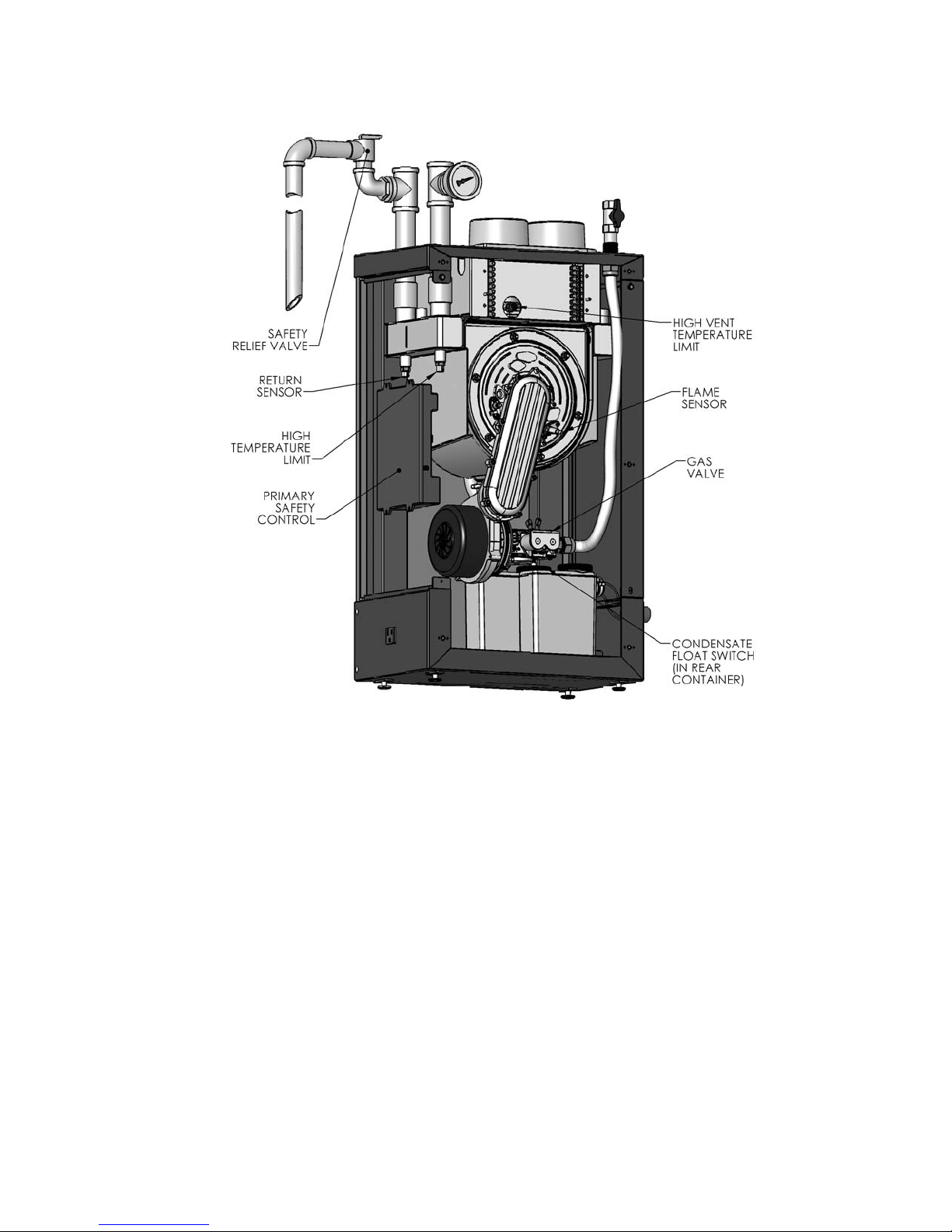
B. The following diagram shows the safety controls and device locations on the appliance. If any one of
these controls or devices are activated, contact a qualified service person immediately. Do not try to
correct the problem without contacting a qualified service person.
1. Primary Safety Control: The primary safety control monitors all limit controls and will prevent
the appliance from operating if a limit has been exceeded. This device also monitors blower
speed and temperature to assure safe operation of the appliance.
2. High Vent Temperature Limit: This device interrupts appliance operation if the vent
temperature exceeds the maximum allowable temperature of the vent material. The control
display module will display “HIGH STACK TEMPERATURE” if this device is activated.
3. High Temperature Limit: This device automatically interrupts boiler operation if the supply
water temperature exceeds 210°degrees Fahrenheit. The primary safety control will not allow
the unit to restart until the reset button is depressed on the display module. The control will
display ”OVERHEAT LIMIT OPEN” if the device is activated.
4. Flame Sensor: The flame sensor monitors the flame and communicates with the primary
safety control to interrupt the gas flow to the appliance if no flame is present. The primary
safety control will lock out if the flame sensor malfunctions producing a false flame signal.
The control will display “IGNITION ERROR, “ “FLAME FAILURE,” or “FALSE FLAME
DETECTED” if this device is activated.
5. Safety Relief Valve: This valve protects the boiler from excessive pressure. This device can
discharge a large amount of hot water and should be piped to discharge near the floor and
away from contact with people. The discharge should be piped near a floor drain if possible.
6. Gas Valve: This valve interrupts the gas flow if no power is present from the primary safety
control.
7. Condensate Float Switch: This device automatically interrupts boiler operation if there is a
blockage in the condensate drain system. The control display module will display “BLOCKED
CONDENSATE DRAIN” if the device is activated.
Page 3
3
C. Instructions for operation and shutting down your boiler are shown on the Operating and Lighting
Instructions Label posted on the back of the boiler cover. The instructions are also shown in Figure 2.
D. The sequence of operation is shown in Figure 3.
Figure 1: Control & Safety Device Locations
Page 4

4
Figure 2: Lighting and Operating Instructions
FOR YOUR SAFETY
READ BEFORE OPERATING
WARNING: If you do not follow these instructions exactly, a fire or explosion
may result causing property damage, personal injury, or loss of life.
A. This appliance does not have a pilot. It is
equipped with an ignition device which
automatically lights the burner. Do not
light the burner by hand.
B. BEFORE OPERATING smell all around the
appliance area for gas. Be sure to smell next
to the floor because some gas is heavier than
air and will settle on the floor.
WHAT TO DO IF YOU DO SMELL GAS
Do not try to light any appliance.
•
Do not touch any electric switch;
•
do not use any phone in your building.
Immediately call your gas supplier from a
neighbor’s phone. Follow the gas supplier’s
instructions.
try to
OPERATING INSTRUCTIONS
1. STOP! Read the safety information above.
2. Set the thermostat to lowest setting.
3. Turn off al l electric power to the appliance.
4. This appliance is equipped with an ignition
device which automatically lights the burner.
Do not try to light the burner by hand.
Gas Control Knob
(show in the “OFF”
position)
If you cannot reach your gas supplier,
call the fire department.
C. Use only your hand to turn the gas control
valve. Never use tools. If the handle will not
turn by hand, don’t try to repair it, call a
qualified service technician. Force or
attempted repair may result in a fire or
explosion.
D. Do not use this appliance if any part has
been under water. Immediat ely call a
qualified service technician to inspect the
appliance and to replace any part of the
control system and any gas control which
has been under water.
5. Turn gas shutoff valve clockwise
Handle will be perpendicular to pipe, do not force.
6. Wait five (5) minutes to clear out any gas.
Then smell for gas, including near the floor.
If you smell gas, STOP ! Follow "B" in the safety
information above on this label. If you don’t smell
gas, go to the next step.
7. Turn gas shutoff valve counterclockwise
to "ON". Handle will be in line with the pipe.
8. Turn on a ll electric power to appliance.
9. Set thermostat to desired setting.
10. If the appliance will not operate, follow the
instructions "To Tur n Off Gas To A ppliance"
and call your service technician or gas supplier.
to "OFF".
TO TURN OFF GA S TO APPLIANCE
1. Set the thermostat to lowest setting.
2. Turn off all electric power to the appliance
if service is to be performed.
(PF)
3. Turn the gas shutoff valve clockwise
Handle will be perpendicular to pipe, do not
force.
9474 REV 0
"OFF".
Page 5

5
6
BLOWER
Figure 3: Sequence of Operation
Page 6

6
User Maintenance
WARNING
Service on this boiler should be undertaken only by trained and skilled personnel from a
qualified service agency. Inspections should be performed at intervals specified in the
Installation, Operation and Maintenance Manual and this User’s Information Manual. Maintain
manuals in a legible condition.
Keep boiler area clear and free of combustible materials, gasoline and other flammable vapors
and liquids.
Do not place any obstructions in boiler room that will hinder flow of combustion and ventilation air.
A. General Housekeeping (Continuous)
1. Keep the area around this appliance clear and free of combustible materials and obstructions.
2. Do not store or use flammable vapors or liquids, such as gasoline, in the vicinity of the boiler.
This applies to any fossil fuel-fired appliance.
3. Do not store or use any sources of hydrocarbons in the vicinity of this appliance.
4. Do not store or use any sources of hydrocarbons in the vicinity of the inlet air termination. If the
source of hydrocarbon contamination cannot be removed, the combustion air must be re-piped
to a different location.
5. Sources of hydrocarbons include bleaches, detergents, cleaning solvents, chlorinated waxes or
cleaners, chlorine based swimming pool chemicals, rock salt or other chloride based ice melt
solutions, water softener salt, refrigerants, paint or varnish removers, fabric softeners,
hydrochloric acid or muratic acid, cements, glues and adhesives.
B. Inspect Venting / Air Inlet System (Monthly)
1. Inspect the vent pipe and assure that it is continuous with no separations, obstructions, sags,
discoloration, depressions or deformation. Vent pipe must be supported at minimum 4 foot
(122 cm) intervals and secured with adhesive specifically formulated for the material used.
2. Air inlet piping must be continuous from the air inlet termination to the boiler with no
separations, obstructions or sags. Air inlet piping must be supported at minimum 4 foot
(122 cm) intervals and secured with adhesive specifically formulated for the material used.
3. Inspect around the vent and air inlet terminations outside the home for obstructions. Keep area
clear of snow and debris. Inspect also for any gaps at the wall penetration(s) which could allow
vented gasses to reenter the home.
4. Notify a qualified service contractor if any problems are found with the venting or air intake
systems and be sure that the problems are corrected.
WARNING
Failure to inspect the venting system and, if problems are found, to notify a qualified service
technician, may result in boiler exhaust entering the structure and causing severe personal
injury or death from carbon monoxide poisoning and oxygen depletion.
Page 7

7
C. Inspect Pressure Relief Valve (Monthly)
1. Inspect the pressure relief valve outlet for signs of leakage.
2. Notify a qualified service contractor immediately if there are signs of leakage. (If the problem
persists, it may be the result of a malfunctioning expansion tank or improper system design).
D. Inspect Condensate Drain System (Monthly)
1. Check the vent hole on the top tee outlet of the condensate drain pipe. Make sure there are no
exhaust emissions leaking from this hole.
2. Check the condensate drain piping for visible water leaks.
3. Check the level of condensate neutralization media (where used) in the front condensate
collector.
4. Notify a qualified service contractor immediately if there are signs of leakage or depleted
neutralization media.
E. Observe Boiler Operation (Monthly)
1. Initiate a call for heat from the system by turning up a room thermostat or draining hot water at
a faucet (if an indirect water heater is used).
2. Observe the boiler start and listen for objectionable noises during the start-up.
3. Contact a qualified service person if objectionable sounds are observed.
F. Control Inspection and Maintenance (As Required by Control Manufacturer)
1. Safety Relief Valve. Conduct try lever test as outlined in manufacturer’s instruction tag on the
safety relief valve.
2. Low Water Cut-off (if used). Follow instructions provided by control manufacturer.
G. General Inspection and Maintenance (Annual)
Annual inspection and service is to be performed by a qualified service contractor as specified in the
Installation, Operation and Maintenance Manual supplied to the installer with the boiler. If a copy of the
original Installation, Operation and Maintenance Manual is not available a new copy is available at
PeerlessBoilers.com or from your local PB Heat Representative.
WARNING
Do not operate the boiler with the condensate drain line disconnected. If there is evidence of
exhaust leakage from the condensate drain line, turn off the unit and contact a qualified service
contractor. These conditions may result in boiler exhaust entering the structure and causing
severe personal injury or death from carbon monoxide poisoning and oxygen depletion.
Page 8

8
H. Error Handling
 Loading...