

PB Heat PSC-06, PSC-05, PSC-04, PSC-03 Installation, Operation & Maintenance Manual
PSC
Boilers
Series
Gas
Installation,
Operation &
Maintenance
Manual

i
USING THIS MANUAL 1
A. INSTALLATION SEQUENCE . . . . . . . . . . . . .1
B. SPECIAL ATTENTION BOXES . . . . . . . . . . . .1
1. PREINSTALLATION 2
A. ACCESSIBILITY CLEARANCES . . . . . . . . . . .2
B. CLEARANCE FROM COMBUSTIBLE
CONSTRUCTION . . . . . . . . . . . . . . . . . . . . . .2
C. INSTALLATION SURVEY . . . . . . . . . . . . . . . .2
D. PLANNING THE LAYOUT . . . . . . . . . . . . . . . .2
2. BOILER SET-UP 3
3. WATER PIPING AND CONTROLS 4
A. BOILER SUPPLY AND RETURN . . . . . . . . . . .4
B. SAFETY RELIEF VALVE . . . . . . . . . . . . . . . . .5
C. PIPING FOR ZONED SYSTEMS . . . . . . . . . . .6
D. EXPANSION TANK . . . . . . . . . . . . . . . . . . . . .7
E. INDIRECT-FIRED WATER HEATER . . . . . . . .7
F. FREEZE PROTECTION . . . . . . . . . . . . . . . . . .7
4. VENTING, VENTILATION AND
AIR INLET 8
A. GENERAL . . . . . . . . . . . . . . . . . . . . . . . . . . . .8
B. PSC WALL THIMBLE . . . . . . . . . . . . . . . . . . .8
C. ROOF TERMINATIONS . . . . . . . . . . . . . . . .10
D. VENT PIPE INSTALLATION . . . . . . . . . . . . .11
E. AIR INLET PIPE INSTALLATION . . . . . . . . .11
F. AIR FOR VENTILATION . . . . . . . . . . . . . . . .12
G. BOILER REMOVAL FROM COMMON
VENTING SYSTEM . . . . . . . . . . . . . . . . . . .12
5. GAS PIPING 13
6. ELECTRICAL 15
A. WIRING . . . . . . . . . . . . . . . . . . . . . . . . . . . . .15
B. ZONED SYSTEM WIRING . . . . . . . . . . . . . .15
C. CONTROLS . . . . . . . . . . . . . . . . . . . . . . . . . .15
D. SEQUENCE OF OPERATION . . . . . . . . . . . .16
7. START-UP PROCEDURES 19
A. COMPLETING THE INSTALLATION . . . . . . .19
B. CONTROL DESCRIPTIONS . . . . . . . . . . . . .22
C. ADJUSTMENT OF GAS PRESSURE
REGULATOR . . . . . . . . . . . . . . . . . . . . . . . . .22
D. CHECKING BURNER INPUT . . . . . . . . . . . . .22
E. CHECK-OUT PROCEDURE . . . . . . . . . . . . . .22
8. TROUBLESHOOTING 24
A. SHUT-DOWN CAUSED BY PILOT OUTAGE,
PRESSURE SWITCH OR FLAME ROLL-OUT
SAFETY SHUT-OFF SWITCH . . . . . . . . . . . .24
B. TROUBLESHOOTING GUIDES . . . . . . . . . .24
C. MEASURING SUCTION PRESSURE . . . . . .24
9. MAINTENANCE 28
A. GENERAL . . . . . . . . . . . . . . . . . . . . . . . . . . .29
B. DAILY (WITH BOILER IN USE) . . . . . . . . . . .29
C. WEEKLY (WITH BOILER IN USE) . . . . . . . . .29
D. MONTHLY (WITH BOILER IN USE) . . . . . . .29
E. ANNUALLY (BEFORE START OF HEATING
SEASON) . . . . . . . . . . . . . . . . . . . . . . . . . . .30
10. BOILER DIMENSIONS & RATINGS 32
11. REPAIR PARTS 33
TABLE OF CONTENTS
1
USING THIS MANUAL
A. INSTALLATION SEQUENCE
Follow the installation instructions provided in this
manual in the order shown. The order of these
instructions has been set in order to provide the installer
with a logical sequence of steps that will minimize
potential interferences and maximize safety during
boiler installation.
B. SPECIAL ATTENTION BOXES
Throughout this manual you will see special attention
boxes intended to supplement the instructions and make
special notice of potential hazards. These categories
mean, in the judgment of PB Heat, LLC:
Indicates special attention is needed, but not directly
related to potential personal injury or property
damage.
NOTICE
Indicates a condition or hazard which will or can
cause minor personal injury or property damage.
CAUTION
DANGER
Indicates a condition or hazard which will cause
severe personal injury, death or major property
damage.
USING THIS MANUAL
Indicates a condition or hazard which may cause
severe personal injury, death or major property
damage.
WARNING
2
PREINSTALLATION
A. ACCESSIBILITY CLEARANCES
Install boiler not less than 24″ (610 mm) between the left
side, top, and front of the boiler and adjacent wall or
other appliance, when access is required for servicing.
B. CLEARANCE FROM COMBUSTIBLE
CONSTRUCTION
The design of this boiler is certified for closet installation
with the following clearances:
1. 6″ (152 mm) between right side, front and
combustible construction.
2. 12″ (305 mm) between top of jacket and
combustible construction.
3. 1″ (25 mm) between left side, rear and combustible
construction.
4. 2″ (51 mm) between vent pipe and combustible
construction.
5. Zero clearance between wall thimble and
combustible construction.
6. This boiler is design certified for use on combustible
flooring.
C. INSTALLATION SURVEY
For new and existing installations, a Water Installation
Survey is available from PB Heat, LLC. The survey will
provide information on how a hot water boiler works
with your specific system and will provide an overview
of hot water system operation in general.
You can also use this survey to locate system problems
which will have to be corrected. To obtain copies of the
Water Installation Survey, contact your PB Heat
representative.
D. PLANNING THE LAYOUT
Prepare sketches and notes of the layout to minimize the
possibility of interferences with new or existing
equipment, piping, venting and wiring. Review
limitations on vent pipe, vent terminal, and air inlet pipe
locations and ventilation air requirements in Section 4.
1. PREINSTALLATION
Read carefully, study these instructions before beginning work.
This boiler must be installed by a qualified contractor.
The boiler warranty can be voided if the boiler is not installed, maintained and serviced correctly.
The equipment must be installed in accordance with those installation requirements of the authority having
jurisdiction or, in the absence of such requirements,to the current edition of the
National Fuel Gas Code,
ANSI
Z223.1/NFPA 54 and/or CAN/CSA B49.1,
Natural Gas and Propane Installation Code
.
Where required by the authority having jurisdiction, the installation must conform to
American Society of Mechanical
Engineers Safety Code for Controls and Safety Devices for Automatically Fired Boilers,
ANSI/ASME CSD-1.
NOTICE
Do not install this boiler on carpeting. Boiler
installation on carpeting is a fire hazard. Install this
boiler on non-combustible flooring or use a
combustible floor pan to install this boiler on other
non-carpeted flooring.
DANGER
Liquefied Petroleum (LP) is heavier than air and may
collect or “pool” in a low area in the event of a leak
from defective equipment.This gas may then ignite,
resulting in a fire or explosion.
WARNING

3
BOILER SET-UP
1. Provide a sound, level foundation. Locate boiler as
near to the outside wall as possible and centralized
with respect to the heating system.
2. Locate boiler in front of installation position before
removing crate.
4. Separate the wood shipping pallet from the boiler
base by removing two (2) hold-down bolts at each
end of the boiler base.
5. Move boiler into final position.
2. BOILER SET-UP
4
WATER PIPING AND CONTROLS
A. BOILER SUPPLY AND RETURN
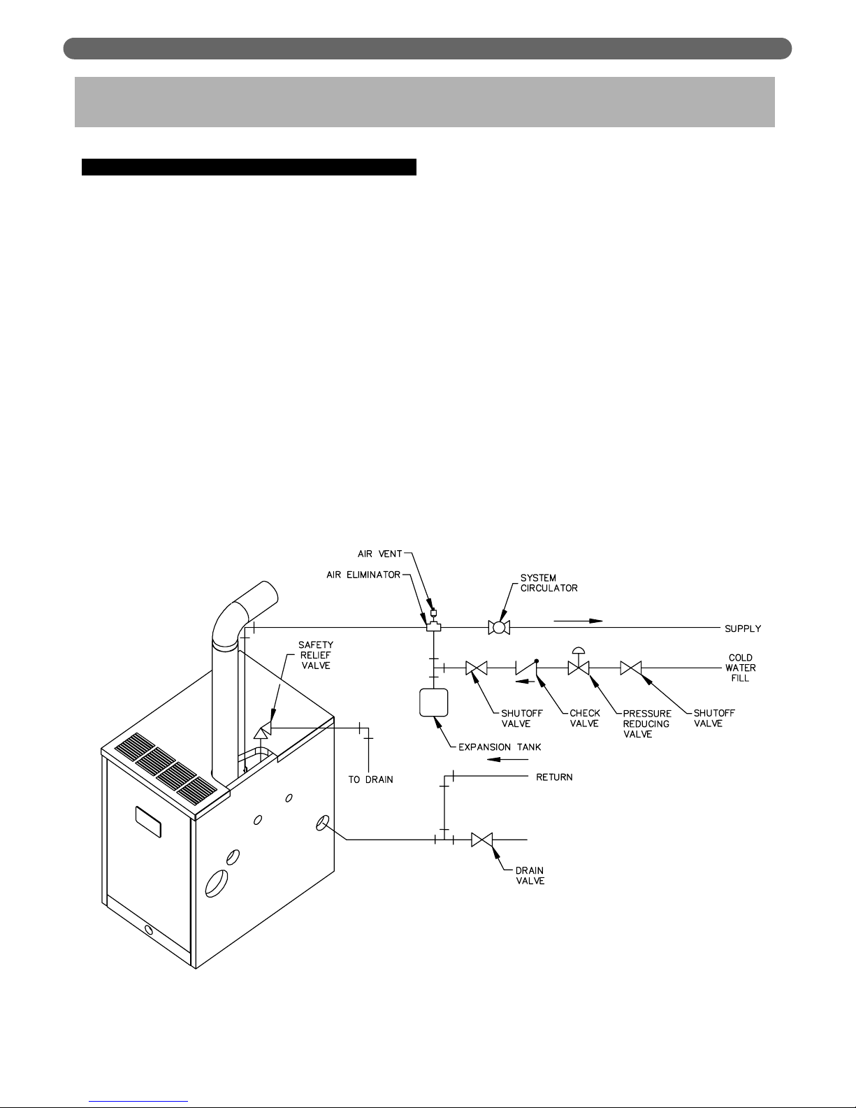
1. Size the supply and return to suit the system. A
typical piping arrangement is shown in Figure 3.1.
Refer also to the Hydronics Institute Residential
Hydronic Heating Installation Design Guide and the
PB Heat Water Survey for additional guidance
during water piping installation.
2. Return Piping:
Pipe the outlet connection of the circulator to a tee,
provided with a drain valve, at the 1-1/4″ NPT return
tapping near the bottom of the right section. Pipe the
return to the inlet connection of the circulator.
3. Supply Piping:
a. Pipe the supply to the 1-1/2″ NPT supply tapping
at the top of the boiler.
b. Provide clearance to venting system
(see Section 4).
4. When system return water temperature will be below
130°F (54°C), pipe the boiler with a bypass
arrangement to blend the system return and hot
supply to obtain at least 130°F (54°C)entering the
boiler. For more information on bypass piping,
consult the PB Heat Water Survey.
5. If desired, install the circulator in the alternate
location shown in Figure 3.1. Consult the PB Heat
Water Survey for more information on circulator
location.
3. WATER PIPING AND CONTROLS
Figure 3.1: Supply and Return Piping
5
WATER PIPING AND CONTROLS
6. Install this boiler so that the gas ignition system
components are protected from water (dripping,
spraying, etc.) during appliance operation and
service (circulator replacement, condensate trap,
control replacements, etc.).
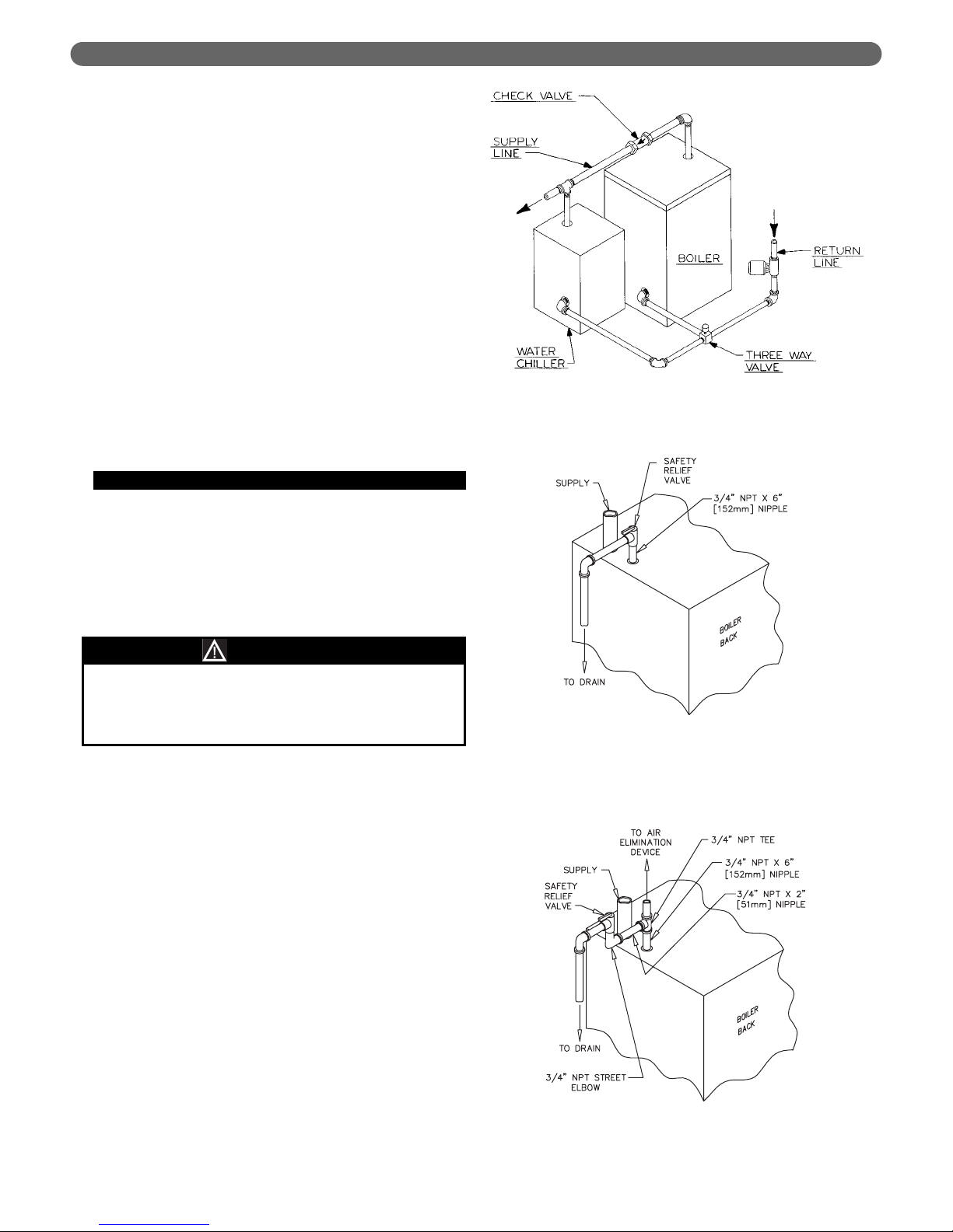
7. If this boiler and distribution system is used in
conjunction with a refrigeration system, pipe the
chilled medium in parallel with the boiler and install
the proper valve to prevent the chilled medium from
entering the boiler. A drawing illustrating this hookup is provided in Figure 3.2.
8. When the boiler is connected to heating coils located
in air handling units where they may be exposed to
refrigerated air circulation, install flow control valves
or other automatic means to prevent gravity
circulation of the boiler water during the cooling
cycle.
9. If this boiler is installed above radiation level,
provide a low water cutoff device, either as a part of
the boiler or at the time of boiler installation.
B. SAFETY RELIEF VALVE
1. Locate safety relief valve and fittings in bag
assembly.
2. If air elimination is not required at the safety relief
valve tapping, install valve and piping as shown in
Figure 3.3.
3. For air elimination at the safety relief valve tapping,
install valve and piping as shown in Figure 3.4.
Pipe the discharge of safety relief valve to prevent
injury in the event of pressure relief. Pipe the
discharge to a drain. Provide piping that is the same
size as the safety relief valve outlet.
CAUTION
Figure 3.4: Safety Relief Valve Hook-Up with
Air Elimination
Figure 3.3: Safety Relief Valve Hook-Up
Installation with Air Elimination in
System Piping
Figure 3.2: Parallel Hook-up with Water Chiller
6
WATER PIPING AND CONTROLS
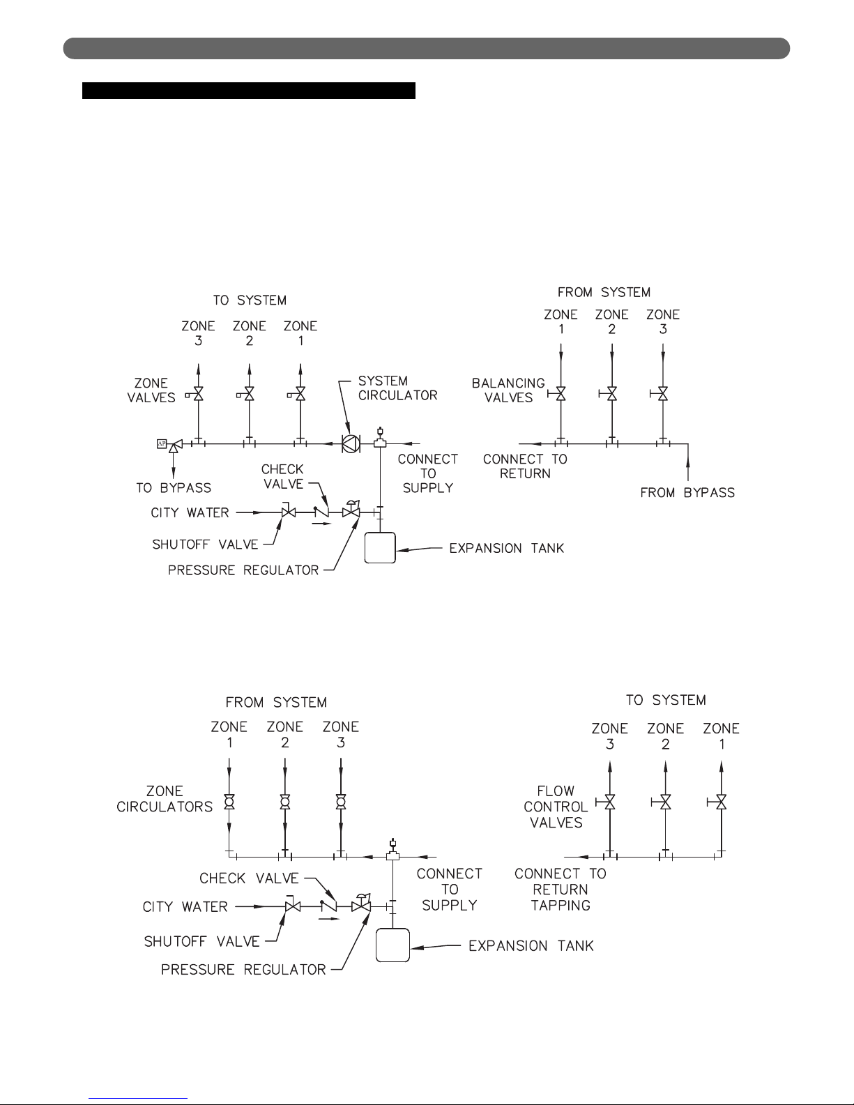
C. PIPING FOR ZONED SYSTEMS
1. See Figures 3.5 and 3.6 for basic zoned system
layouts.
2. Run each zone pipe down then up to zone to
prevent air accumulation in piping.
3. If required, provide means to isolate and drain each
zone separately.
Figure 3.5: Zone Piping with Zone Valves
Figure 3.6: Zone Piping with Circulators
7
WATER PIPING AND CONTROLS
D. EXPANSION TANK
1. Consult the tank manufacturer’s instructions for
specific information relating to tank installation. Size
the expansion tank for the required system volume
and capacity. See Table 10.2 in Section 10 for boiler
water capacity.
2. Expansion tanks are available with built-in fill valves
and check valves for reducing supply water pressure
and maintaining minimum system pressure. Check
the design features of the tank and provide valves as
necessary.
Refer back to Figure 3.1 for typical expansion tank piping.
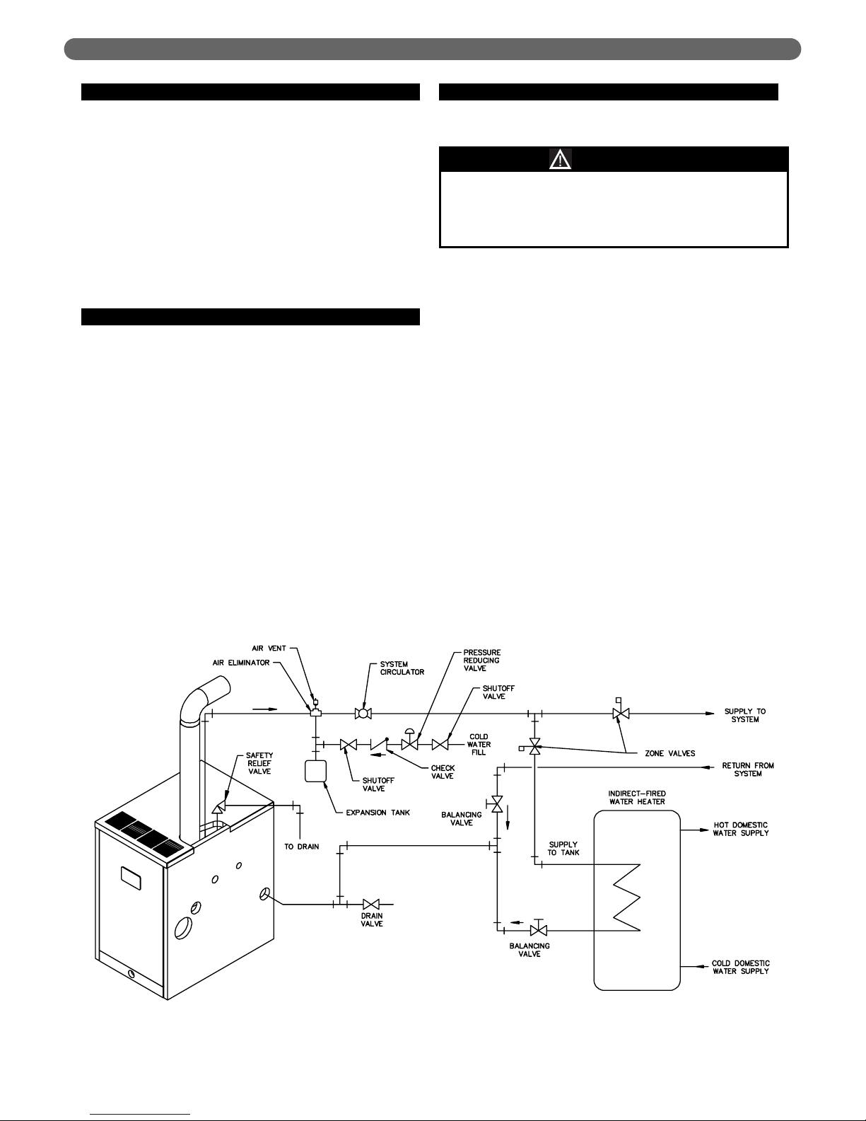
E. INDIRECT-FIRED WATER HEATER
If the boiler is to be used in conjunction with an indirectfired water heater, refer to Figure 3.7 for typical piping.
Follow the instructions provided by the water heater
manufacturer. Pipe the water heater as a separate zone.
F. FREEZE PROTECTION
For new or existing systems that must be freezeprotected:
1. Glycol in hydronic applications is specially
formulated for this purpose. It includes inhibitors
which prevent the glycol from attacking metallic
system components. Make certain that the system
fluid is checked for the correct glycol concentration
and inhibitor level.
2. The glycol solution should be tested at least once a
year and as recommended by the antifreeze
manufacturer.
3. Glycol solutions expand more than water. For
example, a 50% by volume solution expands 4.8%
in volume for a temperature increase from 32°F (0°C)
to 180°F (82°C) , while water expands 3% with the
same temperature rise. Allowance must be made for
this expansion in system design.
4. For more information, consult the PB Heat Water
Installation Survey and the antifreeze manufacturer.
Figure 3.7: Typical Piping with Indirect-Fired Water Heater
Use only inhibited propylene glycol solutions of up to
50% by volume with water. Ethylene glycol is toxic
and can attack gaskets and seals used in hydronic
systems.
WARNING
VENTING, VENTILATION AND AIR INLET
A. GENERAL
Install vent system in accordance with Venting of
Equipment part of the National Fuel Gas Code, ANSI
z223.1/NFPA 54 or sections 7.2, 7.3 or 7.4 of CAN/CSA
B149.1, Natural Gas and Propane Installation Code.
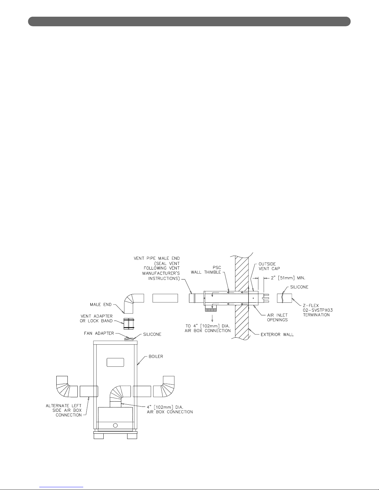
B. PSC WALL THIMBLE (SIDEWALL
VENTING ONLY)
1. Determine vent cap (terminal) location.
a. Must be within the maximum and minimum vent
and air intake lengths shown in Tables 4.1 and 4.2.
b. Maximum wall thickness for the 19-1/2″ (495 mm)
long PSC Wall Thimble (standard) is 11-1/2″ (292
mm). Maximum wall thickness for the optional
28″ (711 mm) long thimble is 20″
(508 mm).
c. Provide 2″ (51 mm) clearance between vent pipe
and combustible construction. No clearance is
required between Thimble and combustible
construction.
d. Provide 3 feet (1 meter) clearance above any
forced air inlet within 10 feet (3 meters).
e. Provide 1 foot (0.3 meters) clearance below, 1 foot
(0.3 meters) beside, or 1 foot (0.3 meters) above
any door, window, or gravity air inlet into any
building.
f. Provide 1 foot (0.3 meters) clearance between
bottom of vent terminal and ground level and
normal snow lines.
g. Provide 4 feet (1.2 meters) horizontal clearance
from from electric meters, gas meters, regulators
and relief equipment. In Canada, this dimension
must be 6 feet (2 meters).
h. Do not locate vent terminal over public walkways
where condensate could create a nuisance or
hazard.
i. When adjacent to a public walkway, locate vent
terminal at least 7 feet (2.1 meters) above grade.
j. Do not locate directly under roof overhangs to
prevent icicles from forming.
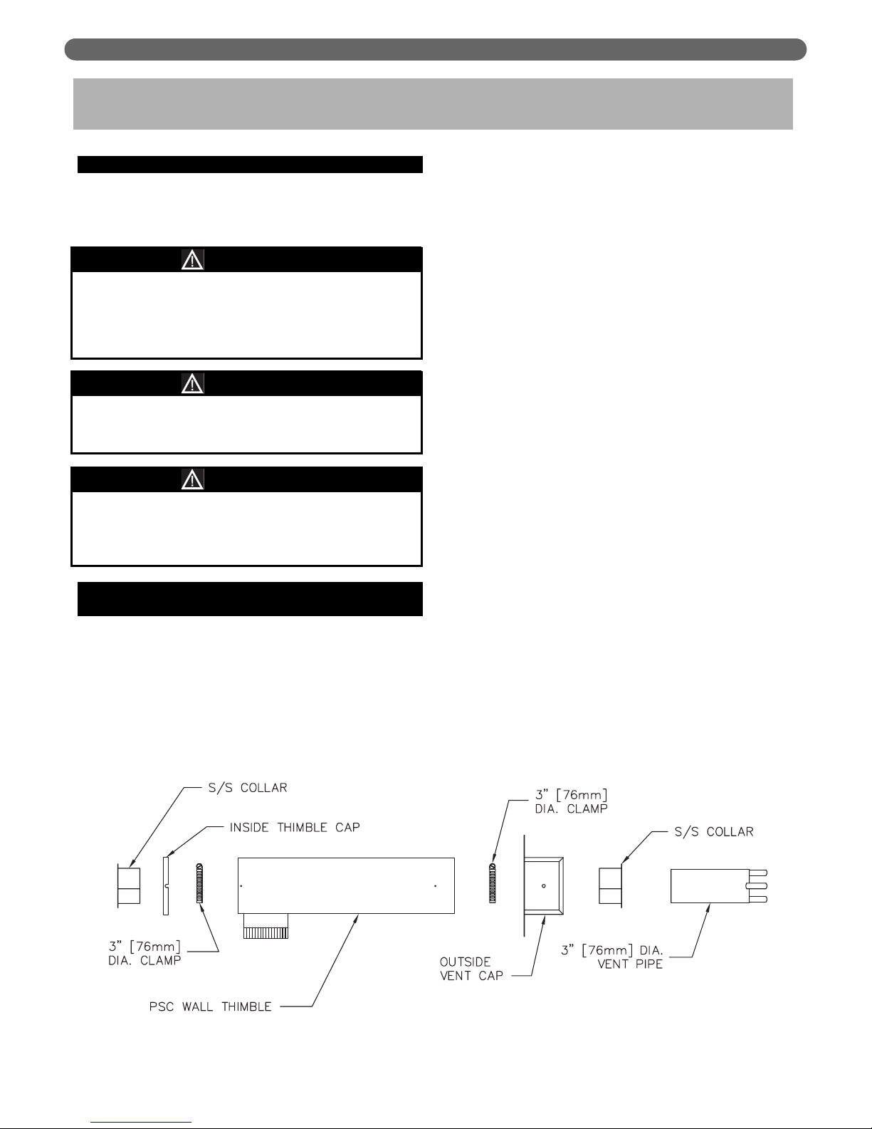
2. Cut a 5-1/8″ (130 mm) square hole in sidewall to
allow Peerless Wall Thimble to go through.
3. Insert Thimble from inside wall with 4″ (102 mm)
diameter air inlet connection facing down. Extend
Thimble 3-1/2″ (89 mm) past outside wall surface.
The cut-out opening of thimble is pointed down.
4. Use a minimum 2-1/2 foot (762 mm) piece of 3″
(76 mm) diameter AL29-4C stainless steel vent pipe
for insertion through Wall Thimble. See Vent Pipe
section below for vent pipe requirements.
4. VENTING
Figure 4.1: PSC Wall Thimble
This vent system will operate with a positive
pressure in the vent pipe. Do not connect vent
connectors serving appliances vented by natural
draft into any portion of mechanical draft systems
operating under positive pressure.
Flue gases will condense as they exit the vent
termination.This condensate can freeze on exterior
building surfaces which may cause discoloration of
these surfaces.
NOTICE
WARNING
WARNING
All joints of positive pressure vent systems must be
sealed completely to prevent leakage of flue products
into the living space.
8
VENTING, VENTILATION AND AIR INLET
5. Slide Stainless Steel Collar over vent pipe and slide
3″ (76 mm) diameter hose clamp and collar to vent
pipe.
6. Insert pipe with collar through Outside Vent Cap and
slide 3″ (76 mm) diameter hose clamp and collar to
vent pipe.
7. Leave at least 2″ (51 mm) of vent pipe protruding
beyond face of Vent Cap and secure hose clamp and
collar to vent pipe.
8. Place Outside Vent Cap over Wall Thimble with air
openings in Vent Cap facing down. Secure Cap to
Thimble with #10 sheet metal screws.
9. Place 3″ (76 mm) diameter hose clamp over pipe
protruding through inside of Wall Thimble.
10. Place Inside Thimble Cap and Collar onto Wall
Thimble. Access hose clamp through 4″ (102 mm)
diameter collar on bottom of Thimble and secure hose
clamp over collar and vent pipe as per step 7 above.
11. Secure Inside Thimble cap to Wall Thimble with #10
screws. Seal Thimble Cap perimeter with silicone.
12. Seal all openings between Wall and Thimble and
around the 3″ (76 mm) diameter stainless steel vent
pipe that protrudes through inside and outside of
Wall Thimble.
13. Add any bracing that may be needed to support Wall
Thimble on inside of wall structure.
14. Secure Outside Vent Cap to exterior wall with four
#10 sheet metal screws provided.
15. Attach Z-Flex #2SVSTPF03 terminal to protruding
vent pipe. Refer to Figure 4.2. To attach to HEATFAB pipe, insert into pipe end and fold over tabs to
secure. Otherwise, silicone terminal to vent pipe.
Figure 4.2: Side Wall Venting System
9
10
VENTING, VENTILATION AND AIR INLET
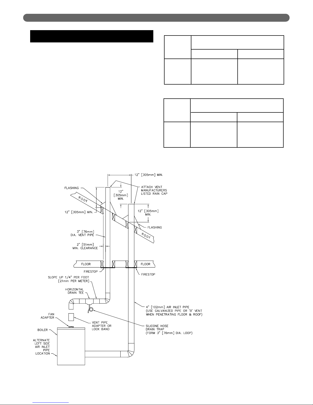
C. ROOF TERMINATIONS (VERTICAL
VENTING)
1. Vent pipe and air inlet terminations must be within
the maximum and minimum vent and air intake
lengths shown in Tables 4.1 and 4.2.
2. Vent pipe and air inlet pipe must terminate 12"
(305 mm) above expected snow lines. Vent pipe
must be a minimum 12" (305 mm) above and 12"
(305 mm) horizontally from air inlet pipe. See Figure
4.3.
3. Attach a vent manufacturer's listed rain cap to both
the vent pipe and air inlet pipe.
4. Provide 2" (51 mm) clearance between vent pipe
and combustible construction. No clearance is
required between air inlet pipe and combustible
construction.
5. See vertical venting section in vent manufacturer's
instructions for recommendations for penetration
through roof.
52 feet (15.5 m)
52 feet (15.5 m)
45 feet (13.5 m)
45 feet (13.5 m)
PSC-03
PSC-04
PSC-05
PSC-06
Boiler Model
8 feet (2.5 m)
8 feet (2.5 m)
8 feet (2.5 m)
8 feet (2.5 m)
Table 4.1:
*Equivalent Length of 3″ (76 mm) Diameter
Stainless Steel Vent Pipe
Minimum Vent Length
Maximum Vent Length
70 feet (21.0 m)
70 feet (21.0 m)
63 feet (19.0 m)
63 feet (19.0 m)
PSC-03
PSC-04
PSC-05
PSC-06
Boiler Model
12 feet (4.0 m)
12 feet (4.0 m)
12 feet (4.0 m)
12 feet (4.0 m)
Table 4.2:
*Equivalent Length of 4″ (102 mm) Diameter
Aluminum/Galvanized Air Inlet Pipe
Minimum Length
Maximum Length
*Each 90° elbow equals 5 feet (1.5 meters) of equivalent
length.
Figure 4.3: Vertical Venting System
 Loading...