

Page 1

Boiler
Peerless
®
Gas
Installation,
Operation &
Maintenance
Manual
Combi 160
™
INSTALLER, THESE INSTRUCTIONS TO BE AFFIXED ADJACENT TO THE BOILER.
WARNING!!!
This manual must
be used by a
qualified heating
installer/service
technician. Read all
instructions,
including this
manual, before
installing. Perform
steps in the order
given. Failure to
comply could result
in severe personal
injury, death, or
substantial property
damage.
Save this manual for
future reference.
As an ENERGY STAR®Partner, PB Heat, LLC has determined that
this product meets the ENERGY STAR guidelines for energy efficiency.
Page 2
SAFETY INSTRUCTIONS
WARNING: If the information in these
instructions is not followed exactly, a fi re
or explosion may result causing property
damage, personal injury or death.
- Do not store or use gasoline or other
fl ammable vapors and liquids in the
vicinity of this or any other appliance.
- WHAT TO DO IF YOU SMELL GAS
• Do not try to light any appliance.
• Do not touch any electrical switch; do
not use any phone in your building.
• Immediately call your gas supplier from
a neighbor’s phone. Follow the gas
supplier’s instructions.
• If you cannot reach your gas supplier,
call the fi re department.
- Installation and service must be performed
by a qualifi ed installer, service agency or
the gas supplier.
AVERTISSMENT: Assurez vous de bien
suivre les instructions données dans
cette notice pour réduire au minimum
le risque d’incendie ou d’explosion ou
pour éviter tout dommage matériel, toute
blessure ou la mort
- Ne pas entreposer ni utiliser d’essence
ou ni d’autres vapeurs ou liquides
infl ammables à proximité de cette appareil
ou de tout autre appareil.
- QUE FAIRE SI VOUS SENTEZ UNE ODEUR
DE GAZ:
• Ne pas tenter d’allumer l’appareil.
• Ne touchez à aucun interrupteur, ne
pas vous servir des téléphones se
trouvant dans le bâtiment
• Appelez immédiatement votre
fournisseur de gas de puis un voisin.
Suivez les instructions du fournisseur.
• Si vous ne pouvez rejoindre le
fournisseur, appelez le service des
incendies
- L’installation et l’entretien doivent être
assurés par un installateur ou un service
d’entretien qualifi é ou par le fournisseur
de gaz.
2
Page 3
SAFETY INSTRUCTIONS
3
Page 4

SAFETY INSTRUCTIONS
WARNING!!! These instructions must be read
prior to installation. If the information in these
instructions is not followed exactly, a fi re or
explosion may result, causing property damage,
personal injury, or death.
Liability
The manufacturer declines all liability, contractual or
otherwise, for damages resulting from the incorrect
installation of this boiler. This includes the failure
to comply with the instructions provided by the
manufacturer or from a failure to comply with the
applicable local and national regulations in force.
The manufacturer declines all liability, contractual
or otherwise, for any damage to people, animals or
property caused by the incorrect use of this boiler or
inadequate or incorrect service or maintenance.
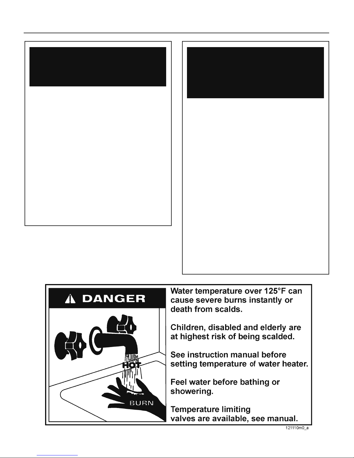
Hazards and Your Safety - Hot Water Can Scald!
Water temperature over 125°F (52°C) can cause
severe burns instantly, or death from scalds. Children,
the disabled, and the elderly are at highest risk of
being scalded; see instruction manual before setting
temperature at boiler! Feel water before bathing or
showering.
If there is a smell of combustion products, turn the
unit off, air out the room and call a licensed authorized
technician. Failure to take proper precautions can
result in excessive levels of carbon monoxide which
can cause severe personal injury or death!
Qualifi ed Technicians:
Qualifi ed technicians are individuals with specifi c,
technical training in space heating systems, domestic
hot water systems, fuel gas systems and electrical
systems. These individuals must have the legally
required qualifi cations.
Installation and Alterations:
Licensed, authorized personnel must carry out the
installation and calibration of the boiler. Never modify
the boiler or its fl ue gas carrying components in any
way. This boiler must be properly vented. Failure to
follow these instructions could result in personal injury
or death!
For safety and environmental reasons, the packing
materials must be properly disposed of. Any replaced
part or packaging should never be left within the reach
of children. Failure to follow these instructions could
result in severe personal injury
In the event of a breakdown and/or malfunction
of the boiler, turn off the unit and do not make any
attempt to repair it. The boiler must be serviced
exclusively by a qualifi ed technician using original
spare parts. Failure to comply with this requirement
may compromise the safety of the unit and void its
warranty.
Use the service switch to disconnect the boiler
from the electrical circuit before carrying out any
service or maintenance operations.
Electrical
CAUTION: Label all wires prior to disconnection when
servicing controls. Wiring errors can cause improper
and dangerous operation. Verify proper operation after
servicing.
ATTENTION: Au moment de l’entretien des
commandes, étiquetez tous les fi ls avant de les
débrancher. Des erreurs de câblage peuvent entraîner
un fonctionnement inadéquat et dangereux. S’assurer
que l’appareil fonctionne adéquatement une fois
l’entretirn terminé.
Correct Use:
This boiler must only be used for the purpose for which
it has been expressly designed: heating of water for
closed circuit systems for central heating and the
production of domestic hot water.
Should overheating occur or the gas supply fail
to shut off, do not turn off or disconnect the electrical
supply to the pump. Instead, shut off the gas supply at
a location external to the appliance.
En cas de surchauffe ou si l’alimentation de gaz
ne peut être coupée, ne pas couper ni débranch
l’alimentation électrique de la ponpe. Fermer plutôt le
robinet d’admission de gaz à l’extérieur de l’appareil
Do not use this appliance if any part has been
under water. Immediately call a qualifi ed service
technician to inspect the appliance and to replace any
part of the control system and any gas control, which
has been under water.
N’utilisez pas cet appareil s’il a été plongé dans
l’eau, même partiellement. Faites inspecter l’appareil
par un tecnicien qualifi é et remplacez toute partie du
système de contrôle et toute commande qui ont été
plongés dans l’eau.
Do not obstruct the air intake or vent pipe
terminals. Failure to take proper precautions can
result in excessive levels of carbon monoxide which
can cause severe personal injury or death!
Maintenance:
At least once a year the user must call in a licensed
authorized technician for routine maintenance.
Any optional extras or kit fi tted subsequently
must be original Cosmogas parts.
4
Page 5

SAFETY INSTRUCTIONS
Local approval: of the fl ue system and the
condensate connection to the public sewer system may
be required.
Local approval: The local building regulations
stipulating the installation rules at the time of installation
should be followed.
Defects: If you fi nd any defects you must inform the
owner of the system of the defect and associated hazard
in writing.
When servicing the boiler, to avoid severe burns,
allow the boiler to cool before performing maintenance.
When calling or writing about the boiler- Please
have the boiler model and serial number from the boiler
rating plate.
Any claims for damage or shortage in shipment
must be fi led immediately against the transportation
company by the consignee.
Factory warranty (shipped with unit) does
not apply to units improperly installed or improperly
operated.
5
Page 6

TABLE OF CONTENTS
SAFETY INSTRUCTIONS ................................................................................................................................................ 2
TABLE OF CONTENTS ....................................................................................................................................................6
1 - INSTALLATION - CODE REQUIREMENTS .............................................................................................................. 10
1.1 - National installation legislation ...........................................................................................................................10
1.2 - Commonwealth of Massachusetts Installation Requirements ............................................................................10
2 - GENERAL INFORMATION ........................................................................................................................................ 12
2.1 - Key to symbols used ..........................................................................................................................................12
2.2 - Description of the Peerless
3 - MAIN COMPONENTS ............................................................................................................................................... 13
4 - FUNCTION OVERVIEW ............................................................................................................................................ 15
4.1 - Intended use and functions of the boiler ...........................................................................................................16
4.2 - Setting of the boiler ............................................................................................................................................16
4.3 - Effi ciency up to 98% ...........................................................................................................................................17
4.4 - Characteristic curves of heating system’s residual head ...................................................................................18
4.5 - Characteristic curve of the domestic side ..........................................................................................................18
5 - INSTALLATION - Mounting & gas and water connections ................................................................................... 19
5.1 - Clearances for installation and servicing ............................................................................................................19
5.2 - Clearances from combustible material ...............................................................................................................19
5.3 - Choosing the installation location .......................................................................................................................20
5.4 - Mounting the boiler .............................................................................................................................................21
5.5 - Gas and water connections ................................................................................................................................21
5.6 - Condensate disposal ..........................................................................................................................................22
5.7 - Near boiler heating piping components ..............................................................................................................22
5.8 - Relief valve .........................................................................................................................................................23
5.9 - Supply and return piping ....................................................................................................................................23
5.9.1 - Converting a combi boiler into a heating only boiler .............................................................................24
5.10 - Low temperature heating systems ...................................................................................................................24
5.11 - Use of glycol and other chemicals ....................................................................................................................24
5.12 - Domestic hot and cold water ............................................................................................................................24
5.13 - Gas supply piping .............................................................................................................................................24
5.14 - Propane gas .....................................................................................................................................................25
5.15 - Operating at high altitudes ...............................................................................................................................25
5.16 - Convert the boiler from Natural Gas to Propane Gas or vice versa .................................................................26
5.17 - Suggested piping and wiring connections ........................................................................................................28
6 - INSTALLATION - Electrical connections ................................................................................................................29
6.1 - Electrical connections: overview ........................................................................................................................29
6.2 - Connecting the power supply cable ...................................................................................................................30
6.3 - Choosing the room thermostat ...........................................................................................................................30
6.4 - Thermostat wiring ...............................................................................................................................................30
6.5 - Installing the outdoor temperature sensor (optional) ..........................................................................................31
6.6 - Alarm output .......................................................................................................................................................31
7 - INSTALLATION - Indirect storage tank connections .............................................................................................32
7.1 - Connecting the boiler to an indirect storage tank ..............................................................................................32
7.2 - Indirect water heater priority selection ..............................................................................................................33
8 - INSTALLATION - Vent & combustion air ................................................................................................................ 34
8.1 - Removing of a boiler from a common venting system .......................................................................................34
8.2 - Venting systems .................................................................................................................................................35
8.3 - Design of the venting system .............................................................................................................................37
8.4 - Prevent Combustion air contamination ..............................................................................................................37
8.5 - Install Vent and Combustion air piping ...............................................................................................................37
®
Combi 160™: .........................................................................................................12
6
Page 7

TABLE OF CONTENTS
8.6 - Air inlet pipe materials ........................................................................................................................................39
8.6.1 - Sealing of Type “B” double-wall or galvanized air inlet pipe material ....................................................39
8.6.2 - Sealing of PVC, CPVC or ABS air inlet pipe .........................................................................................39
8.7 - PVC/CPVC vent piping materials .......................................................................................................................40
8.7.1 - Installing PVC/CPVC vent and air piping ..............................................................................................40
8.7.2 - PVC/CPVC air intake/vent connections ................................................................................................40
8.8 - Flue terminal location in compliance with CAN/CSA B149 ................................................................................42
8.9 - Single pipe vent (not sealed combustion) ..........................................................................................................43
8.9.1 - Combustion Air and Ventilation openings .............................................................................................43
8.9.2 - Determine location ................................................................................................................................44
8.10 - Sidewall termination - Two pipes ......................................................................................................................45
8.10.1 - Vent/air termination .............................................................................................................................45
8.10.2 - Determine location ..............................................................................................................................45
8.10.3 - Prepare wall penetrations ...................................................................................................................47
8.10.4 - Termination and fi ttings .......................................................................................................................47
8.10.5 - Multiple vent/air terminations ..............................................................................................................47
8.11 - Sidewall termination - Concentric vent ............................................................................................................. 48
8.11.1 - Description and usage ........................................................................................................................48
8.11.2 - Sidewall termination installation .......................................................................................................... 48
8.11.3 - Multiventing sidewall terminations .......................................................................................................49
8.12 - Vertical termination - Two pipes ....................................................................................................................... 50
8.12.1 - Determine location ..............................................................................................................................50
8.12.2 - Prepare roof penetrations ...................................................................................................................50
8.12.3 - Termination and fi ttings .......................................................................................................................50
8.12.4 - Multiple vent/air terminations ..............................................................................................................51
8.13 - Vertical termination - Concentric vent ..............................................................................................................52
8.13.1 - Description and usage ........................................................................................................................52
8.13.2 - Determine location ..............................................................................................................................52
8.13.3 - Vertical termination installation ...........................................................................................................52
8.13.4 - Multiventing vertical terminations ........................................................................................................53
8.13.5 - Alternate vertical concentric venting ...................................................................................................54
8.14 - Existing vent as a chase ..................................................................................................................................55
9 - INSTALLATION - Split venting system ...................................................................................................................56
9.1 - Split system (polypropylene) or AL29-4C (UL 1738/UL C 636) system .............................................................56
9.2 - Split system components ...................................................................................................................................58
9.3 - Split system components ...................................................................................................................................59
9.4 - Split system: installation examples ....................................................................................................................60
10 - INSTALLATION - Coaxial venting system ............................................................................................................61
10.1 - Coaxial system .................................................................................................................................................61
10.2 - Coaxial system components ............................................................................................................................62
10.3 - Coaxial system components ............................................................................................................................63
10.4 - Coaxial system: installation examples .............................................................................................................64
11 - OPERATING ............................................................................................................................................................65
11.1 - Operating ..........................................................................................................................................................65
11.1.1 - User instructions .................................................................................................................................65
11.1.2 - Filling the condensate trap .................................................................................................................. 65
11.1.3 - Filling the heating system ....................................................................................................................65
11.1.4 - Filling the domestic hot water heat exchanger ....................................................................................66
11.1.5 - Auto-purging the heating system ......................................................................................
...................66
7
Page 8

TABLE OF CONTENTS
11.2 - General warnings concerning gas supply ........................................................................................................66
11.3 - Confi rming the boiler’s gas type .......................................................................................................................66
11.4 - Gas type conversion .........................................................................................................................................66
11.5 - Start-up .............................................................................................................................................................66
11.6 - Ignition control testing ......................................................................................................................................67
11.7 - Gas supply pressure checking and adjustment ................................................................................................67
11.8 - Check the combustion air pressure ..................................................................................................................68
11.9 - Checking and adjusting CO2 levels .................................................................................................................69
11.10 - Adjusting the heating capacity ........................................................................................................................70
11.11 - Domestic hot water fl ow rate adjustment ........................................................................................................70
11.12 - Cold start boiler ..............................................................................................................................................70
12 - USE ..........................................................................................................................................................................71
12.1 - Check heating system pressure .......................................................................................................................71
12.2 - Overview ..........................................................................................................................................................71
12.3 - Displays ............................................................................................................................................................71
12.4 - Start-up procedure ...........................................................................................................................................72
12.5 - Summer mode ..................................................................................................................................................72
12.6 - Winter mode .....................................................................................................................................................72
12.7 - Adjusting the domestic hot water temperature .................................................................................................73
12.8 - Heating system temperature adjustment .........................................................................................................73
12.9 - Heating system type selection .........................................................................................................................73
12.10 - Outdoor reset adjustment ...............................................................................................................................73
12.10.1 - Outdoor reset applications ................................................................................................................73
12.10.2 - Outdoor reset adjustment precautions ..............................................................................................74
12.10.3 - Outdoor reset: setting parameters ....................................................................................................74
12.10.4 - Outdoor reset: zone adjustments ......................................................................................................74
12.10.5 - Outdoor reset activation ....................................................................................................................74
12.10.6 - Outdoor reset with room compensation ............................................................................................74
12.11 - Boiler switch settings ......................................................................................................................................76
12.12 - Delays, alarms and protective actions ...........................................................................................................76
12.13 - Circulator pump and three way valve protection ............................................................................................76
12.14 - Freeze protection ...........................................................................................................................................76
12.15 - Display in energy saving mode .....................................................................................................................76
12.16 - “Users’ menu” .................................................................................................................................................77
12.17 - “Installer’s menu” ............................................................................................................................................78
12.18 - Diagnostics .....................................................................................................................................................80
12.18.1 - Diagnostics: “L” lock-outs ..................................................................................................................81
12.18.2 - Diagnostics: “E” blocking errors ........................................................................................................83
13 - MAINTENANCE .......................................................................................................................................................85
13.1 - General precaution ...........................................................................................................................................85
13.2 - Removing the casing ........................................................................................................................................86
13.3 - Cleaning the burner and primary heat exchanger, fl ue gas side ...................................................................... 87
13.4 - Correct positioning of the ignition and fl ame detection electrodes ..................................................................88
13.5 - Domestic hot water heat exchanger .................................................................................................................88
13.6 - Condensate trap cleaning ................................................................................................................................89
13.7 - Circulator pump motor replacement .................................................................................................................90
13.8 - Expansion tank pressure ..................................................................................................................................90
13.9 - 3-way valve removal ........................................................................................................................................91
13.10 - Draining the heating side of the boiler ............................................................................................................92
13.11 - Draining the domestic hot water side of the boiler .........................................................................................92
8
Page 9

TABLE OF CONTENTS
13.12 - Overrides ........................................................................................................................................................92
13.12.1 - Auto-purging ......................................................................................................................................92
13.12.2 - Fan ...................................................................................................................................................92
13.12.3 - Minimum and maximum output .........................................................................................................92
13.12.4 - Checking the fl ame current ...............................................................................................................92
13.13 - Water and fl ue temperature sensor ................................................................................................................93
13.14 - Outdoor temperature sensor (optional) ..........................................................................................................93
13.15 - Functional wiring diagram ..............................................................................................................................94
13.16 - Multiwire wiring diagram .................................................................................................................................96
14 - TECHNICAL DATA .................................................................................................................................................. 98
15 - SPARE PARTS ........................................................................................................................................................99
16 - READ OUT FLOW CHART ...................................................................................................................................102
9
Page 10

1 - INSTALLATION - CODE REQUIREMENTS
1.1 - National
installation
legislation
- The installation must conform to the
requirements of the authority having
jurisdiction or, in the absence of such
requirements, to the latest edition of
the National Fuel Gas Code, ANSI
Z223.1/NFPA 54 and or CAN/CSA
B149.1, Natural Gas and Propane
Installation Code.
- Where required by the authority
having jurisdiction, the installation
must conform to the Standard for
Controls and Safety Devices for
Automatically Fired Boilers, ANSI/
ASME CSD-1.
NOTICE!
This boiler meets the safety and
other performance requirements as
specifi ed in ANSI Z21.13 standard
- Per DOE mandate, the operator
control incorporates an automatic
means (outdoor reset) of adjusting
the boiler hot water temperature for
hot water heating. The boiler must not
operate without the automatic means
enabled.
IMPORTANT!
In accordance with Section 325 (f)(3)
of the energy policy and conservation
Act, this boiler is equipped with a
feature that saves energy by reducing
the boiler water temperature as the
heating load decreases. This feature
is equipped with an override which is
provided primarily to permit the use
of an external management system
that serves the same function. THIS
OVERRIDE MUST NOT BE USED
UNLESS AT LEAST ONE OF THE
FOLLOWING CONDITIONS IS
TRUE:
An external energy management
system is installed that reduces
the boiler water temperature as the
heating load decreases.
This boiler is not used for any
space heating.
This boiler is part of a modular
multiple boiler system having a total
input of 300,000 BTU/hr or greater.
This boiler is equipped with a
tankless coil.
1.2- Commonwealth
of Massachusetts
Installation
Requirements
In the Commonwealth of
Massachusetts, the installation
must be performed by a licensed
plumber or gas fi tter. WARNING!!!
WARNING!!! Improper
venting can result in excessive
levels of carbon monoxide
which can cause severe
personal injury or death!
(a) For all side wall horizontally
vented gas fueled equipment
installed in every dwelling, building
or structure used in whole or in
part for residential purposes,
including those owned or operated
by the commonwealth and
where the side wall exhaust vent
termination is less than seven (7)
feet above fi nished grade, in the
area of the venting, including but
not limited to decks and porches,
the following requirements shall be
satisfi ed:
1. INSTALLATION OF CARBON
MONOXIDE DETECTORS. At
the time of installation of the side
wall horizontal vented gas fueled
equipment, the installing plumber
or gasfi tter shall observe that
a hard wired carbon monoxide
detector with an alarm and battery
back-up is installed on the fl oor
level where the gas equipment
is to be installed. In addition, the
installing plumber or gasfi tter shall
observe that a battery operated
or hard wired carbon monoxide
detector with an alarm is installed
on each additional level of the
dwelling, building or structure
served by the side wall horizontal
vented gas fueled equip-ment.
It shall be the responsibility of
the property owner to secure the
services of qualifi ed licensed
professionals for the installation
of hard wired carbon monoxide
detectors.
10
a. In the event that the side wall
horizontally vented gas fueled
equipment is installed in a crawl
space or an attic, the hard wired
carbon monoxide detector with
alarm and battery back-up may
be installed on the next adjacent
fl oor level.
b. In the event that the
requirements of this subdivision
can not be met at the time
of completion of installation,
the owner shall have a period
of thirty (30) days to comply
with the above requirements;
provided, however, that during
said thirty (30) day period,
a battery operated carbon
monoxide detector with an
alarm shall be installed.
2. APPROVED CARBON
MONOXIDE DETECTORS. Each
carbon monoxide detector as
required in accordance with the
above provisions shall comply with
NFPA 720 and be ANSI/UL 2034
listed and IAS certifi ed.
3. SIGNAGE. A metal or plastic
identifi cation plate shall be
permanently mounted to the
exterior of the building at a
minimum height of eight (8) feet
above grade directly in line with
the exhaust vent terminal for the
horizontally vented gas fueled
heating appliance or equipment.
The sign shall read, in print size
no less than one-half (1/2) inch
in size, “GAS VENT DIRECTLY
BELOW. KEEP CLEAR OF ALL
OBSTRUCTIONS”.
4. INSPECTION. The state or local
gas inspector of the side wall
horizontally vented gas fueled
equipment shall not approve
the installation unless, upon
inspection, the inspector observes
carbon monoxide detectors and
signage installed in accordance
with the provisions of 248 CMR
5.08(2)(a)1 through 4.
Page 11

1 - INSTALLATION - CODE REQUIREMENTS
(b) Exemptions
The following equipment is exempt
from 248 CMR 5.08(2)(a) 1 through
4:
1. The equipment listed in Chapter
10 entitled “Equipment Not
Required To Be Vented” in the
most current edition of NFPA 54
as adopted by the Board; and
2. Product Approved side wall
horizontally vented gas fueled
equipment installed in a room
or structure separate from the
dwelling, building or structure used
in whole or in part for residential
purposes.
(c) MANUFACTURER
REQUIREMENTS - GAS
EQUIPMENT - VENTING SYSTEM
PROVIDED.
When the manufacturer of Product
Approved side wall horizontally vented
gas equipment provides a venting
system design or venting system
components with the equipment,
the instructions provided by the
manufacturer for installation of the
equipment and the venting system
shall include:
1. Detailed instructions for the
installation of the venting system
design or the venting system
components; and
2. A complete parts list for the
venting system design or venting
system.
(e) A copy of all installation
instructions for all Product
Approved side wall horizontally
vented gas fueled equipment, all
venting instructions, all parts lists
for venting instructions, and/ or
all venting design instructions
shall remain with the appliance or
equipment at the completion of the
installation.
(d) MANUFACTURER
REQUIREMENTS – GAS
EQUIPMENT - VENTING SYSTEM
NOT PROVIDED.
When the manufacturer of a Product
Approved side wall horizontally
vented gas fueled equipment does not
provide the parts for venting the fl ue
gases, but identifi es “special venting
systems”, the following requirements
shall be satisfi ed by the manufacturer:
1. The referenced “special venting
system” instructions shall be
included with the appliance or
equipment installation instructions;
and
2. The “special venting systems”
shall be Product Approved by
the Board, and the instructions
for that system shall include a
parts list and detailed installation
instructions.
11
Page 12
2 - GENERAL INFORMATION
2.1 - Key to
symbols used
WARNING!!! Failure to follow
these indications can causing
an explosion, extensive property
damage, severe personal injury or
death!
CAUTION!!!
Electrical caution! Risk of electric
shock: failure to observe this warning
may compromise the smooth running
of the appliance or cause serious
damage to individuals, animals or
property.
CAUTION!!!
General caution. Failure to observe
this warning may compromise the
smooth running of the appliance or
cause serious damage to individuals,
animals or property.
Operation symbol
Important indication symbol
2.2 - Description
of the Peerless®
™
Combi 160
Combi version (space heating and
instantaneous D.H.W. production).
Modulating gas-fi red, condensing hot
water boiler, with sealed combustion
chamber and pre-mix burner, with
maximum power input of 160,000 Btu/
hr (47 kW) and minimum of 30,000
Btu/hr (9 kW)
:
12
Page 13
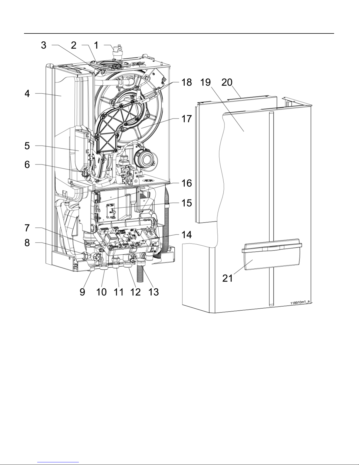
3 - MAIN COMPONENTS
1 - Automatic air vent
2 - Air intake and fl ue gas discharge fi tting (venting system)
3 - U7 fl ue gas temp. sensor and fl ue safety switch
4 - Expansion tank
5 - Inlet air plenum
6 - Air/gas mixer device
7 - U2 d.h.w. temp. sensor
8 - Heating pressure switch (low water cut-off)
9 - Heating supply connection
10 - DHW connection
11 - Gas inlet connection
12 - Cold water connection
Figure 1 - Main components
13 - Heating return connection
14 - Power Control Board
15 - Openterm interface board (optional)
16 - Connection board
17 - Primary heat exchanger
18 - Spark cable
19 - External jacket
20 - Combustion chamber door
21 - Instrument panel door
13
Page 14
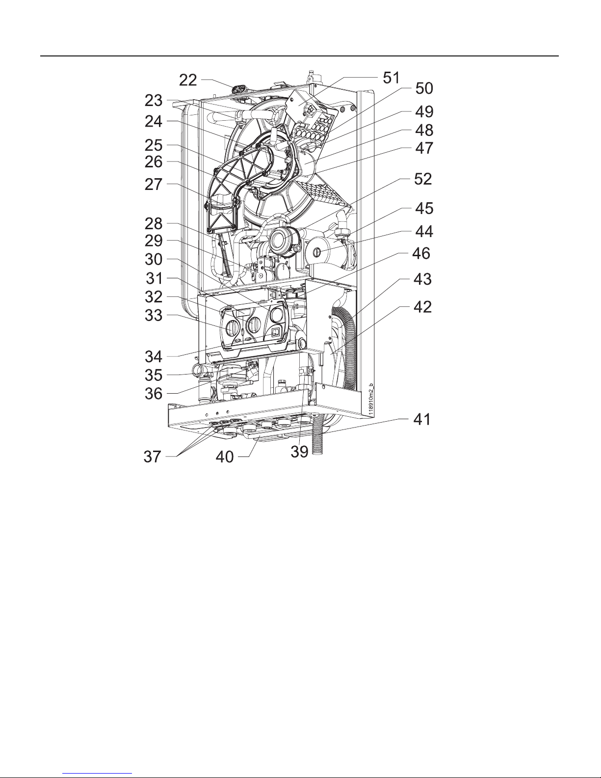
3 - MAIN COMPONENTS
22 - Combustion analysis tap
23 - U1 supply temperature sensor
24 - Burner window
25 - Air/gas manifold
26 - U6 high temperature limit sensor
27 - Flue gas back fl ow preventer
28 - Fan
29 - Gas valve
30 - Heating pressure gauge
31 - Display
32 - Domestic hot water temperature control
33 - Heating temperature control
34 - On/off power switch
35 - Three way valve
36 - U3 domestic cold water temp. sensor
37 - Cable clamp
Figure 1 - Main components
38 - ASME Safety relief valve
39 - U8 return temperature sensor
40 - By-pass pipe
41 - Condensation discharge pipe
42 - Secondary heat exchanger for domestic hot water production
(For P/N see Section 15)
43 - Expansion tank connection pipe
44 - Circulator pump screw
45 - Circulator pump
46 - Condensation discharge trap
47 - Flame-proving electrode
48 - Burner
49 - Right ignition electrode
50 - Left ignition electrode
51 - Spark generator
52 - Flue pressure switch
14
Page 15
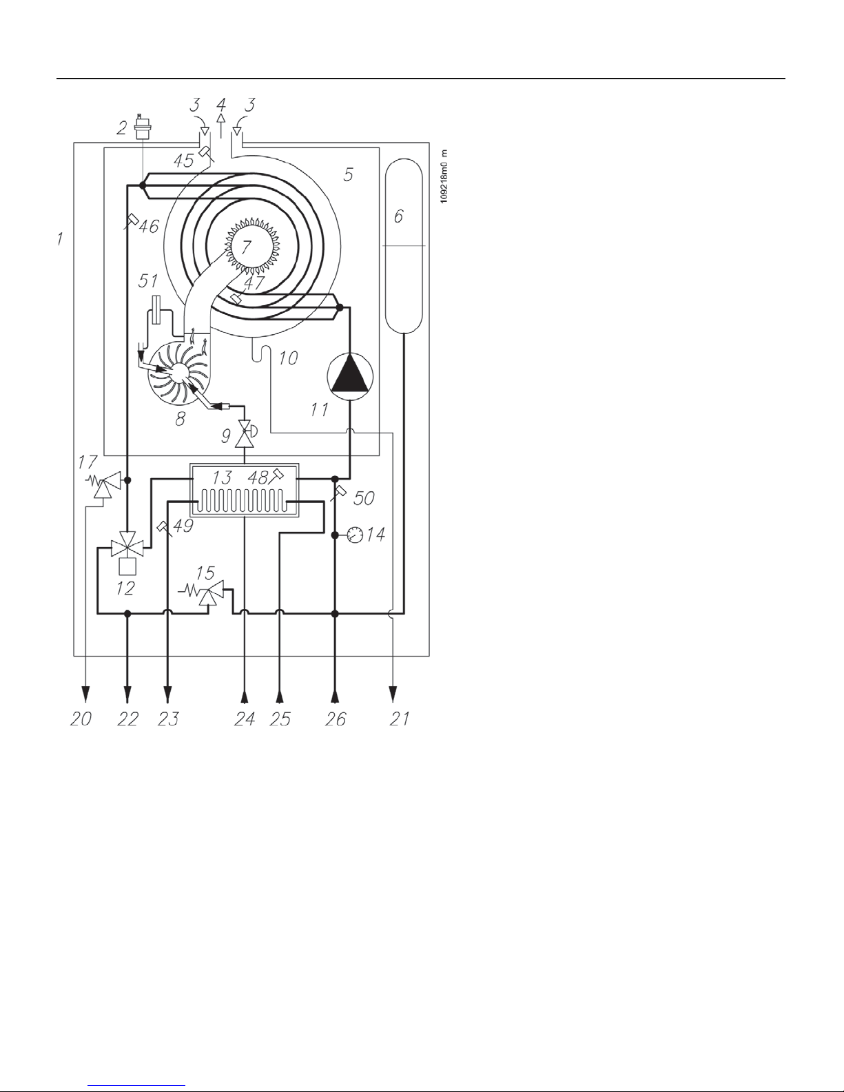
4 - FUNCTION OVERVIEW
Key to fi gure 2:
1 = boiler
2 = automatic air vent
3 = air intake
4 = fl ue gases discharge
5 = sealed combustion chamber
6 = expansion tank
7 = burner
8 = fan
9 = gas valve
10 = condensate discharge trap
11 = circulator pump
12 = 3-way valve
13 = secondary heat exchanger for d.h.w.
14 = pressure gauge
15 = by-pass valve
17 = safety relief valve
21 = condensate discharge pipe
22 = heating supply pipe
23 = domestic hot water outlet
24 = gas inlet
25 = cold water inlet
26 = heating return pipe
45 = U7 = fl ue gas temperature sensor
46 = U1 = boiler temperature sensor
47 = U6 = high limit temperature sensor
48 = U3 = domestic cold water sensor/storage tank
sensor
49 = U2 = domestic hot water temperature sensor
50 = U8 = return temperature sensor
51 = fl ue pressure switch
Figure 2 - PC160™ Hydronic functional schematic
15
Page 16

4 - FUNCTION OVERVIEW
4.1 - Intended use
and functions of
the boiler
This gas-fi red condensing boiler,
is designed to be used for central
heating and producing domestic hot
water.
The maximum output heat is always
guaranteed for the production of
domestic hot water since it is given
priority over space heating demands.
Follow the specifi c procedure in
section 12.7 for the adjustment of the
domestic hot water temperature.
Using a PC160™ boiler you can
create a system for the production
of instantaneous domestic hot water
and a heating system with heating
elements functioning at temperatures
ranging between 68°F (20°C) and
189°F (87°C).
The boiler can also function directly
with a radiant fl oor panel, see section
5.10.
When connecting the boiler to the
heating system the installer must
consider the head loss of the heating
system to verify that the boiler pump
is adequate. Pump curve is shown in
fi gure 4. The same verifi cation must
be done for the domestic installation,
see fi gure 5.
The PC160
to an indirect storage tank for the
production of domestic hot water,
section 7.1.
The PC160
to a room thermostat, section 6.3 and
6.4.
An outdoor air temperature sensor
can also be connected to the boiler for
an outdoor reset supply temperature
control for maximum fuel effi ciency
and comfort (see section 6.5). In this
confi guration the room thermostat will
compensate by adjusting the room
temperature. The room temperature
compensation can be of an ON /
OFF type or two-stage. For further
information on the outdoor-air reset,
refer to section 12.10.
™
can be connected
™
boiler can be connected
The boiler must be connected to
a heating system and a domestic
hot water supply with compatible
specifi cations, performance and
power rating.
Before installation, thoroughly
fl ush the heating and plumbing
systems of any residue
or impurities which might
compromise the smooth running
of the boiler.
This boiler is designed for indoor
installation.
Refer to fi gure 6 for minimum
clearance distances for installation
and future maintenance.
Refer to section 5.2 for minimum
clearance distances from
combustible material.
4.2 - Setting of the
boiler
Section 16 details the setting changes
that should be made to best match the
boiler’s operation to the needs of each
application.
16
Page 17
4 - FUNCTION OVERVIEW
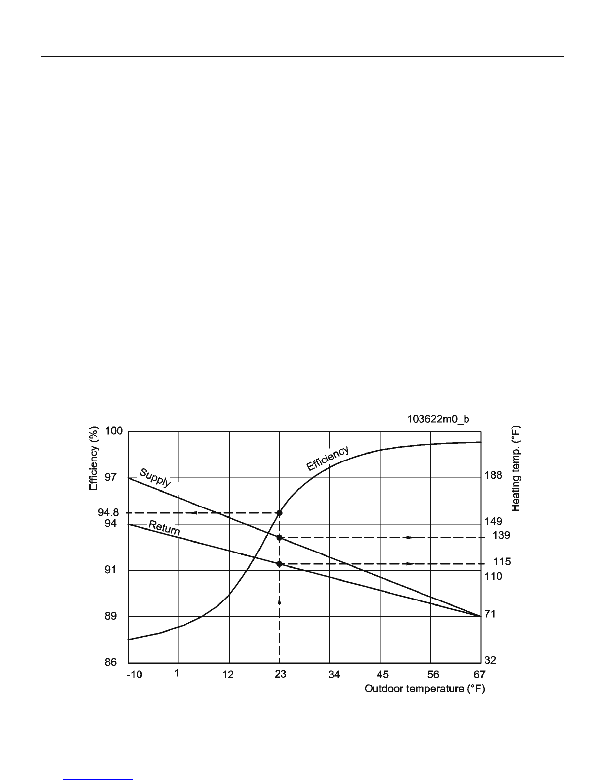
4.3 - Effi ciency up
to 98%
When the outdoor reset is activated
(see section 12.10) and an outside
sensor is connected, this boiler
is designed to always work at
the maximum effi ciency. It will
automatically change the supply
temperature in relation with the
outdoor temperature (Outdoor reset).
The graph in fi gure 3 shows an
example on how it can work.
This graph is an example where is
represented an installation where
the supply and return temperatures
are 139°F and 115°F respectively ,
and the outside temperature is 23°F.
The outdoor reset drives the boiler,
to progressively reduce the supply
temperature and thereby optimize
the effi ciency. It changes from 87%
when outside is -10°F, to 94.8% when
outside is 23°F and up to 98% when
the outside temperature rises up to
67°F.
Figure 3 - Outdoor reset control to optimize the effi ciency
17
Page 18
4 - FUNCTION OVERVIEW
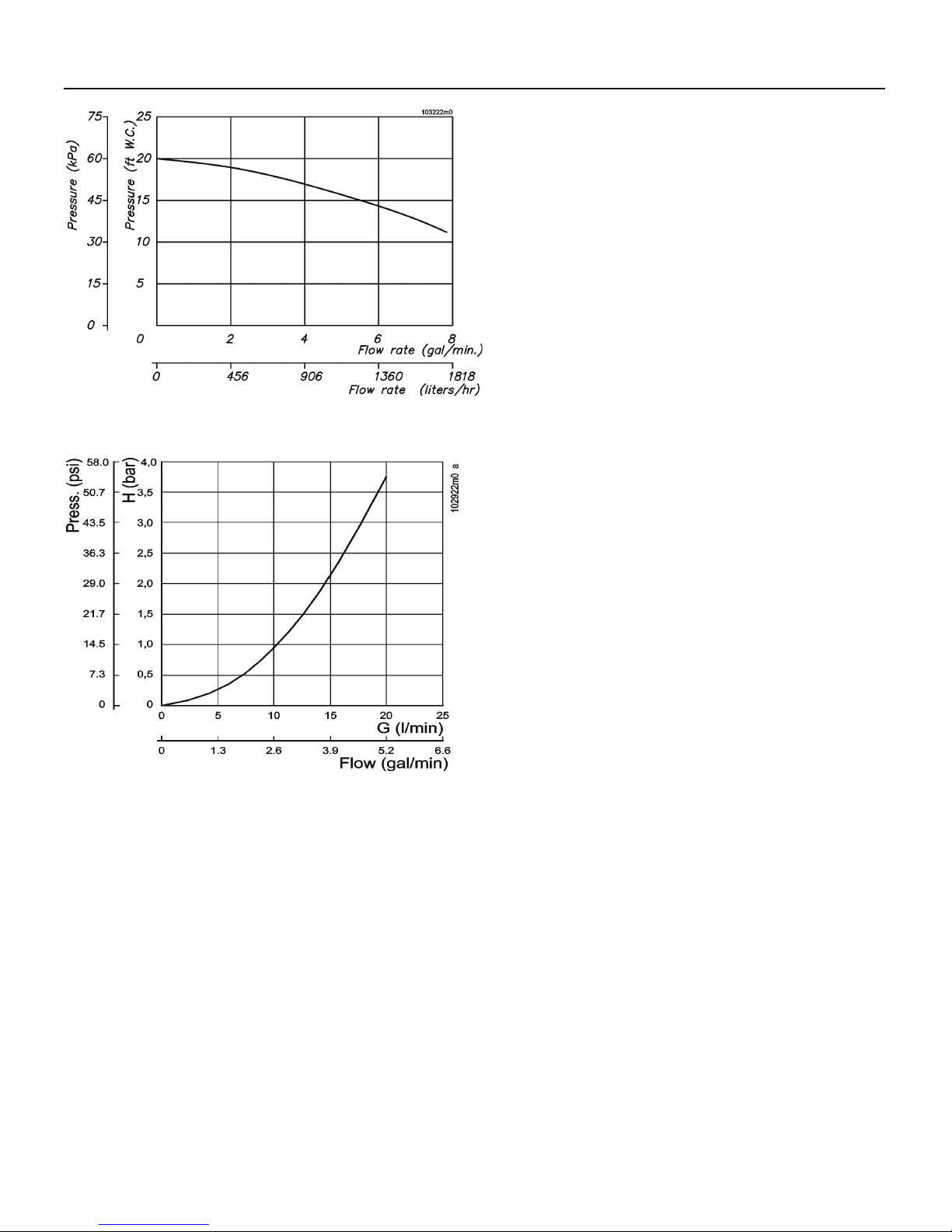
Figure 4 - Available Head for heating circuit
4.4 - Characteristic
curves of heating
system’s residual
head
The PC160™ boiler is fi tted with a
Grundfos circulator pump. The head
available to supply fl ow through
the heating system at the boiler
connections is shown in graph form in
fi gure 4.
4.5 - Characteristic
curve of the
Figure 5 - Domestic Water Coil Head Loss
domestic side
The PC160™ boiler, offers resistance
to the passage of domestic water (see
graph fl ow/pressure of fi gure 5). The
installer or the engineer must take
account of this in order to ensure the
correct domestic water fl ow to the
utilities.
18
Page 19
5 - INSTALLATION - Mounting & gas and water connections
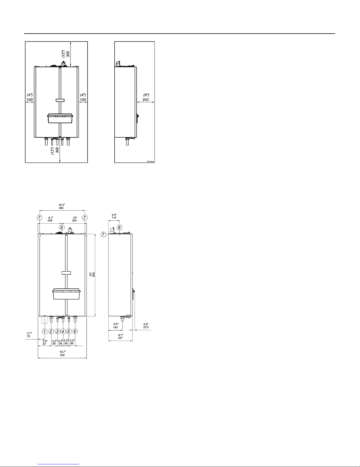
5.1 - Clearances for
installation and servicing
Figure 6 shows the clearances required for installation
and servicing.
NOTE: Service clearances are not mandatory, but
are recommended to ensure ease of service should
it be required.
5.2 - Clearances from
combustible material
This boiler may be installed directly onto a wall of combustible
material with the following clearance:
Ceiling: 2 inches (51 mm)
Front: 2 inches (51 mm)
Rear: 0 inches (0 mm)
Sides: 2 inches (51 mm)
Floor: 2 inches (51 mm)
Figure 6 - Recommended minimum clearance
distances for proper installation and servicing
Concentric vent: 0 inches (0 mm)
Split vent (fi rst 12” from the boiler): 1 inch (25 mm)
Split vent (after 12” from the boiler): 0 inches (0 mm)
1 = Area for power supply cable
2 = Heating supply connection (3/4”)
3 = Domestic hot water connection (3/4”)
4 = Gas connection (3/4”)
5 = Domestic cold water connection (3/4”)
6 = heating return connection (3/4”)
7 = positions for boiler support
8 = Flue discharge/air intake connection
Figure 7 - Dimensions for the PC160
™
19
Page 20
5 - INSTALLATION - Mounting & gas and water connections
5.3 - Choosing the
installation location
WARNING!!! Do not store any fl ammable
materials or liquids in the immediate vicinity of the
boiler. A fi re or explosion can result, causing severe
personal injury , death or substantial property damage.
WARNING!!! LIQUEFIED PETROLEUM (L.P.)
PROP ANE GAS-FIRED BOILER LOCATION REQUIRES
SPECIAL ATTENTION: 1994 UNIFORM MECHANICAL
CODE section 304.6: “LGP Appliances. Liquefi ed
petroleum gas-burning appliances shall not be
installed in a pit, basement or similar location where
heavier than air gas might collect. Appliances so
fueled shall not be installed in above-grade under-fl oor
space or basement unless such location is provided
with an approved means for removal of unburned
gas.” Failure to comply with this provision could
result in severe personal injury or substantial property
damage.
CAUTION!!! The boiler must be installed on a
vertical wall constructed to bear its weight or the boiler
and building may be damaged.
NOTE: The boiler must never be installed on carpeting.
CAUTION!!! This boiler is not designed for direct
outdoor installation. If installed outside of the structure
that it supplies hot water too, it must be sheltered so it is
protected from rain, wind, sun and frost. NEVER place this
boiler in a location that would subject it to temperatures at
or near freezing. Failure to properly locate this boiler can
result in premature failure voiding the warranty .
When locating the boiler the following factors must be
considered:
• the location of vent/air intake terminals;
• connection to the gas supply;
• connection to the water supply;
• connection to the heating system;
• connection to the domestic hot water system;
• connection to the electrical supply;
• disposal of the condensation produced by the boiler;
• connection to the room thermostat;
• piping of the safety relief valve discharge;
• possible connection of the outdoor temperature sensor;
• possible connection of an indirect storage tank, see
section 7.1.
20
Page 21
5 - INSTALLATION - Mounting & gas and water connections
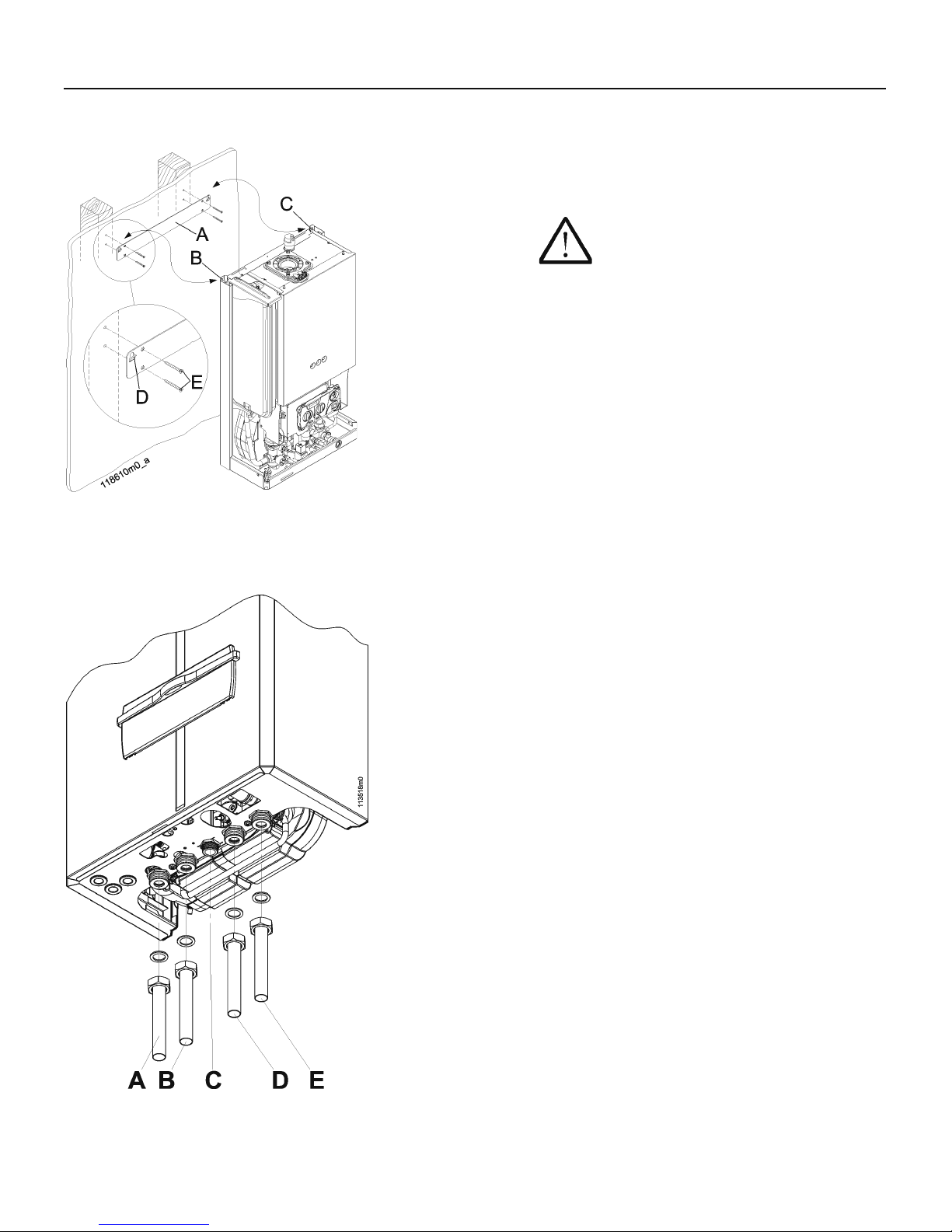
5.4 - Mounting the boiler
Refer to fi gure 8:
1. place the cardboard template, provided with the
boiler, against the wall;
2. ensure that the template is plumb and the
screw holes line up with the wall studs;
CAUTION!!! The wall bracket screws
must be screwed into the buildings framing
or other material capable of supporting the
weight of the boiler or the boiler and building
may be damaged.
3. mark the screw holes for the wall bracket, “A”;
4. remove the cardboard template;
5. install the wall bracket “A”, using the screws
“E”, provided;
6. hang the boiler on the wall bracket, “A”, by
hanging connections “B” and “C” on tabs “D”.
Figure 8 - Wall bracket installation
5.5 - Gas and water
connections
The boiler comes with the fi ttings shown in fi gure 9.
A = heating system supply (3/4”)
B = domestic hot water supply (3/4”)
C = Inlet gas connection (3/4”)
D = domestic cold water (3/4”)
E = heating system return (3/4”)
Figure 9 - Fittings supplied with the boiler
21
Page 22
5 - INSTALLATION - Mounting & gas and water connections
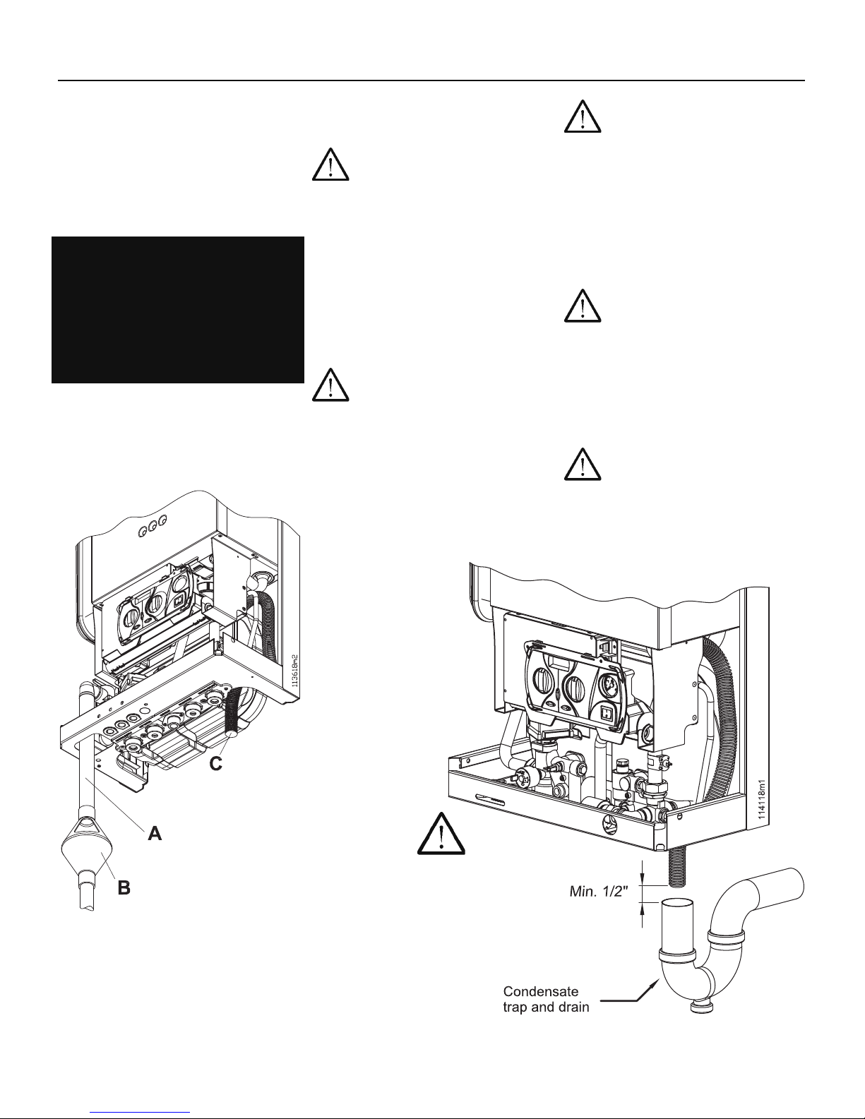
5.6 - Condensate
disposal
WARNING! The condensate trap
must be connected to the boiler
per the following instructions or
combustion gases will enter the
room. This can result in excessive
levels of carbon monoxide which
can cause severe personal injury
or death!
This boiler produces water as a
byproduct of combustion. The boiler
is equipped with a condensate trap,
fi gure 1, item 46, for the evacuation
of condensate and to prevent the
leakage of combustion products.
The condensate trap drains through
pipe “C” shown in Figure 10. The
condensation disposal system must:
be connected to the domestic
waste disposal system by means
of an appropriate trap capable of
preventing the pressurization of the
condensate system and the return
of sewer gases (see fi gure 11);
comply with national and/or local
codes for condensate neutralizer
between pipe “C” of fi gure 10 and
the waste disposal system;
be carried out with a pipe with
an internal diameter equal to or
greater than 1/2 in, 13 mm;
be installed in such a way so as to
avoid the freezing of the liquid;
never discharge into gutters or rain
collectors;
be properly pitched towards the
point of discharge avoiding high
points, which could place the
condensate system under pressure;
CAUTION!!! The condensate
drainage system is designed to
empty all the condensate produced
by one boiler only. Each boiler
must be equipped with its own
condensate drainage system or the
drainage system may malfunction.
5.7 - Near boiler
heating piping
components
1. Boiler system piping: boiler
system piping must be properly
sized. Reducing the pipe size can
restrict the fl ow rate through the
boiler, causing inadvertent high
limit shutdowns and poor system
performance.
2. Boiler system pump: Factory
Installed. Circulators must be
sized to meet the specifi ed fl ow
requirements of 5 GPM.
3. Indirect water heater circulating
pump: Field supplied. The
pump must be sized to meet
the specifi ed minimum fl ow
requirements of 5 GPM. Consult
the indirect water heater operating
guide to determine the fl ow
characteristics of the selected
product used.
4. Boiler isolation valves: Field
supplied. Full port ball valves
are required. Failure to use full
port ball valves could result in
restricted fl ow rate through the
boiler.
5. Domestic indirect hot water
isolation valves: Field supplied.
Full port ball valves are required.
Failure to use full port ball valves
could result in a restricted fl ow
rate through the boiler.
6. Anti scald mixing valves: Field
supplied. An anti scald mixing
valve is recommended (see Figure
16). It is recommended also when
an indirect water heater is present.
7. Unions: Field supplied.
Recommended for unit
serviceability.
8. Pressure relief valve: Factory
supplied. The pressure relief valve
is sized to ASME specifi cations.
9. Indirect Water heaters: Field
supplied. This boiler may be piped
to an indirect water heater to heat
domestic hot water with the space
to heat transfer medium. There
are two options when utilizing an
indirect water heater.
a. The space heating piping will
branch off to fl ow the space
heat transfer medium through a
single wall heat exchanger coil
inside the indirect water heater.
b. The indirect water heater is
connected to the system supply
piping. A pump controlled by
the boilers control will regulate
the fl ow of water through
the indirect water heater.
The indirect water heater’s
temperature will be regulated by
the boiler’s control. The boiler
is pre-confi gured to control the
operation of the DHW pump
with Domestic Hot Water
Prioritization programming.
CAUTION!- It is up to the installer
to ensure the minimum system fl ow
is not less then 5 GPM at any time.
WARNING!!! The National
Standard Plumbing Code, the
National Plumbing Code of Canada
and the Uniform Plumbing Code limit
the pressure of the heat transfer fl uid
to less then the minimum working
pressure of the potable water system
up to 30 psi maximum. Also, the
heat transfer fl uid must be water or
other non-toxic fl uid having a toxicity
of Class 1, as listed in the Clinical
T oxicology of Commercial Products,
5th Edition.
10. Filter: Field supplied. A Filter or
equivalent multipurpose strainer is
recommended at the return pipe
of the boiler to remove system
particles from older hydronic
systems and protect newer
systems.
22
Page 23
5 - INSTALLATION - Mounting & gas and water connections
5.8 - Relief valve
Each boiler is equipped with a safety
relief valve set at 30 psi (2 bar) which
must be piped in accordance with
the ANSI/ASME Boiler and Pressure
Vessel Code, Section IV, to prevent
scalding in the event of a discharge,
see Figures 1, item “38” and fi gure 10.
WARNING!!! Failure to properly
pipe the relief valve discharge can
result in scalding of individuals and
animals. Never install any type of
valve between the boiler and the
relief valve or an explosion causing
extensive property damage, severe
personal injury or death may occur!
5.9 - Supply and
return piping
CAUTION!!! All heating
system piping must be installed in
accordance with the ANSI/ASME
Boiler and Pressure Vessel Code,
Section IV. All applicable local
codes and ordinances must also
be followed. If the boiler is installed
above any radiation elements it
must be fi tted with a low water
cutoff device installed above the
normal boiler water level! Failure
to do this can result in damage the
unit and void the warranty!
CAUTION!!! This boiler
must have adequate water fl owing
through it whenever the burner is
on. Failure to do this will damage
the unit and void the warranty!
CAUTION!!! Before
connecting the boiler to the heating
system the heating system must
be thoroughly fl ushed to remove
sediment, fl ux, fi lings and other
foreign matter. An approved
inhibitor should be added to the
heating system water to prevent
limestone and magnetite deposits
from forming and to protect the
boiler from galvanic corrosion.
CAUTION!!! This boiler is
equipped with an ASME safety
relief valve set at 30 psi (2 bar). The
heating system must be designed
so that no piping or radiation
elements are higher than 65 ft (20
m) or else the hydraulic head of the
system will cause the relief valve to
open.
CAUTION!!! The
manufacturer cannot be held
responsible for any damage caused
by incorrect use of additives in the
heating system.
A = 3/4” pipe extension (not provided)
B = Discharge device open to the atmosphere
(not provided)
C = Condensate discharge pipe
Figure 10 - Relief valve connection
CAUTION!!!
Minimum air gap
of ½” between
discharge pipe and
drain. Failure to do
this will damage
the unit and void
warranty .
Figure 11 - Condensate trap and drain
23
Page 24
5 - INSTALLATION - Mounting & gas and water connections
5.12 - Domestic hot
CAUTION!!! This boiler
can supply heating water at a
temperature up to 190°F (88°C).
If the heating system is built with
materials not able to resist to this
temperature, you must to install a
device that shut-off the boiler before
the material’s limit temperature.
Figure 9 illustrates the position of
the supply and return pipes.
Install a metallic mesh fi lter on the
return pipe to prevent any residue
from the system returning to the
boiler.
Do not use the appliance for
adding any type of additive to the
system.
5.9.1 - Converting a
combi boiler into a
heating only boiler
If you are in possession of a PC160™
boiler you can use it as a heating
system only without using the
domestic hot water circuit. To do so,
simply plug the two fi ttings, items
“3” and “5” of fi gure 7, and move
switch No. 5 (see fi gure 21) from OFF
position to ON position. Now knob
“32” of fi gure 1 is disabled.
5.10 - Low
temperature
heating systems
CAUTION!!! When the boiler
is installed in a low temperature
system, the switch No. 6 in fi gure
21 must be placed in the ON
position to prevent the supply
water temperature from exceeding
113°F (45°C) or damage to the low
temperature system components
could occur (see section 5.9).
With switch No. 6 in fi gure 21, in the
ON position, the boiler will maintain
the supply water temperature between
68°F (20°C) and 113°F (45°C). No
setting changes made from the control
panel will cause the supply water
temperature to exceed 113°F (45°C).
CAUTION!!! To protect the
fl oor panel against over heating
you must to install a safety device
that shut-off the boiler before
it reach the fl oor panel’s limit
temperature.
CAUTION!!! If the boiler
is installed in a radiant panel
heating system using plastic
piping, precautions must be taken
against corrosion caused by water
oxygenation. If the piping does
not incorporate an oxygen barrier,
the radiant panel circuit must be
isolated from the boiler using a
titanium plate heat exchanger.
5.11 - Use of
glycol and other
chemicals
WARNING!!! Never use nonapproved additives or toxic boiler
treatment chemicals in the heating
system as they can cause serious
health problems or possibly death.
Any additives introduced into the
heating system must be recognized
as safe by the United States Food
and Drug Administration.
If glycol is used, it must be used in
accordance with the instructions
supplied with the product.
CAUTION!!! Any additives
added to the heating system must
not be added directly inside the
boiler but through the heating
system piping to prevent damage
to the boiler.
and cold water
CAUTION!!! If the water
hardness is greater than 9 gr/gal
(150 mg/l) we recommend installing
a water softener with fi lter.
Figure 9 illustrates the positioning
of the domestic hot and cold water
pipes.
For servicing purposes, install an
isolation valve upstream from the
cold water inlet.
To correctly set the domestic water
fl ow, install an adjustable fl ow
restrictor upstream the cold water
inlet (see fi gure 16 item “12”)
The PC160
used as heating only boilers.
No connection is needed to the
domestic pipes “B” and “D” of
fi gure 9.
™
boiler can also be
5.13 - Gas supply
piping
WARNING!!! Check that the type
and the pressure of the gas
supplied correspond with those
required for the boiler as stated
on the rating plate. Never use a
gas different than that stated on
the boiler rating plate. Failure
to comply with this warning can
result in a fi re or explosion causing
extensive property damage, severe
personal injury or death!
If the gas type and/or the supply
pressure do not match those stated
on the boiler rating plate the boiler
must be converted to the type
of gas and/or supply pressure
available. A conversion kit is
supplied together with the boiler.
24
Page 25
5 - INSTALLATION - Mounting & gas and water connections
The boiler comes from the factory
ready to be piped to the gas supply.
The National Fuel Gas Code, ANSI
Z223.1/NFPA 54 and local codes
for gas piping requirements and
sizing must be followed.
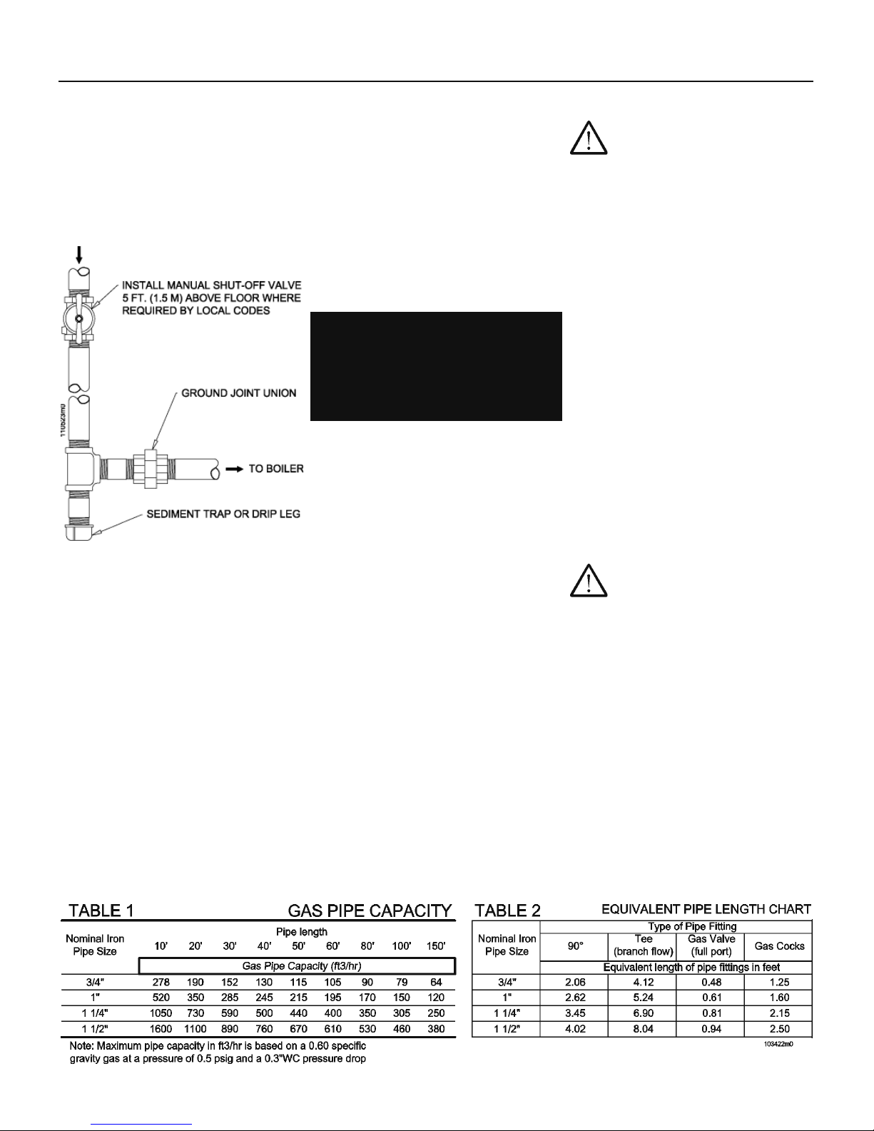
Install a manual gas shutoff valve
and drip leg as shown in Figure 12.
Figure 12 - Gas supply
piping
The gas supply piping to the boiler
must be properly sized to guarantee
that the gas supply meets the
maximum requirements. If more
than one appliance is supplied by
the same gas supply pipe, the gas
supply piping must be sized based
on the maximum possible demand.
Do not neglect the pressure drop due
to pipe fi ttings. Table 1 below, should
be used in conjunction with Table 2
below, to ensure that the gas supply
piping is sized properly. See section
14 for values of “maximum gas supply
pressure” and “minimum gas supply
pressure” and also section 11.7.
Before installation a thorough
internal cleaning of the gas supply
line should be performed. Figure
9 shows the positioning of the gas
connection on the heater.
The boiler and its gas connection
must be leak tested before placing
the boiler in operation.
To avoid damaging the gas control,
perform a leak test at a pressure
of no greater than 20 in W.C. (50
mbar).
WARNING!!! Never use an open
fl ame to test for gas leaks. Always
use an approved leak detection
method. Failure to comply with
this WARNING could result in an
explosion!
The boiler and its individual shutoff
valve must be disconnected from
the gas supply piping during any
pressure testing at test pressures in
excess of 1/2 psi (3.5 kPa).
The boiler must be isolated from
the gas supply piping by closing
its individual manual shutoff valve
during any pressure testing at test
pressures equal to or less than 1/2
psi (3.5 kPa).
Install 100% lockup gas pressure
regulator in supply line if inlet
pressure can exceed 13”W.C. at
any time. Adjust lockup regulator
for 13”W.C. maximum.
Use pipe sealing compound
compatible with propane gas. Apply
sparingly only to male threads of
the pipe joints so that pipe dope
does not block gas fl ow.
5.14- Propane gas
WARNING!!! These boilers
are typically shipped ready to fi re on
natural gas. Check boiler rating plate
to determine which fuel the boiler is
set for. If set to natural gas, it may
be converted to LP by following the
instructions in Section 5.17. Failure
to comply could result in severe
personal injury , death, or substantial
property damage.
Pipe sizing for propane gas
Contact gas supplier to size pipes,
tanks and 100% lockup gas pressure
regulator.
Propane supply pressure
requirements:
1. Adjust propane supply regulator
provided by the gas supplier for
13”W.C. maximum pressure.
2. Pressure required at gas valve
inlet port:
a. Maximum 13”W.C. with no fl ow
(lockup) or with boiler on.
b. Minimum 3”W.C. with gas
fl owing (verify at high fi re).
WARNING!!! Ensure that the
high pressure gas regulator is at least
6-10ft upstream of the appliance.
5.15 - Operating at
high altitudes
For installations in the United States,
the boiler is rated for operation at
altitudes up to 2,000 ft (609 m). For
installations at higher altitudes in
the United States, follow local codes
or, in the absence of local codes,
follow ANSI Z223.1/NFPA No. 54,
The National Fuel Gas Code. For
installations in Canada, the boiler is
rated for installations up to 2,000 ft
(609 m). For installations above this
altitude, follow local/provincial codes.
25
Page 26
5 - INSTALLATION - Mounting & gas and water connections
5.16- Convert the
boiler from Natural
Gas to Propane
Gas or vice versa
WARNING!!! The gas
conversion shall be performed
by a qualifi ed service agency in
accordance with this instructions and
all applicable codes and requirements
of the authority having jurisdiction.
The information in these instructions
must be followed to minimize the
risk of fi re or explosion or to prevent
property damage, personal injury or
death. The qualifi ed service agency is
responsible for the proper conversion
of the boiler. The installation is
not proper and complete until the
operation of the converted appliance
is checked as specifi ed in this
instructions.
WARNING!!! The conversion
shall be carried out in accordance
with the requirements of the
provincial authorities having
jurisdition and in accordance with the
requirements of the CAN-B149.1 and
CAN1-B149.2 installation code.
Contents:
The conversion kit (supplied with the
boiler) is composed of the following
elements, which are necessary for the
gas change:
- a label rating the new gas setting;
- an instruction sheet;
- an orifi ce;
Installing:
in order to make the gas change
please follow the instructions below:
1 - turn off power to the boiler;
2 - open the boiler’s casing (Follow
Section 14.2);
3 - open the instrument panel
(Follow Section 9.2);
4 - Move switch #7 (see Figure 9-2)
from OFF position to ON position;
5 - turn on power to the boiler;
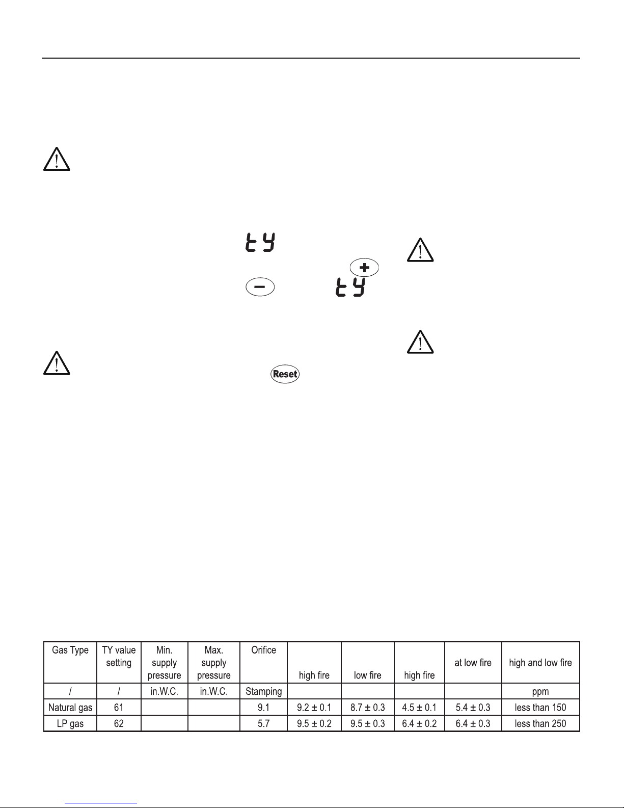
6 - on the boiler’s display you’ll see
followed by a number;
7 - using the push buttons and
set the input to:
- 61 to convert the boiler from LP
GAS to NATURAL GAS
or
- 62 to convert the boiler from
NATURAL GAS to LP GAS,
8 - push button to save the
new value;
9 - turn off power to the boiler;
10 - Move switch #7 (see Figure 9-2)
from ON position to OFF position;
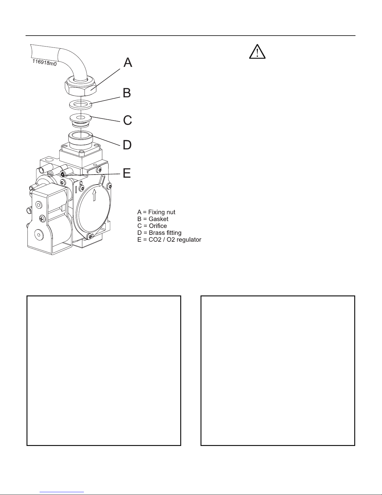
11 - Replace the orifi ce item “C” of
Figure 13 for the correct one
for the type of gas used. Verify
that the stamping on the orifi ce
matches the gas type (See Table
3).
11 - turn on power to the boiler;
12 - Turn completely counter
clockwise the screw E of Figure
13;
13 - Checking gas supply pressure
following Section 12.7. The Gas
supply pressure must be between
the maximum and minimum value
as stated in Table 3.
14 - Verifying the CO2 rate and its
eventual adjustment following
Section 12-9: The boiler during
its normal operation, within a
maximum altitude of 2000 ft, has
a CO2 exhaust rate as shown
in Table 3. If not within range of
value shown, malfunctions will
occur.
WARNING!!! The CO (carbon
monoxide) level should not exceed
values given in T able 3, when
combustion is correct. Failure to
comply with this requirement could
result in severe personal injury , death
or substantial property damage.
WARNING!!! All combustion
measurements must be performed
with calibrated equipment to ensure
proper reading and accuracy . Failure
to comply with this requirement could
result in severe personal injury , death
or substantial property damage.
TABLE 3 SETTINGS OF THE BOILER FOR NATURAL GAS AND LP GAS
313
313
CO2
content at
%%%%
CO2
content at
O2
content at
O2 content CO content at
26
Page 27
5 - INSTALLATION - Mounting & gas and water connections
WARNING!!! If the combustion
levels are not within the range given
in T able 3 for the fi ring rate, shut
the boiler down and contact your
distributor or the boiler manufacturer
(see reference in the last cover
page). Failure to comply with this
requirement could result in severe
personal injury , death or substantial
property damage.
15 - Attach to the front of the boiler
the appropriate conversion label,
found in the conversion kit (see
Figure 14 or Figure 15), stating the
new type of gas adjustment of the
boiler.
a - Apply the label in Figure 15 if the
boiler has been converted to LP
GAS;
b - Apply the label in Figure 14 if
the boiler has been converted to
NATURAL GAS.
Figure 13 - Gas valve
ATTENTION!!!
This heater has been converted for use with
NATURAL GAS
- Maximum inlet gas pressure: 13 In.W.C.
- Minimum inlet gas pressure: 3 In.W.C.
- Manifold pressure: (see rating plate)
- Input rating: (see rating plate)
This water heater was converted on (day-month-year)
___________________to ___________________ gas
with kit nº
by
_________________________________________
___________________________________
___________________________________________
(name and address of organization making this
conversion, who accepts the responsibility for the
correctness of this conversion).
ATTENTION!!!
This heater has been converted for use with
LP GAS
- Maximum inlet gas pressure: 13 In.W.C.
- Minimum inlet gas pressure: 3 In.W.C.
- Manifold pressure: (see rating plate)
- Input rating: (see rating plate)
This water heater was converted on (day-month-year)
___________________to ___________________ gas
with kit nº
by
_________________________________________
___________________________________
___________________________________________
(name and address of organization making this
conversion, who accepts the responsibility for the
correctness of this conversion).
Figure 14 - Label for Natural gas boiler
Figure 15 - Label for LP gas boiler
27
Page 28
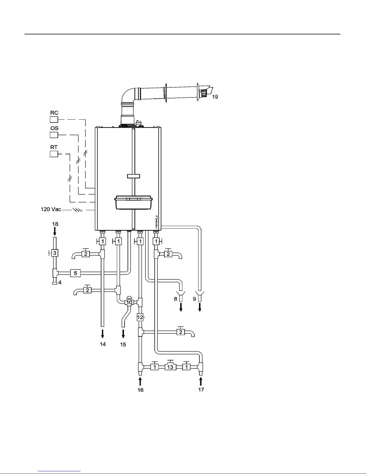
5 - INSTALLATION - Mounting & gas and water connections
5.17 - Suggested
piping and wiring
connections
Figure 16 shows the suggested piping
and wiring connection for the PC160™.
All component listed below, except the
fl ue terminal must be fi eld supplied.
1 = ball valve
2 = drain valve
3 = Manual gas shut-off valve
4 = sediment trap
5 = ground joint union
8 = Relief valve drain
9 = Condensate drain
10 = Domestic mixing valve
12 = Flow restrictor
13 = Fill valve
14 = Heating supply
15 = Domestic Hot Water
16 = Cold water
17 = Heating return
18 = Gas supply
19 = Concentric vent/air intake
terminal
OS = Outdoor sensor (optional)
RC = Remote command (optional)
RT = Room thermostat
120 Vac = Electrical supply
Figure 16 - Typical piping and wiring connections
28
Page 29

6 - INSTALLATION - Electrical connections
6.1 - Electrical
connections: overview
WARNING!!! Label all wires prior to
disconnection when servicing controls. Wiring
errors can cause improper and dangerous
operation!
A TTENTION!!! Au moment de l’entretien des
commandes, étiquetez tous les fi ls avant de les
débrancher. Des erreurs de câblage peuvent
entraîner un fonction-nement inadéquat et
dangereux. S’assurer que l’appareil fonctionne
adéquatement une fois l’entretirn terminé.
WARNING!!! The boiler must be electrically
wired to ground in accordance with the
requirements of the authority having
jurisdiction or, in the absence of such
requirements, with the National Electrical Code,
ANSI/NFP A 70 and/or the Canadian Electrical
Code Part I, CSA C22.1, Electrical Code.
This is an essential safety requirement which
must be checked.
Check that the electrical system is adequate
for the power consumption indicated on the
rating plate.
Line voltage fi eld wiring of any controls or
other devices must conform to the temperature
limitation of type T wire at 95 °F (35 °C), above
room temperature. Use copper conductors
with a minimum size of #14 AWG. Low voltage
wiring must not be less than #18 AWG with a
neoprene, thermoplastic or other equivalent
insulation having a minimum insulation
thickness of 0.012 in, (3 mm).
A properly rated shut-off switch shall be
located at the boiler.
Ensure that the polarity between live and
neutral wires is maintained when connecting
the boiler.
CAUTION!!! Ensure that heating
and water piping is not used as a ground
connections for the electric and telephone
systems. This piping is completely unsuitable
for this purpose and, could rapidly lead to
serious corrosion damage to the boiler,
piping and radiators, voiding the warranty
CAUTION!!! The boiler is not provided
with any protection against lightening strikes.
A = Junction box
B = Plastic spring
C = Opening direction
D = Screws for junction box cover
E = Junction box cover
F = Junction box cover opening direction
G = Electrical supply cable
H = Room thermostat cable (optional)
L = Outside temperature sensor cable (optional)
M = Storage tank temperature sensor
N = Remote command cable (optional)
Figure 17- Junction box
29
Page 30
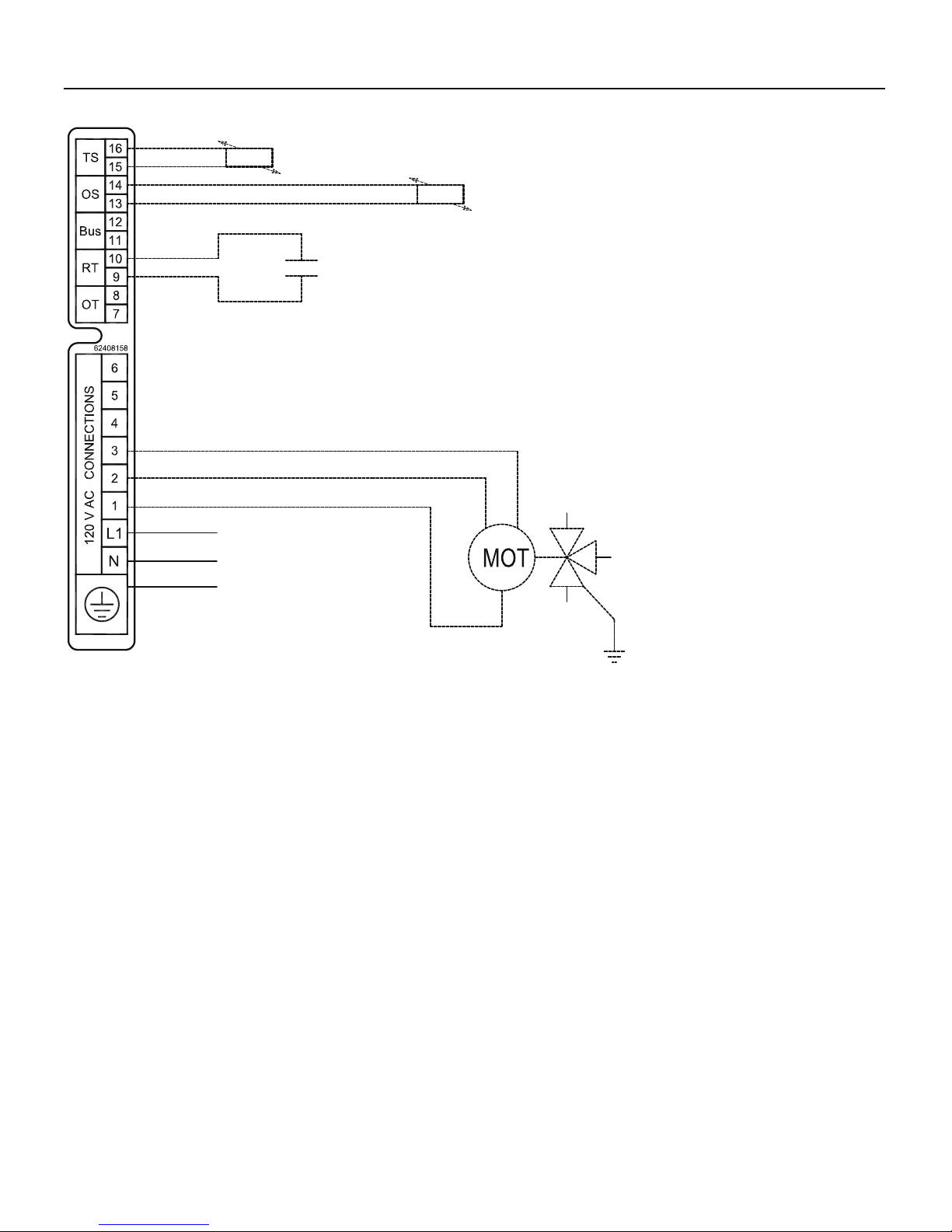
6 - INSTALLATION - Electrical connections
Indirect water heater sensor (optional)
Outdoor sensor (optional)
Room thermostat
120Vac Line domestic hot water
Neutral
120Vac Line central heating
120Vac LINE (HOT)
NEUTRAL
GROUND
Figure 18 - Electrical connections
6.2 - Connecting
the power supply
cable
To connect the electrical power supply
cable, follow the steps below while
referring to fi gures 17 and 18:
remove the boiler casing following
the instructions given in section
13.2;
press the two plastic springs tabs
labeled “B” on the bottom side;
open panel “A” in the “C” direction;
remove the three screws labeled
“D”;
open door “E” in the “F” direction;
install the power supply wires, “G”
as shown;
strip the power supply wires being
careful to leave the ground wire 1in
(25 mm) longer than the other two;
connect the ground wire to the
ground terminal;
connect the 120 volt hot wire to
terminal “L1”;
connect the 120 volt neutral wire to
terminal “N”.
NOTICE! If the 120 volt power wires
are inverted, the boiler will block,
displaying error code E21.
NOTICE! If the boiler is not properly
grounded, the boiler will block,
displaying error code E23
6.3 - Choosing the
room thermostat
This boiler is designed to function with
any type of room thermostat which
has an electrical contact with the
following specifi cations:
- open (end call for heat); closed (call
for heat);
- clean dry contact (not powered);
- electrical capacity of 24Vac, 1A.
External three way
valve for indirect water
heater (Optional)
6.4 - Thermostat
wiring
Install the room thermostat in a part of
the house where the temperature is
as near to average as possible. Avoid
areas subject to sudden temperature
changes such as outside windows or
doors, above radiation elements, near
lamps, etc., (see fi gure 19).
Connect the room thermostat to the
boiler by following the steps below:
remove the boiler casing according
to the instructions given in section
13.2 and open the junction box per
section 6.2;
use a two conductor cable with
a minimum cross section of # 18
AWG between the boiler and the
room thermostat;
route the cable through an empty
cable clamp in the junction box
connect the cable leads to the “RT”
terminals as shown in fi gures 17
and 18.
30
Page 31

6 - INSTALLATION - Electrical connections
NOTICE! the maximum room
thermostat cable length permitted
is 65 ft (20 m). For longer lengths,
up to 300ft (100 m) a shielded
cable, with the shield connected to
the ground, must be used.
WARNING!!! Since the room
thermostat wires conduct 24 Vac,
they must never be run through
conduits containing 120Vac power
wires or an electrical shock hazard
will exist
6.5 - Installing
the outdoor
temperature sensor
(optional)
Install the outdoor temperature
sensor, on an exterior wall of the
building facing NORTH or NORTHEAST, at a height of between 4 ft (1.2
m) and 6 ft (1.8 m) from the ground
level. On multi story buildings, install
the sensor near the upper half of the
second fl oor. Do not install the sensor
above doors, windows or ventilation
outlets nor directly under balconies or
gutter pipes. Do not shield the outdoor
temperature sensor. Do not install the
sensor on walls without overhangs,
or not protected from rain. To connect
the outdoor temperature sensor to the
boiler proceed as follows:
1. remove the boiler casing according
to the instructions given in section
13.2 and open the junction box per
section 6.2;
2. use a two conductor cable with
a minimum cross section of # 18
AWG. between the boiler and the
outdoor temperature sensor.
NOTICE! the maximum outdoor
temperature sensor cable length
permitted is 65 ft (20 m). For longer
lengths, up to 300 ft (100 m) a
shielded cable, with the shield
connected to the ground, must be
used;
WARNING!!! Since the outdoor
temperature sensor wires conduct
24 Vac, they must never be run
through conduits containing 120
Vac power wires or an electrical
shock hazard will exist.
3. connect the outdoor temperature
sensor cable leads to terminals OS
as shown in fi gures 17 and 18;
4. connect the outdoor temperature
sensor cable leads to the ends of
the external temperature sensor.
Set the boiler so that it detects the
outdoor temperature sensor, as
follows:
1. press down the button for
12 seconds until the display starts
blinking and shows ;
2. then press and release the
button several times until the
following parameter appears;
3. using the and keys,
change the parameter value from
00 to 01 or 02 in relation to the
type of outdoor reset desired as
explained in section 12.10;
4. press the button repeatedly
until exiting the menu; the display
will no longer fl ash.
6.6 - Alarm output
Inside the electrical box (see 13.15
and 13.16) there is an electrical
connection for a 120Vac output that is
energized each time the boiler goes
into a lock-out or error condition. The
Installer can use this output to activate
any kind of external signalization
devices such an audible alarm,
phone, or other devices.
Figure 19 - Room thermostat location
31
Page 32

7 - INSTALLATION - Indirect storage tank connections
7.1 - Connecting the
boiler to an indirect
storage tank
This boiler, can be connected to an indirect
storage tank as follows (the water and
electrical connections must be made per
fi gure 20): To make the electrical connections,
follow the steps below while refering also to
fi gure 20:
1. disconnect the boiler from the electrical
supply;
2. remove the boiler casing according to the
instructions given in section 13.2;
3. push the plastic spring tabs “B” shown in
fi gure 21;
4. open the front half of the electrical box in
the “C” direction as shown in fi gure 21;
5. move switch #1, item “D” in fi gure 21, to
its “ON” position as marked on the control
board;
6. ensure that switch #5 is in the OFF position;
7. on the rear side of the electrical junction
box board, if present, disconnect the plug
with two wires (see fi gure 21, item “E”),
corresponding to wires #44 and #45.
8. on the rear side of the electrical box,
disconnect the plug from the diverter
valve (see fi gure 1, item “35”). When you
disconnect the plug you must be sure the
boiler is doing heating. If you are not sure,
light the boiler ON, wait the display show
“F” and then light-off the boiler. Now you
can disconnect the plug from the diverter
valve.
9. use a # 18 AWG two wire cable to connect
the indirect storage tank temperature
1 Outdoor temperature sensor (optional)
2 120Vac electrical supply
3 Heating system supply circuit
4 Room thermostat (fi eld supplied)
5 Heating circuit drain valve (fi eld supplied)
6 Boiler
7 8 Three way valve (fi eld supplied)
9 Gas supply
10 Manual gas shutoff valve (fi eld supplied)
11 12 - Expansion vessel (if the inside one is not suffi cient)
13 Automatic fi ll valve (fi eld supplied )
14 Cold water inlet connection
15 Indirect storage tank (fi eld supplied)
16 Domestic hot water outlet
17 Domestic cold water inlet
Figure 20 - Indirect storage tank connections
sensor to terminals “TS”, item “M”, as per
fi gures 17 and 18;
10. insert the probe of the tank temperature
sensor into the socket of the storage tank.
11. use a #18 AWG four wire cable to connect
the three way valve to terminals “1”, “2”,
“3” and Ground as per fi gures 17 and 18,
where:
“1” = 120Vac Line for heating side
”2” = Neutral
“3” = 120Vac Line for domestic side
WARNING!!! Since the indirect storage
tank temperature sensor wires conduct
24 Vac, they must never be run through
conduits containing 120 Vac power wires
or an electrical shock hazard will exist.
WARNING!!! Once the boiler is connected
to an indirect storage tank, it will perform
a weekly antilegionella cycle. This cycle
raises the storage tank temperature to
140°F one time per week.
32
Page 33

7 - INSTALLATION - Indirect storage tank connections
7.2 - Indirect water
heater priority selection
The boiler is factory set for DHW priority. This
means that the boiler will stay in DHW mode
until the capacity of the indirect water heater
reaches temperature. In some cases this will
result in house cooling because the central
heating function was stopped by the DHW
priority mode. Once the indirect water heater
is satisfi ed the boiler will automatically return
to central heating.
Priority selection is a functionality that toggles
between CH and CHW when they are both
active at the same time. The priority selection
is set with the dP (DHW priority) parameter in
the “installer menu” (see section 12.17)
Each value set into the dP parameter will
correspond to the minutes delay the boiler
toggles between CH and DHW demand.
A = front cover of the electrical box
B = plastic spring to open the electrical box
C = Direction to open the electrical box
D = Switches for the functional setting of the boiler
Figure 21 - Control board and junction box board details
33
Page 34

8 - INSTALLATION - Vent & combustion air
8.1 - Removing
of a boiler from a
common venting
system
WARNING!!! DO NOT connect this
boiler or any other appliance using
a positive pressure, in a common
vent system! Failure to comply with
this WARNING could result in the
accumulation of carbon monoxide
gas which can cause severe
personal injury or death!
When an existing boiler is removed
from a common venting system, the
common venting system is likely to
be too large for proper venting of
the appliances remaining connected
to it. At the time of removal of an
existing boiler, the following steps
shall be followed with each appliance
remaining connected to the common
venting system placed in operation,
while the other appliances remaining
connected to the common venting
system are not in operation.
(a) Seal any unused openings in the
common venting system.
(b) Visually inspect the venting system
for proper size and horizontal pitch
and determine there is no blockage
or restriction, leakage, corrosion
and other defi ciencies which could
cause an unsafe condition.
(c) Insofar as is practical, close all
building doors and windows and
all doors between the space in
which the appliances remaining
connected to the common venting
system are located and other
spaces of the building. Turn on
clothes dryers and any appliance
not connected to the common
venting system. Turn on any
exhaust fans, such as range hoods
and bathroom exhausts, so they
will operate at maximum speed. Do
not operate a summer exhaust fan.
Close fi replace dampers.
(d) Place in operation the appliance
being inspected. Follow the lighting
instructions. Adjust thermostat so
appliance will operate continuously.
(e) Test for spillage at the draft hood
relief opening after 5 minutes of
main burner operation. Use the
fl ame of a match or candle, or
smoke from a cigarette, cigar or
pipe.
(f) Alter it has been determined
that each appliance remaining
connected to the common venting
system properly vents when tested
as outlined above, return doors,
windows, exhaust fans, fi replace
dampers and any other gasburning appliance to their previous
condition of use.
(g) Any improper operation of the
common venting system should
be corrected so the installation
conforms with the National Fuel
Gas Code, ANSI Z223.1 /NFPA 54
and/or CAN/CSA B149.1, Natural
Gas and Propane Instal-lation
Code. When resizing any portion
of the common venting system, the
common venting system should be
resized to approach the minimum
size as determined using the
appropriate tables in Part 11 of
the National Fuel Gas Code, ANSI
Z223.1 /NFPA 54 and/or CAN/CSA
B149. 1, Natural Gas and Propane
Installation Code.
Au moment du retrait d’une chaudière
existante, les mesures suivantes
doivent être prises pour chaque
appareil toujours raccordé au
système d’évacuation commun et
qui fonctionne alors que d’autres
appareils toujours raccordés au
système d’évacuation ne fonctionnent
pas: système d’évacuation
(a) Sceller toutes les ouvertures non
utilisées du système d’évacuation.
(b) Inspecter de façon visuelle le
système d’évacuation pour déterminer la grosser et l’inclinaison
horizontale qui conviennent et
s’assurer que le système est
exempt d’obstruction, d’étranglement de fruite, de corrosion et
autres défaillances qui pourraient
présenter des risques.
(c) Dans la mesure du possible,
fermer toutes les portes et les
fenêtres du bâtiment et toutes
les portes entre l’espace où les
appareils toujours raccordés du
système d’évacuation sont installés
et les autres espaces du bâtiment.
Mettre en marche les sécheuses,
tous les appareils non raccordés
au système d’évacuation commun
et tous les ventilateurs d’extraction
comme les hottes de cuisinère et
les ventilateurs des salles de bain.
S’assurer que ces ventilateurs
fonctionnent à la vitesse maximale.
Ne pas faire fonctionner les
ventilateurs d’été. Fermer les
registres des cheminées.
(d) Mettre l’appareil inspecté en
marche. Suivre les instructions
d’allumage. Régler le thermostat de
façon que l’appareil fonctionne de
façon continue.
(e) Faire fonctionner le brûleur
principal pendant 5 min ensuite,
déterminer si le coupe-tirage
déborde à l’ouverture de décharge.
Utiliser la fl amme d’une allunette ou
d’une chandelle ou la fumée d’une
cigarette, d’un cigare ou d’une pipe.
(f) Une fois qu’il a été déterminé,
selon la métode indiquée ci-dessus,
que chaque appareil raccordé
au système d’évacuation est mis
à l’air libre de façor adéquate.
Remettre les portes et les fenêtres,
les ventilateurs, les registres de
cheminées et les appareils au gaz
à leur position originale.
(g) Tout mauvais fonctionnement
du systéme d’évacution commun
devrait étré corrigé de façon que
l’installation soit conforme au
National Fuel Gas Code, ANSI
Z223.1/NFPA 54 et (ou) aux codes
d’installation CSA-B149. Si la
grosseur d’une section du système
d’ évacuation doit étré modifi ée, le
système devrait étré modifi é pour
respecter les valeurs minimales des
tableaux pertinents de l’appendice
F du National Fuel Gas Code, ANSI
Z223.1/ NFPA 54 et (ou) des codes
d’installation CSA-B149.
34
Page 35

8 - INSTALLATION - Vent & combustion air
8.2 - Venting
systems
WARNING!!! The vent installation
must be in accordance with Part
7, Venting of Equipment, of the
latest edition of the National Fuel
Gas Code, ANSI Z223.1/NFPA 54
or section 7, Venting Systems
and Air Supply for Appliances, of
the CAN/CSA B149.1, Natural Gas
and Propane Installation code or
applicable provisions of the local
building codes. Improper venting
can result in excessive levels of
carbon monoxide which can result
in severe personal injury or death!
Horizontal vent runs must be
sloped upwards not less than 1/4
in/ft (21 mm/m), from the boiler to
the vent terminal.
The vent system shall be installed
so as to prevent the accumulation
of condensate. When horizontal
vent runs exceed 5 ft (1.5m), they
must be supported at 3 ft (0.98 m),
intervals with overhead hangers.
Horizontal vent systems shall
terminate at least 4 ft (1.22 m)
below, 4 ft (1.22 m) horizontally
from any door, window or gravity
air inlet into any building. It must
not terminate less than 4 ft (1.22
m) horizontally from, and in no
case above or below, unless a 4
ft (1.22 m), horizontal distance is
maintained, from electric meters,
gas meters, regulators and relief
equipment and not less than 7 ft
(2.3 m) from any adjacent public
walkway. The bottom of the vent
terminal(s) shall be located at least
5 ft (1.5 m) above the air intake
terminal(s). Avoid terminal locations
likely to be affected by winds,
snowdrifts, people and pets. Item
unique to CANADA: vent system
shall terminate at least 6 ft from
electrical and gas meters.
Due to the high effi ciency of the
boiler it may discharge what looks
like white smoke especially when
the outside air temperature is cold.
This is a simply water vapor, a
purely natural phenomenon and not
a reason for concern.
The minimum clearance
measurement between two vent
end terminations of this kind of
boilers shall be not less than 18”
(1 m).
WARNING!!! The exhaust vent
and the air inlet lines (also in the
coaxial version) must be supported
to prevent sagging. To do this, use
a suitable pipe clamp to support
the lines. Pipe clamps shall support
the line every 3 ft (1 m). Pipe clamp
shall be fi xed in correspondance
of a wall stud. Improper supporting
can result in excessive levels of
carbon monoxide which can result
in severe personal injury or death!
This Boiler requires a special vent
system, designed for pressurized
venting.
You must install air piping from
outside to the boiler air intake. The
resultant installation is Direct Vent
(sealed combustion).
The boiler is to be used for either
Direct Vent installation or for
installation using room combustion
air. When room air is considered see
Section 8.6.
Vent and air must terminate near one
another and may be vented vertically
through the roof or out of a side wall,
unless otherwise specifi ed. Y ou may
use any of the vent/air piping methods
from Figure 22 thru Figure 27. Do
not attempt to install boiler using any
other means.
WARNING!!! DO NOT mix
components from different systems.
The vent system could fail, causing
leakage into the living space. Use
only approved materials listed on 8.1
and 8.2. Improper materials or mixing
materials can result in excessive
levels of carbon monoxide which
can cause several personal injury or
death!
Be sure to locate the boiler such that
the vent and air piping can be routed
through the building and properly
terminated. The vent/air piping lengths,
routing and termination method must
all comply with the methods and limits
given in Section 8.3.
35
Page 36

8 - INSTALLATION - Vent & combustion air
Figure 22 - Side wall two
pipes (Direct venting).
Figure 23 - Vertical two
pipes (Direct venting).
Figure 24 - Side wall air
intake, vertical vent (Direct
venting).
Air
intake
Figure 25 - Vertical
concentric (Direct venting).
Figure 26 - Side wall
concentric (Direct venting).
36
Figure 27 - Side wall one
pipe venting, combustion air
from room (Direct venting).
Page 37

8 - INSTALLATION - Vent & combustion air
8.3 - Design of the
venting system
This boiler can be fi tted with a very
long venting system. However there
is a relationship between the length
of the venting system and the power
input of the boiler. Figure 28 shows
this relation which and installer must
consider when in the designing stage
of the venting.
The maximum length of the Split vent
system is 300 ft (Air intake plus fl ue
exhuast).
The maximum length of the concentric
system is 70 ft.
Each 45° elbow inserted in the
concentric or split venting system, has
a loss of pressure equivalent to 2.5 ft
of linear pipe.
Each 90° elbow inserted in the
concentric or split venting system, has
a loss of pressure equivalent to 5 ft of
linear pipe.
The minimum length of the venting
system (two pipes or concentric) is 1 ft
with one elbow.
8.4 Prevent
Combustion air
contamination
Install air inlet piping as described in
Section 8. You must pipe combustion
air to the boiler air intake. Do not
terminate vent/air in locations that can
allow contamination of combustion air.
WARNING!!! Contaminated
combustion air will damage the boiler,
resulting in possible severe personal
injury , death or substantial property
damage.
Ensure that that combustion air
will not contain any of the following
contaminants.
- Permanent wave solutions
- Chlorinated waxes/cleaners
- Chlorine based swimming pool
chemicals
- Calcium Chloride used for thawing
- Sodium Chloride used for water
softening
- Refrigerant leaks
- Paint or varnish removers
- Hydrochloric acid/muriatic acid
- Cements and glues
- Antistatic fabric softeners used in
clothes dryers.
- Chlorine-type bleaches, detergents
and cleaning solvents found in
household laundry rooms
- Adhesives used to fasten building
products and other similar products.
Do not pipe combustion air near
sources of products that may
contaminate the air combustion, like:
- Dry cleaning/laundry areas and
establishments
- Swimming pools
- Metal fabrication Plants
- Beauty shops
- Refrigeration repair shops
- Photo processing plants
- Auto body shops
- Plastic manufacturing plants
- Furniture refi nishing areas and
establishments
- Remodeling areas
- Garages with workshops
8.5- Install Vent and
Combustion air
piping
WARNING!!! This boiler
must be vented and supplied with
combustion and ventilation air as
described in this section. Ensure
the vent and combustion air supply
comply with these instructions
regarding vent system, air system
and combustion air quality . Inspect
fi nished vent and air piping
thoroughly to ensure all are airtight
and comply with the instructions
provided and with all applicable
codes. Failure to provide a properly
installed vent and air system will
cause severe personal injury or
death.
WARNING!!! Using vent
materials other than those listed
in T able (4) and Table (5), failure to
properly seal all seams and joints,
mixing of venting materials a or
failure to follow vent pipe and fi ttings
manufacturers instructions can result
in personal injury , death or property
damage.
WARNING!!! Never use cellular
(foam) core pipe in vent pipe lines
and fi ttings. Failure to comply can
result in personal injury , death or
property damage.
Figure 28 - Relation between Power input and Vent
system length
WARNING!!! Increasing or
decreasing combustion air or vent
piping is not authorized. Failure to
comply can result in personal injury ,
death or property damage.
NOTICE Installation must comply
with local requirements and with the
National Fuel Gas Code, ANSI Z223.1
for US installations or CSA B149.1 for
Canadian installations.
For installation in Canada, vent
pipe system must be certifi ed to
ULC-S636.
37
Page 38

8 - INSTALLATION - Vent & combustion air
TABLE 4
Vent pipe materials and fi ttings must comply with the following standards
Item Material
Vent pipe and
fi ttings
Pipe cement/primer
Standard for
installation in USA
PVC Schedule 40, 80 ANSI/ASTM D1785
CPVC schedule 40/80 ANSI/ASTM F441
Polypropylene ULC-S636
Stainless steel AL29-4C UL1738
PVC ANSI/ASTM D2564
CPVC ANSI/ASTM F493
Standard for
installation in Canada
ULC-S636
WARNING!!! USE OF CELLULAR CORE PVC, CPVC AND RADEL FOR VENTING SYSTEM IS NOT ALLOWED.
TABLE 5 APPROVED VENT MANUFACTURERS AND ITEMS
Approved vent manufacturers and items
Item Materials Manufacturer/supplier Manufacturer/supplier part number
Concentric roof or wall terminal PVC IPEX (System 636) 196006
Two pipes wall terminal PVC IPEX (System 636) 081219 or 196985
Single pipe wall terminal (90°elbow) PVC IPEX (System 636) 196025
Boiler adapter (80mm to 3” PVC) Polypropylene COSMOGAS 62617303
Bird Screen PVC IPEX (System 636) 196051
Two pipes roof terminal Polypropylene COSMOGAS 62617306 and 61302003
Two pipe wall terminal Polypropylene COSMOGAS 61302004 and 61302003
Single pipe roof terminal Polypropylene COSMOGAS 62617306
Single pipe wall terminal Polypropylene COSMOGAS 61302004
Two or single pipe boiler adapter (80mm to
80mm Polypropylene)
Bird Screen Polypropylene COSMOGAS 61302003
Concentric boiler adapter Polypropylene COSMOGAS 62617224
Concentric roof terminal Polypropylene COSMOGAS 62617304
Concentric wall terminal Polypropylene COSMOGAS 62617232
Single pipe wall or roof terminal Polypropylene Centrotherm (Innofl ue System) IESP0339
Two pipes wall or roof terminal Polypropylene Centrotherm (Innofl ue System) ASEP0339 and ISEL0387UV
Bird screen Polypropylene Centrotherm (Innofl ue System) IASPP03
Single pipe wall or roof terminal Polypropylene Duravent ( PolyPro) 3PPS36B
Two pipes wall or roof terminal Polypropylene Duravent ( PolyPro) 3PPS36B and 3PPS-E90B
Bird Screen Polypropylene Duravent ( PolyPro) 3PPS-BG
Single pipe wall or roof terminal Stainless Steel Duravent (FasNSeal) FSVL3603
Two pipes wall or roof terminal Stainless Steel Duravent (FasNSeal) FSVL3603 and FSELB8803
Boiler adapter (80mm to 3” stainless steel) Stainless Steel Duravent (FasNSeal) FSA-80MM3
Bird Screen Stainless Steel Duravent (FasNSeal) FSBS3
Single pipe wall or roof terminal Stainless Steel Heat Fab ( SGV) SGV03L36
Two pipes wall or roof terminal Stainless Steel Heat Fab ( SGV) SGV03L36 and FSEL8803
Boiler adapter (80mm to 3” stainless Steel) Stainless Steel Heat Fab ( SGV) SGV03AD80
Bird screen Stainless Steel Heat Fab ( SGV) SGV03TM
Polypropylene COSMOGAS 62617286
38
Page 39

8 - INSTALLATION - Vent & combustion air
8.6 - Air inlet pipe
materials
WARNING!!! The air inlet
pipe(s) must be sealed. Improper
sealed can result in excessive levels
of carbon monoxide which can result
in severe personal injury or death!
Choose acceptable combustion air
inlet pipe materials from the following
list:
- PVC, CPVC or ABS Dryer Vent
or Sealed Flexible Duct (not
recommended for rooftop air inlet)
- Galvanized steel vent pipe with joints
and seams sealed as specifi ed in this
section.
- Type “B” double-wall vent with joints
and seams sealed as specifi ed in this
section.
- AL29-4C, stainless steel material
to be sealed to specifi cation of its
manufacturer.
- Polypropylene material to be sealed
to specifi cation of its manufacturer.
NOTICE! PVC, CPVC, ABS Dryer
Vent and stainless steel pipe may
require an adapter (not provided)
to transition between the air inlet
connection on the appliance and the
air inlet pipe
WARNING!!! Using vent or air
intake materials other than those
specifi ed, mixing the specifi ed
materials, failure to properly seal all
seams and joints or failure to follow
the manufacturer’s instructions can
result in personal injury , death or
property damage.
8.6.1 - Sealing of Type
“B” double-wall or
galvanized air inlet pipe
material
Sealing of Type “B” double-wall or
galvanized air inlet pipe material used
for air inlet piping on a sidewall or
vertical rooftop Combustion Air Supply
System:
a. Seal all joints and seams of the air
inlet pipe using either Aluminum
Foil Duct Tape meeting UL
Standard 723 or 181A-P or a high
quality UL Listed silicone sealant.
b. Do not install seams of vent pipe on
the bottom of horizontal runs.
c. Secure all joints with a minimum
of three sheet metal screws or
pop rivets. Apply Aluminum Foil
Duct Tape or silicone sealant to
all screws or rivets installed in the
pipe.
d. Ensure that the air inlet pipes are
properly supported.
WARNING!!! Failure to properly
seal all joints and seams as required
in the air inlet piping may result in
fl ue gas recirculation, spillage of
fl ue products and carbon monoxide
emissions causing severe personal
injury or death.
8.6.2 - Sealing of PVC,
CPVC or ABS air inlet
pipe
The PVC, CPVC, or ABS air inlet pipe
should be cleaned and sealed with the
pipe manufacturer’s recommended
solvents and standard commercial
pipe cement for the material used.
The PVC, CPVC, ABS Dryer Vent or
Flex Duct air inlet pipe should use a
silicone sealant to ensure a proper
seal at the appliance connection and
the air inlet cap connection. Dryer
vent or Flex Duct should use a screw
type clamp to seal the pipe to the
appliance air inlet and the air inlet
cap. Proper sealing of the air inlet
pipe ensures that combustion air will
be free of contaminants and supplied
in proper volume.
When a sidewall or vertical rooftop
combustion air supply system is
disconnected for any reason, the air
inlet pipe must be resealed to ensure
that combustion air will be free of
contaminants and supplied in proper
volume.
WARNING!!! Failure to properly
seal all joints and seams as required
in the air inlet piping may result in
fl ue gas recirculation, spillage of
fl ue products and carbon monoxide
emissions causing severe personal
injury or death.
NOTICE The use of double-wall
vent or insulated material for
the combustion air inlet pipe is
recommended in cold climates to
prevent the condensation of airborne
moisture in the incoming combustion
air.
39
Page 40

8 - INSTALLATION - Vent & combustion air
8.7 - PVC/CPVC
vent piping
materials
WARNING!!! Use only the
materials listed in T ables 4 and 5
for vent pipe, and fi ttings. DO NOT
mix vent systems of different types
or manufacturers, unless listed in
this manual. Failure to comply could
result in severe personal injury , death,
or substantial property damage.
WARNING!!! This appliance
requires a special venting system.
The fi eld provided vent fi ttings
must be connected to the boiler
following Section 8.7.1. Use only the
vent materials, primer, and cement
specifi ed in this manual to make the
vent connections. Failure to follow
this warning could result in fi re,
personal injury , or death.
WARNING!!! Do not insulate
PVC/CPVC exhaust pipe nor install
into an enclosure, closet, alcove
or any other obstruction thereby
preventing the cooling of the exhaust
pipe. Failure to follow this warning
could result in excessive levels of
carbon monoxide or a fi re, which can
result in severe personal injury or
death!
WARNING!!! Improper
installation of PVC or CPVC systems
may result in injury or death.
NOTICE Installation must comply
with local requirements and with the
National Fuel Gas Code, ANSI Z223.1
for U.S. installations or CSA B149.1
for Canadian installations.
NOTICE The installer must use a
specifi c vent starter adapter at the
fl ue collar connection, supplied by the
vent manufacturer to adapt to its vent
system. See Table 5 for approved
vent adapters.
For installation in Canada, vent pipe
system must be certifi ed to ULC-S636
(see Table 4).
NOTICE All vent pipes must be glued,
properly supported, and the exhaust
must be pitched a minimum of a 1/4
inch per foot back to the boiler (to
allow drainage of condensate).
NOTICE Installation of a PVC/CPVC
vent system should adhere to the
PVC/ CPVC vent manufacturer’s
installation instructions supplied with
the vent system.
NOTICE The installer must use a
specifi c vent starter adapter at the
fl ue collar connection, supplied by the
vent manufacturer to adapt to its vent
system. See Table 5 for approved
vent adapters.
8.7.1 - Installing PVC/
CPVC vent and air piping
NOTICE Use only cleaners, primers,
and solvents that are approved
for the materials which are joined
together.
1. Work from the boiler to vent or air
termination. Do not exceed the
lengths given in Section 8.3.
2. Cut pipe to the required lengths
and deburr the inside and outside
of the pipe ends.
3. Bevel outside of each pipe end to
ensure even cement distribution
when joining.
4. Clean all pipe ends and fi ttings
using a clean dry rag (Moisture will
retard curing and dirt or grease will
prevent adhesion).
5. Dry fi t vent or air piping to ensure
proper fi t up before assembling
any joint. The pipe should go a
third to two-thirds into the fi tting
to ensure proper sealing after
cement is applied.
6. Priming and Cementing:
a. Handle fi ttings and pipes
carefully to prevent
contamination of surfaces.
b. Apply a liberal even coat of
primer to the fi tting socket.
c. Apply a liberal even coat
of primer to the pipe end to
approximately 1/2” beyond the
socket depth.
d. Apply a second primer coat to
the fi tting socket.
e. While primer is still wet, apply
an even coat of approved
cement to the pipe equal to the
depth of the fi tting socket.
f. While primer is still wet, apply
an even coat of approved
cement to the fi tting socket.
g. Apply a second coat of cement
to the pipe.
h. While the cement is still wet,
insert the pipe into the fi tting, if
possible twist the pipe a 1/4 turn
as you insert it. NOTE: If voids
are present, suffi cient cement
was not applied and joint could
be defective.
i. Wipe excess cement from the
joint removing ring or beads as
it will needlessly soften the pipe.
8.7.2 - PVC/CPVC air
intake/vent connections
Combustion Air Intake
connection (see Figure 29 Item
“C”). This connection is used to
provide combustion air directly to the
boiler from outdoors. Combustion
air piping must be supported per
guidelines listed in the National
Mechanical Code, Section 305, Table
305.4 or as local codes dictate. To
connect a PVC/CPVC pipe to the air
intake connection proceed as follow
while referring to Figure 29:
1. install boiler adapter “A” above
boiler. Rotate boiler adapter “A” so
as air intake and vent connections
are in the desired left or right
side. Check stamped arrow to
understand which is the vent and
air intake connection.
WARNING!!! Check stamped
arrow on boiler adapter for the correct
side of air intake. Failure to follow
this warning could result in excessive
levels of carbon monoxide or a fi re,
which can result in severe personal
injury or death!
2. insert the clamp “D” into convertor
“A” in the “C” side.
3. insert the adapter “E” into
connection “C” of the convertor
“A”;
40
Page 41

8 - INSTALLATION - Vent & combustion air
4. use the precedent clamp “D” to
mechanically secure the adapter
“E” to the adapter “A”. To do this
tighten the half clamp on the
adapter “A” and half clamp on the
adapter “E”. Tight the clamps with
a tork of 1.5 - 2 lbf ft (2-3 Nm).
5. insert the clamp “F” into convertor
“E”.
6. insert the air inlet PVC/CPVC
pipe, for 2” into the adapter “E”;
7. use the precedent clamp “F” to
mechanically secure the pipe to
the adapter “E”. To do this tighten
the half clamp on the pipe and half
clamp to the adapter “E”. Tight the
clamps with a tork of 1.5 - 2 lbf ft
(2-3 Nm).
Vent connection (see Figure
29 Item “B”).
This connection is used to provide
a passageway for conveying
combustion gas to the outside. Vent
piping must be supported per the
National Building Code, Section 305,
Table 305.4 or as local codes dictate.
To connect a PVC/CPVC pipe to the
vent connection proceed as follow
while referring to Figure 29:
1. install boiler adapter “A” above
boiler. Rotate boiler adapter “A” so
as air intake and vent connections
are in the desired left or right
side. Check stamped arrow to
understand which is the vent and
air intake connection.
WARNING!!! Check stamped
arrow on boiler adapter for the
correct side of vent. Failure to follow
this warning could result in excessive
levels of carbon monoxide or a fi re,
which can result in severe personal
injury or death!
WARNING!!! Check stamped
arrow on boiler adapter for the correct
side of fl ue exhaust and air intake.
Failure to follow this warning could
result in excessive levels of carbon
monoxide or a fi re, which can result
in severe personal injury or death!
WARNING!!! Do not insulate
PVC/CPVC exhaust pipe nor install
into an enclosure, closet, alcove
or any other obstruction thereby
preventing the cooling of the exhaust
pipe. Failure to follow this warning
could result in excessive levels of
carbon monoxide or a fi re, which can
result in severe personal injury or
death!
2. Insert one side of clamp “D” onto
the air intake of boiler adapter “A”
(side C).
3. Insert adapter “E” into side “C” of
boiler adapter “A”;
4. Use clamp “D” to mechanically
secure adapter “E” to boiler
adapter “A”. To do this, tighten
one side of clamp “D” onto boiler
adapter “A” and the other half of
clamp “D” onto adapter “E”. Tight
the clamps with a tork of 1.5 - 2 lbf
ft (2-3 Nm).
5. Insert clamp “F” into adapter “E”.
6. Insert the PVC/CPVC pipe “G”,
into adapter “E” for at least 2”;
7. Use clamp “F” to mechanically
secure pipe “G” to adapter “E”. To
do this, tighten one side of clamp
“F” onto pipe “G” and the other
side of clamp “F” to the adapter
“E”. Tight the clamps with a tork of
1.5 - 2 lbf ft (2-3 Nm).
Figure 29 - PVC/CPVC Venting connection
41
Page 42

8 - INSTALLATION - Vent & combustion air
8.8 - Flue terminal
location in
compliance with
CAN/CSA B149
Vent Termination Minimum Clearances
A = 12” clearances above grade, veranda, porch, deck or balcony
B = 12” clearances to window or door that may be opened
D = 18” vertical clearance to ventilated soffi t located above the terminal within a horizontal distance of 2 feet (0.6 m)
from the centre line of the terminal
E = 18” clearance to unventilated soffi t
F = 9” clearance to outside corner
G = 6” clearance to inside corner
H = 4 ft (USA) not to be installed above a gas meter/regulator assembly within H horizontally from the centre line of
the regulator
H = 3 ft (CANADA) not to be installed above a gas meter/regulator assembly within H horizontally from the centre line
of the regulator
I = 3 ft (USA) clearance to service regulator vent outlet
I = 6 ft (CANADA) clearance to service regulator vent outlet
J = 9” (USA) clearance to non-mechanical air supply inlet to building or the combustion air inlet to any other
appliance
J = 12” (CANADA) clearance to non-mechanical air supply inlet to building or the combustion air inlet to any other
appliance
K = 3 ft (USA) clearance to a mechanical air supply inlet
K = 6 ft (CANADA) clearance to a mechanical air supply inlet
L = 7 ft clearance above paved side-walk or a paved driveway located on public property (a vent shall not terminate
directly above a side-walk or paved driveway which is located between two single family dwellings and serves
both dwellings unless terminated 7ft above sidewalk)
M = 18” clearance under veranda, porch, deck or balcony (only permitted if veranda, porch, deck or balcony is fully
open on a minimum of 2 sides beneath the fl oor
42
Page 43

8 - INSTALLATION - Vent & combustion air
8.9 - Single pipe
vent (not sealed
combustion)
WARNING!!! When utilizing
the single pipe method, provisions
for combustion and ventilation air
must be in accordance with Air for
Combustion and Ventilation, of the
latest edition of the National Fuel
Gas Code, ANSI Z223.1, in Canada,
the latest edition of CGA Standard
B149 Installation Code for Gas
Burning Appliances and Equipment,
or applicable provisions of the local
building codes.
Commercial applications utilizing this
boiler may be installed with a single
pipe carrying the fl ue products to
the outside while using combustion
air from the equipment room. In this
case the following conditions and
considerations must be followed.
WARNING!!! The equipment
room MUST be provided with
properly sized openings to assure
adequate combustion air from
outside. Failure to comply could
result in severe personal injury , death,
or substantial property damage.
• There will be a noticeable increase
in the noise level during normal
operation from the inlet air opening.
• Vent system and terminations must
comply with the venting instructions
set forth in sections 8.1, 8.2, 8.3,
8.4, 8.5, 8.6, 8.7, 8.8.
WARNING!!! Use only the
materials, vent systems, and
terminations listed in T ables 4 and 5.
DO NOT mix vent systems of different
types or manufacturers, unless listed
in this manual. Failure to comply
could result in severe personal
injury , death, or substantial property
damage.
WARNING!!! Fire danger due
to fl ammable materials or liquids. Do
not store fl ammable materials and
liquids in the immediate vicinity of the
boiler.
WARNING!!! Boiler must be
clear and free from combustible
materials, gasoline and other
fl ammable vapors and liquids, and
corrosive liquids and vapors. Never
use chlorine and hydrocarbon
containing chemicals (such as spray
chemicals, solution and cleaning
agents, paints, glues etc.) in the
vicinity of the boiler. Do not store
and use these chemicals in the boiler
room. A void excessive dust formation
and build-up.
WARNING!!! Where exhaust
fans, clothes dryers, and kitchen
ventilation systems interfere with the
operation of appliances, makeup air
shall be provided.
NOTICE Installation must comply
with local requirements and with the
National Fuel Gas Code, ANSI Z223.1
for U.S. installations or CSA B149.1
for Canadian installations.
For installation in Canada, vent pipe
system must be certifi ed to ULC-S636
(see Table 4).
NOTICE All vent pipes connections
must be secured following
manufacturer instruction, properly
supported, and the exhaust must
be pitched a minimum of a 1/4 inch
per foot back to the boiler (to allow
drainage of condensate).
8.9.1 - Combustion Air
and Ventilation openings
WARNING!!! Make sure that
combustion air and ventilation
openings are suffi ciently sized and
no reduction or closure of openings
takes place. Please note these
restrictions and its dangers to the
operator of the boiler and to the
homeowner. Failure to comply could
result in severe personal injury , death,
or substantial property damage.
Outdoor combustion air shall be
provided through opening(s) to the
outdoors. The minimum dimension of
air openings shall not be less than 3
in. (80 mm) diameter.
Two Permanent Openings Method.
Two permanent openings, one
commencing within 12 in. (300 mm)
of the top and one commencing within
12 in. (300 mm) of the bottom, of the
room shall be provided. The openings
shall communicate directly, or by
ducts, with the outdoors or spaces
that freely communicate with the
outdoors, as follows:
1. Where directly communicating
with the outdoors or where
communicating to the outdoors
through vertical ducts, each
opening shall have a minimum
free area of 1 in2 each 4000 Btu/
hr (550 mm2/kW) of total input
rating of all appliances located in
the room.
2. Where communicating with the
outdoors through horizontal
ducts, each opening shall have a
minimum free area of 1 in2 each
2000 Btu/hr (1100 mm2/kW) of
total input rating of all appliances
located in the room.
One Permanent Opening Method.
One permanent opening, commencing
within 12 in. (300 mm) of the top of
the room, shall be provided. The
appliances shall have clearances of
at least 1 in. (25 mm) from the sides
and back and 6 in. (150 mm) from the
front of the appliance. The opening
shall directIy communicate with
the outdoors or shall communicate
through a vertical or horizontal duct
to the outdoors or spaces that freely
communicate with the outdoors and
shall have a minimum free area of
1 in2 each 3000 Btu/hr (700 mm2 /
kW) of the total input rating of all
appliances located in the room.
43
Page 44

8 - INSTALLATION - Vent & combustion air
8.9.2 - Determine location
Locate the vent termination using the
following guidelines:
1. The total length of piping for vent
must not exceed the limits given in
the Section 8.3.
2. You must consider the
surroundings when terminating the
vent:
a. Position the vent termination
where vapors will not damage
nearby shrubs, plants or air
conditioning equipment or be
objectionable.
b. The fl ue products will form
a noticeable plume as they
condense in cold air. Avoid
areas where the plume could
obstruct window views.
c. Prevailing winds could cause
freezing of condensate and
water/ ice buildup where fl ue
products impinge on building
surfaces or plants.
d. Avoid possibility of accidental
contact of fl ue products with
people or animals.
e. Do not locate the terminations
where wind eddies could
affect performance or cause
recirculation, such as inside
building corners, near adjacent
buildings or surfaces, window
wells, stairwells, alcoves,
courtyards, or other recessed
areas.
f. Do not terminate above any
door or window. Condensate
can freeze, causing ice
formations.
g. Locate or guard vent to prevent
condensate damage to exterior
fi nishes.
4. The vent piping must terminate
in an elbow pointed outward as
shown in Figure 46 or 49.
WARNING!!! Do not exceed
the maximum lengths of the outside
vent piping shown in Figures 46 or
49. Excessive length exposed to
the outside could cause freezing of
condensate in the vent pipe, resulting
in potential boiler shutdown.
5. Maintain clearances as shown
in Figure 45 (get references to
“Mechanical draft vent terminal”
only). Also maintain the following:
a. Vent must terminate:
• At least 6 feet from adjacent
walls.
• No closer than 12 inches
below roof overhang.
• At least 7 feet above any
public walkway.
• At least 3 feet above any
forced air intake within 10 feet.
• No closer than 4 feet below or
horizontally from any door or
window or any other gravity air
inlet.
b. Do not terminate closer than
4 feet horizontally from any
electric meter, gas meter,
regulator, relief valve, or other
equipment. Never terminate
above or below any of these
within 4 feet horizontally. Item
unique to CANADA: vent
system shall terminate at
least 6 ft from electrical and
gas meters.
6. Locate termination so it is not
likely to be damaged by foreign
objects, such as stones or balls,
or subject to buildup of leaves or
sediment.
CAUTION!!! Increase the grade clearances of the snow line quote
Figure 30 - Vent position of a Direct vent boiler and of a Mechanical draft boiler (not sealed)
44
Page 45

8 - INSTALLATION - Vent & combustion air
8.10 - Sidewall
termination - Two
pipes
8.10.1 - Vent/air
termination
WARNING!!! A gas vent
extending through an exterior wall
shall not terminate adjacent to a wall
or below building extensions such
as eaves, parapets, balconies, or
decks. Failure to comply could result
in severe personal injury , death, or
substantial property damage.
WARNING!!! Do not connect
any other appliance to the vent pipe
or multiple boilers to a common vent
pipe. Failure to comply could result
in severe personal injury , death, or
substantial property damage.
NOTICE Installation must comply
with local requirements and with the
National Fuel Gas Code, ANSI Z223.1
for U.S. installations or CSA B149.1
for Canadian installations.
8.10.2 - Determine
location
Locate the vent/air terminations using
the following guidelines:
1. The total length of piping for vent
or air must not exceed the limits
given in the Section 8.3.
2. You must consider the
surroundings when terminating the
vent and air:
a. Position the vent termination
where vapors will not damage
nearby shrubs, plants or air
conditioning equipment or be
objectionable.
b. The fl ue products will form
a noticeable plume as they
condense in cold air. Avoid
areas where the plume could
obstruct window views.
c. Prevailing winds could cause
freezing of condensate and
water/ice buildup where fl ue
products impinge on building
surfaces or plants.
d. Avoid possibility of accidental
contact of fl ue products with
people or animals.
e. Do not locate the terminations
where wind eddies could
affect performance or cause
recirculation, such as inside
building corners, near adjacent
buildings or surfaces, window
wells, stairwells, alcoves,
courtyards, or other recessed
areas.
f. Do not terminate above any
door or window. Condensate
can freeze, causing ice
formations.
g. Locate or guard vent to prevent
condensate damage to exterior
fi nishes.
45
Page 46

8 - INSTALLATION - Vent & combustion air
Figure 31 - Two pipes sidewall termination of air and vent
3. The air piping must terminate in
a down-turned elbow as shown
in Figures 31 and 32. This
arrangement avoids recirculation
of fl ue products into the
combustion air stream.
4. The vent piping must terminate in
an elbow pointed outward or away
from the air inlet, as shown in
Figures 31 and 32.
WARNING!!! Do not exceed
the maximum lengths of the outside
vent piping shown in Figures 31 and
32. Excessive length exposed to
the outside could cause freezing of
condensate in the vent pipe, resulting
in potential boiler shutdown.
5. Maintain clearances as shown in
Figures 31 and 32. Also maintain
the following:
a. Vent must terminate:
• At least 6 feet from adjacent
walls.
• No closer than 12 inches
below roof overhang.
• At least 7 feet above any
public walkway.
• At least 3 feet above any
forced air intake within 10 feet.
• No closer than 12 inches
below or horizontally from any
door or window or any other
gravity air inlet.
b. Air inlet must terminate at least
12 inches above grade or snow
line; at least 12 inches below
the vent termination;
c. Do not terminate closer than
6 feet horizontally from any
electric meter, gas meter,
regulator, relief valve, or other
equipment. Never terminate
above or below any of these
within 6 feet horizontally.
6. Locate terminations so they
are not likely to be damaged by
foreign objects, such as stones
or balls, or subject to buildup of
leaves or sediment.
Figure 32 - Two pipes sidewall termination of air and vent
(if space permits)
46
Page 47

8 - INSTALLATION - Vent & combustion air
8.10.3 - Prepare wall
penetrations
1. Air pipe penetration:
a. Cut a hole for the air pipe. Size the air
pipe hole as close as desired to the air
pipe outside diameter.
2. Vent pipe penetration:
a. Cut a hole for the vent pipe. For
either combustible or noncombustible
construction, size the vent pipe hole with
at least a 1/2 inch clearance around the
vent pipe outer diameter (4½ inch hole
for 3 inch vent pipe)
b. Insert a galvanized metal thimble in the
vent pipe hole as shown in Figure 33.
3. Use a sidewall termination plate as a
template for correct location of hole
centers.
4. Follow all local codes for isolation of vent
pipe when passing through fl oors or walls.
Figure 33 - Two pipes sidewall termination
assembly
5. Seal exterior openings thoroughly with
exterior caulk.
8.10.4 - Termination and
fi ttings
1. The air termination coupling must be
oriented at least 12 inches above grade or
snow line as shown in Figures 31 and 32.
2. Maintain the required dimensions of the
fi nished termination piping as shown in
Figures 31 and 32.
3. Do not extend exposed vent pipe outside
of the building more than what is shown
in Figures 31 and 32. Condensate could
freeze and block vent pipe.
Figure 34 - Two pipes multiple boilers vent
terminations
8.10.5 - Multiple vent/air
terminations
1. When terminating multiple boilers terminate
each vent/air connection as shown in
Figure 34.
WARNING!!! All vent pipes and air
inlets must terminate at the same height to
avoid possibility of severe personal injury ,
death, or substantial property damage.
2. Place wall penetrations to obtain minimum
clearance of 12 inches between edge of
air inlet and adjacent vent outlet, as shown
in Figure 34 for U.S. installations. For
Canadian installations, provide clearances
required by CSA B149.1 Installation Code.
3. The air inlet is part of a direct vent
connection. It is not classifi ed as a forced
air intake with regard to spacing from
adjacent boiler vents.
47
Page 48

8 - INSTALLATION - Vent & combustion air
8.11 - Sidewall
termination –
Concentric vent
8.11.1 - Description and usage
The termination kit must terminate outside the
structure and must be installed as shown in
Figure 35. The required concentric termination
kit as well as combustion air and vent pipe
materials are listed in Tables 4 and 5.
8.11.2 - Sidewall termination
installation
1. Determine the best location for the
termination kit (see Figure 35).
2. The total length of piping for vent or air
must not exceed the limits given in Section
8.3.
3. You must consider the surroundings when
terminating the vent and air:
a. Position the vent termination where
vapors will not damage nearby shrubs,
plants or air conditioning equipment or
be objectionable.
b. The fl ue products will form a noticeable
plume as they condense in cold air.
Avoid areas where the plume could
obstruct window views.
c. Prevailing winds could cause freezing
of condensate and water/ice buildup
where fl ue products impinge on building
surfaces or plants.
d. Avoid possibility of accidental contact of
fl ue products with people or animals
e. Do not terminate above any door
or window. Condensate can freeze,
causing ice formations.
f. Locate or guard vent to prevent
condensate damage to exterior fi nishes.
4. Cut one (1) hole 5 inch diameter into the
structure to install the termination kit.
5. Install the Concentric vent kit following the
concentric kit manufacturer’s instruction.
Figure 35- Concentric sidewall termination
clearances
NOTICE Ensure termination location
clearance dimensions are as shown in Figure
35.
48
Page 49

8 - INSTALLATION - Vent & combustion air
CAUTION!!! DO NOT use fi eld-
supplied couplings to extend pipes.
Airfl ow restriction will occur and may
cause intermittent operation.
6. Operate the appliance one (1) heat
cycle to ensure combustion air and
vent pipes are properly connected
to the concentric vent termination
connections.
8.11.3 - Multiventing
sidewall terminations
When two or more direct vent
appliances are vented near each
other, each appliance must be
individually vented and vent
terminations may be installed as
shown in Figure 36. It is important that
vent terminations be made as shown
to avoid recirculation of fl ue gas.
WARNING!!! Do not connect
any other appliance to the vent pipe
or multiple boilers to a common vent
pipe. Failure to comply could result
in severe personal injury , death, or
substantial property damage.
Figure 36 - Concentric sidewall multiple boilers
terminations
49
Page 50

8 - INSTALLATION - Vent & combustion air
8.12 - Vertical
termination - Two
pipes
WARNING!!! Follow
instructions below when determining
vent location to avoid possibility
of severe personal injury , death or
substantial property damage.
WARNING!!! Do not connect
any other appliance to the vent pipe
or multiple boilers to a common vent
pipe. Failure to comply could result
in severe personal injury , death, or
substantial property damage.
Installation must comply with local
requirements and with the National
Fuel Gas Code, ANSI Z223.1 for
U.S. installations or CSA B149.1 for
Canadian installations.
8.12.1 - Determine
location
Locate the vent/air terminations using
the following guidelines:
1. The total length of piping for vent
or air must not exceed the limits
given in the Section 8.3.
2. The vent must terminate at least
3 feet above the highest place in
which the vent penetrates the roof
and at least 2 feet above any part
of a building within 10 horizontal
feet.
3. The air piping must terminate
in a down-turned 180° return
pipe no further than 2 feet from
the center of the vent pipe. This
placement avoids recirculation of
fl ue products into the combustion
air stream.
4. The vent piping must terminate at
least 1 foot above the air intake.
The air inlet pipe and vent pipe
can be located in any desired
position on the roof, but must
always be no further than 2 feet
apart and with the vent termination
at least 1 foot above the air intake.
5. Locate terminations so they
are not likely to be damaged by
foreign objects, such as stones
or balls, or subject to buildup of
leaves or sediment.
8.12.2 - Prepare roof
penetrations
1. Air pipe penetration: cut a hole for
the air pipe. Size the air pipe hole
as close as desired to the air pipe
outside diameter.
2. Vent pipe penetration:
a. Cut a hole for the vent pipe.
For either combustible or
noncombustible construction,
size the vent pipe hole with
at least a 1/2 inch clearance
around the vent pipe outer
diameter: 4 inch hole for 3 inch
vent pipe
b. Insert a galvanized metal
thimble in the vent pipe hole.
3. Space the air and vent holes to
provide the minimum spacing
shown in Figure 37 and listed in
section 10.13.1.
4. Follow all local codes for isolation
of vent pipe when passing through
fl oors, ceilings, and roofs.
5. Provide fl ashing and sealing boots
sized for the vent pipe and air
pipe.
8.12.3 - Termination and
fi ttings
1. Prepare the vent termination and
the air termination elbow (Figure
37) by inserting bird screens.
2. The air piping must terminate in
a down-turned 180° return bend
as shown in Figure 37. Locate
the air inlet pipe no further than
2 feet from the center of the vent
pipe. This placement avoids
recirculation of fl ue products into
the combustion air stream.
3. Maintain the required dimensions
of the fi nished termination piping
as shown in Figure 37.
4. Do not extend exposed vent pipe
outside of building more than
shown in Figure 37. Condensate
could freeze and block vent pipe.
Figure 37 - Two pipes vertical terminations of air
and vent
50
Page 51

8 - INSTALLATION - Vent & combustion air
Air intake
snow line. Provide vent and air intake with bird screen.
Vent
Air intake
Vent
Figure 38 - Two pipes Multiple boilers vertical
terminations
vertically from
vent outlet to
any air inlet
from edge of
air intake pipe
to adjacent
vent pipe from
another boiler
8.12.4 - Multiple vent/air
terminations
1. When terminating multiple boilers,
terminate each vent/air connection
as shown in Figures 38 and 39.
WARNING!!! Terminate all
vent pipes at the same height and
all air pipes at the same height to
avoid possibility of severe personal
injury , death, or substantial property
damage.
2. Place roof penetrations to obtain
minimum clearance of 12 inches
between edge of air intake elbow
and adjacent vent pipe of another
boiler for U.S. installations
(see Figure 38). For Canadian
installations, provide clearances
required by CSA B149.1
Installation Code.
3. The air inlet is part of a direct vent
connection. It is not classifi ed as
a forced air intake with regard
to spacing from adjacent boiler
vents.
Vent
snow line. Provide vent and air intake with bird screen.
Air intake
Vent
Air intake
Figure 39 - Alternate vertical terminations with
multiple boilers
vertically from
vent outlet to
any air inlet
51
Page 52

8 - INSTALLATION - Vent & combustion air
8.13 - Vertical
termination –
Concentric vent
8.13.1 - Description and
usage
Both combustion air and vent pipes
must attach to the termination kit. The
termination kit must terminate outside
the structure and must be installed as
shown in Figure 40.
8.13.2 - Determine
location
Locate the vent/air terminations using
the following guidelines:
1. The total length of piping for vent
or air must not exceed the limits
given in Section 8.3.
2. The concentric terminal must
terminate at least 3 feet above the
highest place in which the vent
penetrates the roof and at least 2
feet above any part of a building
within 10 horizontal feet.
3. Locate termination so it is not
likely to be damaged by foreign
objects, such as stones or balls,
or subject to buildup of leaves or
sediment.
8.13.3 - Vertical
termination installation
1. Determine the best location for the
termination kit (see Figure 40).
2. The total length of piping for vent
or air must not exceed the limits
given in Section 8.3.
3. You must consider the
surroundings when terminating the
vent and air:
a. Position the vent termination
where vapors will not damage
nearby shrubs, plants or air
conditioning equipment or be
objectionable.
b. The fl ue products will form
a noticeable plume as they
condense in cold air. Avoid
areas where the plume could
obstruct window views.
c. Prevailing winds could cause
freezing of condensate and
water/ice buildup where fl ue
products impinge on building
surfaces or plants.
d. Avoid possibility of accidental
contact of fl ue products with
people or animals
e. Do not terminate above any
door or window. Condensate
can freeze, causing ice
formations.
f. Locate or guard vent to prevent
condensate damage to exterior
fi nishes.
4. Cut one (1) hole 6 inch diameter
into the structure to install the
termination kit.
5. Install the Concentric vent kit
following the concentric kit
manufacturer’s instruction.
NOTICE Ensure termination location
clearance dimensions are as shown in
Figure 40.
NOTICE Ensure termination height is
above the roof surface or anticipated
snow level (12 inches in U.S.A. or
18 inches in Canada) as shown in
Figures 40.
CAUTION!!! DO NOT use fi eld-
supplied couplings to extend pipes.
Airfl ow restriction will occur and may
cause intermittent operation.
6. Operate the appliance one (1)
heat cycle to ensure combustion
air and vent pipes are properly
connected to the concentric vent
termination connections.
Vent
Combustion
Air
Roof boot /
Combustion
Air
Vent
Combustion
Air
Minimum
clearance above
highest anticipated
snow level.
above roof.
Support
Figure 40 - Concentric vertical termination
Vent
Combustion
air intake
Minimum clearance above snow
52
Page 53

8 - INSTALLATION - Vent & combustion air
8.13.4 - Multiventing
vertical terminations
When two (2) or more direct vent
appliances are vented near each
other, each appliance must be
individually vented (see Figure 41).
vent or breach vent this appliance to
avoid possibility of severe personal
injury , death, or substantial property
damage.
When two or more direct vent
appliances are vented near each
other, two vent terminations may be
installed as shown in Figure 41. It is
important that vent terminations be
made as shown to avoid recirculation
of fl ue gases.
WARNING!!! NEVER common
Figure 41 - Concentric multiple boilers vertical terminations
53
Page 54

8 - INSTALLATION - Vent & combustion air
8.13.5 - Alternate vertical
concentric venting
This appliance may be installed with a concentric
vent arrangement where the vent pipe is routed
through an existing unused venting system; or by
using the existing unused venting system as a
chase for vent and combustion air routing.
Concentric Venting Arrangement
The venting is to be vertical through the roof. The
annular space between the O.D. of the vent pipe
and the I.D. of the existing unused venting system
is utilized for the combustion air source. The
minimum size of the existing vent system required
to achieve enough annular space for combustion
air is 7 inches.
The upper and lower termination as well as any
other unsealed joints in the existing vent system
must be sealed to ensure that all combustion air
is drawn from under the vent cap as shown in
Figures 42 and 43.
Figure 42 - Alternate
concentric vertical venting (Example n°2)
Approved venting materials must be used as
specifi ed in Tables 4 and 5.
Follow all vent / air termination and clearance
requirements per this section to the appropriate
example. Installation must comply with local
requirements and with the National Fuel Gas
Code. The maximum allowable equivalent vent and
air intake lengths for this venting arrangement are
to be determined from Section 8.3.
If an existing unused venting system is converted
for use with this method of concentric venting,
the installer must ensure that the existing
venting system is clean and free from particulate
contamination that will harm this appliance and
cause increased nuisance calls or maintenance.
See Section 8.4 for a list of corrosive contaminants
and sources. Two example scenarios of a
concentric venting arrangement are shown for
illustrative purposes in Figures 42 and 43.
Figure 43 - Alternate
concentric vertical venting (Example n°1)
54
Page 55

8 - INSTALLATION - Vent & combustion air
8.14 - Existing vent
as a chase
Follow all existing termination and
clearance requirements of section
8.12.
The maximum allowable equivalent
vent and air intake lengths for this
venting arrangement are to be
determined from Section 8.3.
Use only approved venting materials
listed in Tables 4 and 5.
Figure 44 - Alternate
concentric vertical venting (Example n°3)
55
Page 56

9 - INSTALLATION - Split venting system
9.1 - Split system
(polypropylene) or
AL29-4C (UL 1738/UL
C 636) system
The boiler is not supplied with the fi ttings
needed for separate vent and combustion
air systems. A special kit must be ordered
to connect the boiler to separate vent and
combustion air systems. Figure 45 shows
fi tting “A” that can freely turn 360 degrees
for optimum installation versatility.
Pipes or elbows connected directly to
the boiler, must be mechanically secure.
Follow these instructions (make reference
to fi gure 46):
1. prepare the two collars “G” with springs
2. insert the collars “L” in hole “M”;
3. insert pipe “N” inside fi tting “A”
4. tight the two collars “O” in a manner to
Figure 45 - Installation of Split fi tting system
“E” and “F”;
mechanically secure pipe “N” to fi tting
“A”, DO NOT FORCE.
Horizontal vent sections must always
be pitched by at least 1/4 in/ft (21
mm/m) towards the boiler. Horizontal
combustion air sections must always
be pitched away from the boiler by at
least 1/4 in/ft (21 mm/m) to prevent
rain from entering the boiler. The vent
and combustion air intake systems can
be extended up to 300 ft. Each 90°
elbow has is equivalent to 5 ft (1,5m),
of straight pipe. Each 45° elbow has is
equivalent to 2.5 ft (0.75 m), of straight
pipe.
Figure 46 - Connecting the pipes to the fi tting
56
Page 57

9 - INSTALLATION - Split venting system
Horizontal vent systems should be
as short and straight as possible.
The vent system must be both gas
tight and watertight. All seams and
joints must be joined and sealed in
accordance with the vent system
manufacturer’s instructions.
WARNING!!! Carefully follow the
installation steps below for the
assembling the split pipe venting
system (elbows and extensions),
as illustrated in fi gure 47. it is
necessary to properly insert the
male side onto the female side
and mechanically secure them by
using the proper clamps. Improper
venting can result in excessive
levels of carbon monoxide or a fi re,
which can result in severe personal
injury or death!
Figure 47 - Connecting extensions and elbows
Mechanically secure each joint with
the supplied clamps as shown in
fi gure 47. Follow this procedure:
1. insert the Male side “B” into the
Female side “A”;
2. use clamp “C” to keep the two
pipes together;
3. use screws “E” to tighten the clamp
onto both pipes; DO NOT force.
CAUTION!!! If vent and
air intake terminals are located
on the same wall or on the same
roof,maintain the distances given
in fi gure 48, between the vent and
air intake, or fl ue gas recirculation
may occur, causing improper boiler
operation!
CAUTION!!! The air intake
terminal must be protected from
wind by a 90° elbow, see fi gure 48.
Figure 48 - Clearances of Split system
57
Page 58

9 - INSTALLATION - Split venting system
9.2 - Split system
components
Some of the most commonly used components
for installing the Split polypropylene vent and
combustion air systems are listed below:
54301 - No. 1 - Split adaptor 80/80 PP
54344 - No. 2 - 3ft PP M/F extension
54387 - 60 ft PP fl exible extension
54388 - Spacer for PP fl exible extension
54345 - No. 3 - 90° PP M/F in line elbow
54346 - 45° PP M/F in line elbow
54347 - No. 4 - Secure clamp for PP
54352 - No. 5 - Split vertical terminal
54389 - No. 6 - Air intake grid
54417 - No. 7 - Flue exhaust grid
extensions
Figure 49 - Interaxes of Split system
54301
Note: the numbers after the codes
correspond to the numbers in fi gure 50
54389
54352
54387
54417
54344
54388
54345
54347 54346
58
Page 59

9 - INSTALLATION - Split venting system
9.3 - Split system
components
Some of the most commonly used
components for installing the Split
stainless steel vent and combustion
air systems are listed below:
Terminal Type
Elbow Termination w/ Screen 9314TERM n/a 2SVSTEX0390
Tee Termination w/ Screen 9330TEE FSTT3 2SVSTTF-3
Mitered Termination w/ Screen 9390 n/a n/a
Screen Termination 9392 FSBS3 2SVSTPF-3
Air Intake Tee SC03TAD3 n/a n/a
Heatfab Saf T Vent Part
Number
Pro Tech FasNSeal
Part Number
Z FLex
Part Number
59
Page 60

9 - INSTALLATION - Split venting system
9.4 - Split system:
installation
examples
Some installation examples can be
seen in fi gure 50:
1. the fi rst example shows the vent
system directly penetrating the roof
with the collection of condensation
inside the boiler itself. The
combustion air system must be
pitched outward 1/4 in/ft (21 mm/m)
to prevent rainwater from entering
the boiler.
WARNING!!! Roof penetrations
must be made according to the
vent manufacturer’s instructions
and prevailing codes. Failure to
comply with this warning can result
in a fi re causing severe personal
injury or death!
2. the second example shows the vent
system run through a vertical wall.
Condensation is collected inside
the boiler itself. The horizontal
section of the vent system must be
pitched 1/4 in/ft (21 mm/m) towards
the boiler. The intake combustion
air system must be pitched outward
1/4 in/ft (21 mm/m) to prevent
rainwater from entering the boiler.
WARNING!!! Under no conditions,
shall this boiler vent gases directly
into a masonry chimney, nor can an
active chimney be used as a chase.
Failure to comply with this warning
can result in chimney or vent
system failure causing excessive
levels of carbon monoxide which
can cause severe personal injury
or death!
Figure 50 - Installation examples of the Split system (see section 9.2 for the reference of
the numbers)
60
Page 61

10 - INSTALLATION - Coaxial venting system
10.1 - Coaxial
system
The boiler is not supplied with the
fi tting needed for connecting a coaxial
vent/combustion air system. A special
kit must be ordered to connect the
boiler with the Coaxial polypropylene
vent. Figure 51 shows how to install
the Coaxial fi tting above the boiler:
WARNING!!! Carefully follow
installation steps below, for the
coaxial pipe assembly (elbows and
extensions), as illustrated in fi gure
52. it is necessary to properly
insert the internal and external
pipe and mechanically secure
B = Connection fl ange
C = Fixing feet
D = Fixing screw
F = Coaxial vertical adaptor
Figure 51 - Installation of the coaxial fi tting
them by using a stainless steel self
tapping screw. Improper venting
can result in excessive levels of
carbon monoxide or a fi re, which
can result in severe personal injury
or death!
In particular:
1. slip-fi t the extension “1” and “2”
2. drill a suitable hole “3” with a drill
3. insert a suitable stainless steel self
(see fi gure 52) together;
“4” (see fi gure 52) in a position
where the two pipes “1” and “2” are
overlapped;
tapping screw “5” and tight it with a
screwdriver “6”
Figure 52 - Secure fi xing extensions and elbows together
61
It is recommended that wall sleeve
be used when installing the coaxial
system through an exterior wall.
This will allow the system to be
easily slipped out for access during
routine maintenance.
Horizontal coaxial systems must
always be pitched by at least 1/4 in/
ft, (21 mm/m) towards the boiler.
The Coaxial system should extend
out of the wall to the dimensions
shown in fi gure 54.
Page 62

10 - INSTALLATION - Coaxial venting system
10.2 - Coaxial system
components
The following coaxial polypropylene vent and
combustion air system components are available, on
request, for installing the Coaxial system
54303 - No. 1 - In line 90° PP coaxial M/F elbow
54303
54304 - No. 6 - In line 45° PP coaxial M/F elbow
54302 - No. 7 - 3ft (1m) PP coaxial extension
54348 - No. 3 - PP coaxial roof end piece
54342 - No. 5 - PP Coaxial wall end piece
54340 - No. 8 - PP straight coaxial adaptor
Note: the numbers after the codes correspond to
the numbers in fi gure 53.
54304
54340
54302
54348
54342
62
Page 63

10 - INSTALLATION - Coaxial venting system
10.3 - Coaxial system
components
Some of the most commonly used components
for installing the coaxial stainless steel vent and
combustion air system are listed below.
Terminal Type
Elbow Termination w/ Screen 9314TERM n/a 2SVSTEX0390
Tee Termination w/ Screen 9390TEE FSTT3 2SVSTTF-3
Mitered Termination w/ Screen 9390 n/a n/a
Screen Termination 9392 FSBS3 2SVSTPF-3
Horizontal Termination Adapter SC03HT n/a n/a
Heatfab Saf T Vent
Part Number
Pro Tech FasNSeal
Part Number
Z FLex
Part Number
63
Page 64

10 - INSTALLATION - Coaxial venting system
10.4 - Coaxial
system: installation
examples
When a coaxial vent and combustion
air system is installed, fi gure 53,
whether vertical or horizontal, it
must be sloped 1/4 in/ft, (21 mm/m)
towards the boiler.
the distances given in fi gure 54,
between the vent terminal and the
wall and also between the vent
terminal and the ground level
(snow line).
Maintain 3ft distance also between
the vent terminals of two or
multiple boilers (see fi gure 54).
CAUTION!!! Maintain
Figure 53 - Installation examples for
the coaxial pipe (see section 10.2 for
the reference of the numbers)
Figure 54 - Clearances for the coaxial
vent terminals of two boilers, in a vertical
wall or in a roof
64
Page 65

11 - OPERATING
11.1 - Operating
Before starting the boiler, the following
must be done.
11.1.1 - User instructions
The user must be correctly instructed
by the installer, on how to operate the
boiler, in particular:
Make sure that the user keeps this
manual and all other documentation
included with the boiler.
Make sure that the user
understands never to tamper
with gas control settings and the
risk of CO poisoning should an
unauthorized individual do so
Make sure that the user is informed
of all the special measures to be
taken for combustion air inlet and
discharging fl ue gases, and that
these must not be modifi ed.
Make sure that the user knows
how to adjust temperatures,
controls and the room thermostats
for maximum effi ciency.
11.1.2 - Filling the
condensate trap
The condensate trap is positioned
inside the boiler as shown in fi gure 1,
item “46”. It must be fi lled with water
to prevent the leakage of fl ue gases
from the condensate drainpipe, item
“41” in fi gure 1. To fi ll the condensate
trap proceed as follows:
1. unscrew “E” screw (Figure 55);
2. remove fl ange “D” and O-Rings “C”
(Figure 55)
3. With a rubber tube and a funnel,
slowly pour approximately 4 oz.
(100 ml), of water into the “B”
opening - DO NOT put water into
the “A” opening (Figure 55);
4. re-install fl ange “D” and O-Rings
“C” and reinstall screw “E” (Figure
55);
WARNING!!! If boiler stays off for
more than 3 months, repeat the
above operation to again fi ll the
condensate trap.
11.1.3 - Filling the heating
system
WARNING!!! Never use nonapproved additives or toxic boiler
treatment chemicals in the heating
system as they can cause serious
health problems or possibly death.
Any additives introduced into the
heating system must be recognized
as safe by the United States Food
and Drug Administration.
CAUTION!!! The heating
system must be fi lled with clean
water from the domestic water
system. Contaminated water can
damage the boiler voiding its
warranty.
CAUTION!!! The addition
of any chemical substances, such
as anti-freeze, must be carried
out according to the product
instructions. Read and follow
instructions in sections 13.10 and
13.11 to prevent problems.
Figure 55 - Filling the
condensate trap
To fi ll the heating system, proceed as
follows:
1. open the automatic air vent, shown
as item “1” in fi gure 1, two turns;
2. open the fi ll valve located under
the boiler and proceed to fi ll the
heating system and boiler until the
pressure gauge, item “30” in fi gure
1, reads 20 psi (1.5 bar) and “FILL”
disappears from the display;
3. check that there is no water leaking
from the fi ttings. If there is the leaks
must be eliminated;
4. close the fi ll valve;
5. check the pressure gauge during
the purging process. If the pressure
has dropped, re-open the fi ll valve
to bring the pressure back up to 20
psi (1.5 bar).
Figure 56 - A = Purge screw
for the domestic hot water
heat exchanger
65
Page 66

11 - OPERATING
11.1.4 - Filling the
domestic hot water heat
exchanger
Once the heating system has been
fi lled and purged, the domestic hot
water heat exchanger must be fi lled
as follows:
1. connect a rubber tube to the
pressure coupling “A” shown in
fi gure 56 and place the end in an
empty bucket or sink;
2. loosen screw “A” as shown in fi gure
56 until air can be heard escaping;
3. once the water runs clear of air
bubbles tighten screw “A”;
4. remove the tube and check that
there are no water leaks.
11.1.5 - Auto-purging the
heating system
Each time the on/off power switch,
item “34” in fi gure 1, is switched
on, an auto-purging cycle lasting 3
minutes begins. The auto-purging
process involves the turning the pump
on and off in order to remove any air
trapped in the heating system. Before
starting the auto-purging cycle the
automatic air vent, item “1” shown in
fi gure 1 must be opened.
11.2 - General
warnings
concerning gas
supply
When starting up the boiler for the fi rst
time the following must be checked:
That the boiler is supplied with the
type of fuel that it is confi gured to
use. Read sections 11.3 and 11.4
That the gas supply pressure is
within the maximum and minimum
values given in listed on the
boiler rating plate. The gas supply
pressure must be checked with
boiler on and the boiler off.
That the gas supply system is
provided with all the safety devices
and controls required under current
national and local codes.
That the vent and combustion
air terminals are free from any
blockages.
That the condensate drain tube is
properly connected.
WARNING!!! If you smell gas:
Do not try to light any appliance.
Do not touch any electrical
switch. Do not use any phone in
your building.
Immediately call your gas
supplier from a neighbor’s
phone. Follow the gas supplier’s
instructions.
If you cannot reach your gas
supplier, call the fi re depart-
ment.
Failure to follow the above steps
can result in a fi re or explosion
causing property damage, personal
injury or loss of life!
11.3 - Confi rming
the boiler’s gas
type
The type of gas and the gas supply
pressure that the boiler is set up for is
listed on the rating label.
The boiler can operate using one of
the following two gases:
NATURAL GAS
Maximum supply pressure = 11
in.W.C. (27.5 mbar).
Minimum supply pressure = 1.5
in.W.C. (3.8 mbar).
LP Gas
Maximum supply pressure = 13
in.W.C. (32.5 mbar).
Minimum supply pressure = 8 in.W.C.
(20 mbar).
11.4 - Gas type
conversion
If the gas available at the installation
site is not the type the boiler is
confi gured to use, the boiler must be
converted. Special conversion kits
are available for this purpose. The
instruction inside the conversion kit
must be followed.
WARNING!!! Conversion of the
boiler to use another type of gas
must be carried out by a qualifi ed
technician. Improper conversion
of the gas valve could result in a
fi re or an explosion causing severe
personal injury or death!
11.5 - Start-up
1. Open the manual gas shut off
valve, fi gure 16, item “3”.
2. Switch the on/off power switch, item
“34” in fi gure 1, to “on”.
3. If the display shows code E 21,
it means that the polarity has not
been observed between the hot
and neutral wires. If this happens
the wires must be switched.
4. Upon start-up, an is shown for
3 minutes while the boiler goes
through its heating system purge
cycle as described in section
11.1.5. To by-pass this stage, press
the and keys together
until a blinking appears.
Then press the button.
5. Rotate knobs “32” and “33”
shown in fi gure 1 to the desired
temperature.
6. The boiler will fi re only when
the room thermostat calls for
heat. If an external temperature
sensor is connected, check that
the temperature calculated is
higher than the minimum running
temperature as explained in section
12.10.
7. If the pump indicator is illuminated,
item “6” in fi gure 64, but the pump
is not running, item “45” in fi gure 1,
it may be stuck. If this is the case it
can be released by removing screw
“44” shown in fi gure 1 and turning
the screw underneath.
8. If the pump indicator is illuminated
but the heating system does not
heat up, repeat the air purging
operations on both the boiler and
the heating system.
66
Page 67

11 - OPERATING
11.6 - Ignition
control testing
After placing the boiler in operation,
the ignition control’s safety shutoff
function must be tested as follow:
1. turn the power switch (item “34” in
fi gure 1) to on;
2. close the room thermostat to create
a call for heat;
3. turn knobs “32” and “33” in fi gure 1
to their maximum position;
4. wait a few minutes for the burner
to light-up as indicated when
light “3” shown in fi gure 64 stays
illuminated.
5. close the manual gas shutoff valve,
see fi gure 16, item “3”;
6. after 40 seconds, the display must
show L01;
7. open the manual gas shutoff valve,
see fi gure 16, item “3”;
8. verify your gas meter, gas fl ow
must be zero.
WARNING!!! If gas fl ow occurs,
close the manual gas shutoff valve
and troubleshoot the system to
determine why there is gas fl ow
when the gas valve should be
deenergized. Do not operate the
boiler until the problem is resolved
or a fi re or explosion causing
property damage, personal injury
or loss of life may occur!
11.7 - Gas supply
pressure checking
5. open the manual gas shut off valve,
fi gure 16, item “3”;
6. check that the gas supply pressure
does not exceed the “maximum
gas supply pressure” as stated in
section 14;
7. turn the power switch to on and
generate a heat demand by turning
knob “33” shown in fi gure 1 to its
maximum setting. Also ensure that
the room thermostat is calling for
heat;
8. press the and keys
at the same time for more than
10 seconds, the display will show
;
9. press the key until the
display shows . Now the
boiler will run for 10 minutes at
maximum input;
10. check the manometer to make
sure the gas supply pressure does
not drop below the “minimum
gas supply pressure” as stated
on section 14. If the gas supply
pressure does not fall within the
above values, adjust the upstream
gas pressure regulator to bring
the gas supply pressure within
the maximum and minimum range
listed on section 14.
After verifying the correct gas
pressures disconnect the manometer,
turn the screw in pressure connection
“D” in fi gure 57, clockwise until snug
and check for any gas leaks.
C - Service pressure port
D - Inlet gas pressure port
E - High fi re, CO2 adjusting screw
F - Low fi re, CO2 adjusting screw
Figure 57 - Gas valve
and adjustment
The gas supply pressure must match
that listed on the boiler rating label.
Check the gas supply pressure by
following the steps below:
1. close the manual gas shut off valve,
fi gure 16, item “3”;
2. follow the steps in section 13.2 to
remove the front cover;
3. turn the screw in pressure port
“D” shown in fi gure 57 three turns
counterclockwise;
4. connect a manometer with
graduations of at least 0.1 in.W.C.
(0.25 mbar) to the inlet gas port “D”
shown in fi gure 57;
67
CAUTION!!! Never force
the pressure connection screw or
the gas valve will be damaged!
WARNING!!! Never use an open
fl ame to check for gas leaks, a
fi re or an explosion could result
causing severe personal injury or
death!
Page 68

11 - OPERATING
Figure 58 - Combustion air pressure probes
11.8 - Check the
combustion air pressure
The boiler has a factory-set air/gas ratio. The pressure
of the gas at the burner is indirectly controlled by the
blower. The combustion air pressure must be checked
as follows while refering to fi gures 58 and 59:
1. use a differential manometer with a precision of at
least 0.1 in.W.C. (0.25 mbar);
2. close the manual gas shut off valve, fi gure 16 item
“3”;
3. open the boiler casing following section 13.2;
4. press the two plastic spring tabs labeled “B” shown
in fi gure 21 and rotate the electrical box;
5. remove plug “B”;
6. turn pressure probe screw “C” one turn
counterclockwise;
7. insert tube “F”, from the negative side of the
manometer, through the opening of plug “B”, and
connect it to pressure probe “C” as shown in fi gure
59;
8. remove plug “A” from the pressure probe and
connect the differential positive side of the
manometer to it;
9. the manometer connections must be made as
shown in fi gure 59, to get the correct pressure
reading;
10. replace panel “H” of fi gure 65 and latch it closed.
If panel “H” is not properly in place the manometer
reading will not be accurate;
11. turn the power switch to on, item “34” in fi gure 1;
Figure 59 - Checking the combustion air pressure
12. press the and keys together for more
than 10 seconds, until a blinking is displayed;
13. the combustion blower will run at maximum speed
for 10 minutes. During this time the burner will not
light;
14. compare the pressure on the manometer with the
table in section 14, “Combustion air pressure”.;
15. if the combustion air pressure is too low, check
that there are no obstructions in the combustion air
and vent systems. Also make sure that panel “H” is
properly sealed;
16. if the combustion air pressure is within tolerance
press the button to return the boiler to its
normal running mode;
17. once the combustion air pressure check has
been performed, disconnect the manometer, close
pressure probe screw “C”, close the boiler casing,
turn the manual gas shut off valve on and proceed
with the check and adjustment of CO2, section 11.9.
68
Page 69

11 - OPERATING
11.9 - Checking
and adjusting CO2
levels
Section 14 lists the correct CO2
ranges for a boiler running at normal
operating conditions at an altitude
below 3000 ft (1000m). CO2 values
outside of the ranges given in section
14 may lead to malfunctioning of the
boiler and cause it to prematurely fail.
To check the CO2 value, carry out a
combustion analysis as follows while
referencing fi gure 60:
1. carefully remove items “E”, “D” and
“C” from the combustion air/ vent
fi tting:
2. generate a call for heat or, if this is
not possible, fully open a hot water
faucet;
3. press the
for more than 10 seconds, the
display will show a blinking ;
4. press the key until the
display shows if a call for
heat has been generated or until
is displayed if a domestic hot
water demand has been generated.
The boiler will now run for 10
minutes at low fi re input.
5. wait 2 to 3 minutes for the CO2 to
stabilize;
6. insert the probe of a calibrated
combustion analyzer into port “B”
and take a fl ue gas sample;
7. compare the CO2 reading with
the low fi re range given in section
14 making sure to use the range
for the gas type in use. If the CO2
reading is outside the specifi ed
range, it must be adjusted.
To adjust the low fi re CO2 proceed as
follows:
1. use a screwdriver to remove the
gas valve cap, item “F” in fi gure 57;
2. turn the regulator screw found
under cap “F” clockwise to increase
the CO2, counter-clockwise to
decrease the CO2;
3. turn the regulator screw in small
increments and wait for the CO2 to
stabilize to prevent overshooting
the desired value:
4. replace the gas valve cap, item “F”
in fi gure 57;
5. seal screw “F” with red paint or nail
polish to discourage tampering.
and keys
7. wait 2 to 3 minutes for the CO2 to
stabilize;
8. insert the probe of a calibrated
combustion analyzer into port “B”
and take a fl ue gas sample;
9. compare the CO2 reading with the
high fi re range given in section
14 making sure to use the range
for the gas type in use. If the CO2
reading is outside the specifi ed
range, it must be adjusted.
To adjust the CO2 proceed as follows:
1. use a screwdriver to turn screw “E”
shown in fi gure 57;
2. turn screw “E” clockwise to reduce
the CO2, counter-clockwise to
increase the CO2;
3. turn screw “E” in small increments
and wait for the CO2 to stabilize to
prevent overshooting the desired
value:
4. seal screw “E” with red paint or nail
polish to discourage tampering.
5. press the button to return
the boiler to its normal operating
mode.
WARNING!!! Compare also CO
(carbon monoxide) reading, with
the value given in section 14. If this
is higher STOP the boiler and call
the service department (see phone
number on the last cover page
NOTE: During the 10 minutes
override mode, if the demand
on the boiler is low causing the
fl ue gas temperature to increase
rapidly, boiler will go into lock out
code L06. To reactivate it, press
A = air probe
B = fl ue gases probe
C = O-ring gaskets
D = probes cap
E = fi xing screw
Figure 60 - Combustion
analysis probes
WARNING!!! Compare also CO
(carbon monoxide) reading, with
the value given in section 14. If this
is higher STOP the boiler and call
the service department (see phone
number on the last cover page)
Now check and, if necessary, adjust
high fi re CO2:
6. press the
display shows if a call for
heat has been generated or until
is displayed if a domestic hot
water demand has been generated.
The boiler will now run for 10
minutes at high fi re input;
key until the
69
button.
Page 70

11 - OPERATING
11.10 - Adjusting
the heating
capacity
This boiler has been engineered
with an “intelligent” micro-processor
control that will adjust the heating
output to match the system demand.
To maximize the effectiveness of the
system, the parameters
the “Installers menu”, in section 12.17,
can be adjusted set the maximum
heating output to the effective
maximum load necessary for the
system. The parameter can be
adjusted from 100 (factory set value),
to 1. The correspondence between
value and heating output is given by
table in fi gure 61.
NOTE: This setting, adjusts the
heating input only. The domestic
output is always 160,000 btu/hr for
every value.
found in
11.11 - Domestic
hot water fl ow rate
adjustment
The volume of domestic hot water
that the boiler can produce, depends
on the fl ow rate of the domestic water
system. If the fl ow rate is too high,
the water will move through the heat
exchanger without being adequately
heated. It is therefore advisable to
carry out the following adjustments:
1. switch the on/off power switch, item
“34” in fi gure 1, to “on”;
2. adjust control “32” as shown in
fi gure 1, to 130 °F (50 °C);
3. fully open a hot water faucet. If a
mixing type faucet with single lever
is opened, the position must be
fully to HOT;
4. set the mixing valve (item “10” of
fi gure 16 to its maximum values)
5. wait 5 minutes for the temperature
to stabilize;
6. if the water temperature is too
low, reduce the water fl ow using a
fl ow restrictor (item “12” of fi gure
16) until reaching the desired
temperature (turn the fl ow restrictor
in small increments and wait for the
temperature to stabilize to prevent
overshooting the desired value) .
11.12 - Cold start
boiler
The boiler has a “cold start” mode.
Any time the room thermostat opens,
(no call for heat) the burner stops
immediately. However even with the
room thermostat contact open, the
boiler will still run for freeze protection
as described in section 12.14.
NOTE: Water fl ow should generally
be regulated according to the
values given in section 14, under
the heading “instantaneous d.h.w.
production (rise 75 °F (42 °C))”.
*Factory set heat input. To adjust see section 11.10
Figure 61 - Correspondence table to set space heating input
70
Page 71

12 - USE
1 - Display of the parameters
2 - Display of the paramenters value.
3 - Light indicates the burner state: Light-on = Burner ON; Blinking = Burner OFF.
4 - Light indicating DHW service: Light-on = DHW service ON; Light-off = DHW service OFF.
5 - Light indicates the decimal.
6 - Light indicates CH service: Light-on = CH service in function; Light-off = CH service not function.
7 - Heating temperature control.
8 - Key for decreasing parameter values.
9 - Key for resetting shutdowns and for scrolling the list of parameters.
10 - Key for increasing parameter values.
11 - Domestic hot water temperature control.
12 - On/off power switch.
13 - Heating circuit pressure gauge.
Figure 62 - Instrument panel
12.1 - Check
heating system
pressure
If the pressure inside the heating
circuit falls below 7psi (0,5 bar),
the appliance switches off and the
display “1” as per fi gure 62, shows
to indicate that it is
necessary to restore the correct
pressure. Proceed as follows:
1. open the fi lling cock;
2. check the pressure on the pressure
gauge “13” of fi gure 62, it must
reach a pressure of 20 psi (1,5 bar)
and the indication must
disappear;
3. close the fi lling cock.
CAUTION!!! During normal
operations, the fi lling cock must
always remain in the closed
position.
If, with time, the pressure drops,
restore the correct value. This
operation may have to be repeated
several times during the fi rst month of
operations to remove any gas bubbles
present.
12.2 - Overview
The boiler is pre-set with standard
parameters. However, it is possible to
make a number of changes or consult
the parameters by means of using the
“Users’ Menu” (see section 12.16).
During functioning display “1” of
fi gure “62” displays the status of the
boiler and display “2” (see fi gure 62)
shows the value of the parameter. The
various operating statuses are shown
in section 12.18.
Within the “Users’ Menu” (see section
12.16) it is possible to check the last
lock-out or error which have occurred.
In addition to the operating modes,
the instrument panel provides
important information on the current
functioning of the boiler, via the
indicators “3”, “4”, “5” and “6” of fi gure
62. In particular:
- the indicator “3” displays whether the
burner is functioning (on) or whether it
is off (blinking);
- the indicator “4” displays whether
the domestic hot water service is on
or off;
- the indicator “6” displays whether a
heating service request is active (on)
or nor (off).
12.3 - Displays
During normal operations, the
parameters’ display “1” and the
values’ display “2” (see fi gure 62)
remain permanently on, if the ”Energy
Saving” mode has not be activated
(See section 12.15).
The parameters which can be
displayed are shown with their
meaning in the table shown in section
12.18.
71
Page 72

12 - USE
12.4 - Start-up
procedure
1. Open the manual shutoff gas valve;
2. switch on electric power to the
boiler;
3. If the display shows code E21, it
means that the polarity has not
been observed between phase and
neutral;
4. on initial start-up, the appliance
carries out an auto-purging
cycle lasting two minutes. This is
indicated by the appearance of
on the display;
5. wait two minutes until the end of the
auto-purging cycle;
6. turn knob “7” of fi gure 62 until it
reaches the heating temperature
desired. Turn knob “11” of fi gure 62
until it reaches the domestic water
temperature desired.
The fl ame control appliance will start-
up the burner.
If the burner fails to ignite within 15
seconds, the boiler will automatically
attempt ignition another three times,
after which if it fails to start-up, it will
shut down and the display will show
01.
Press the button in order to
re-set normal operating conditions.
The boiler will automatically attempt
another start-up.
CAUTION!!! If the appliance
frequently shuts down, contact
a qualifi ed technician to restore
normal running conditions.
Now the boiler will continue to operate
in relation to the service requested
and will indicate the following on
display “1”:
12.5 - Summer
mode
To disable the heating functions for
a prolonged period, leaving only the
domestic hot water function, switch
OFF the heating temperature, until
the wording OFF appears, by turning
knob “7” of fi gure 62 to the minimum.
12.6 - Winter mode
In Winter mode, by means of the
pump, the boiler sends the water to
the system at the temperature set
using knob “7” of fi gure 62.
When the temperature inside the
boiler reaches the temperature set,
the burner starts to modulate the
fl ame so as to reduce the output to
a minimum. If the temperature rises
further, the burner shuts down.
Simultaneously, the pump which
sends the water to the system is
switched on and off by the room
thermostat. This can be noted,
because indicator “6” of fi gure 62
switches on and off in correspondence
with the on and off of the pump.
At fi rst the pump may make a noise.
This is due to the presence of residual
air in the hydraulic system which will
soon disappear on its own.
We recommend keeping the
temperature set using knob “7” at
the point shown by the symbols on
the panel for a rational use of the
boiler. If it is a particularly cold Winter
and it is diffi cult to maintain the
desired temperature, turn knob “7” to
gradually higher values.
- if a domestic water request is
active;
- if a heating request is active;
- if there is no domestic water or
heating request active.
72
Page 73

12 - USE
12.7 - Adjusting the
domestic hot water
temperature
The domestic hot water temperature
is adjusted by turning knob “11”
shown in fi gure 62. When the knob
is turned, the display, item “1” in
fi gure 62, shows a fl ashing
the temperature being selected. The
range within which the domestic hot
water can be set is 104°F (40°C) to
140°F (60°C) or from 104°F (40°C)
to 158°F (70°C) when an indirect
storage tank is used.
and
12.8 - Heating
system temperature
adjustment
The boiler provides hot water to the
heating system at the temperature
set by adjusting knob “7” as shown in
fi gure 62. The room thermostat turns
the boiler’s circulator pump on in order
to satisfy the heat demand of the
rooms controlled by the thermostat.
To maximize the boilers’ performance,
temperature knob “7”, should be set
at a value that is just suffi cient to
maintain the desired temperature
of the rooms. As the weather gets
colder, progressively increase the
water temperature by adjusting knob
“7”. When the weather gets milder
turn the water temperature down. This
extremely simple method is suitable
for the following types of systems:
1. small systems with radiators where
the thermostat is installed in a room
whose temperature is characteristic
of all the other rooms;
2. large systems with radiators, where
each zone is controlled by its own
room thermostat. Where zone
valves are used the boiler pump is
shutdown only when all the room
thermostats are satisfi ed.
3. large systems with low temperature
radiant panels , where each zone
is controlled by its own room
thermostat. Where zone valves are
used the boiler pump is shutdown
only when all the room thermostats
are satisfi ed.
CAUTION!!! If the boiler is
installed in a low temperature system
follow the settings specifi ed in
section 5.10 or the heating system
may be damaged.
12.9 - Heating
system type
selection
The boiler is factory set for wall stat
control as per section 12.8.
The heating system type can be
changed by going to the “Installers’
Menu” in section 12.17 and changing
the parameter. One of the
three following heating modes can be
selected:
-CH = 00 “Wall stat control”: follow
section 12.8;
-CH = 01 “Outdoor reset control”:
follow section 12.10 (an outdoor
temperature sensor is required);
-CH = 02 “Outdoor reset control with
room compensation control”: follow
section 12.10 to 12.10.6 (an outdoor
temperature sensor is required):
12.10 - Outdoor
reset adjustment
While in the “Installers’ Menu”, set the
parameter to 01. In this mode
the heating supply water temperature,
calculated temperature in fi gures 63
and 64, will be adjusted automatically
based on the input from the outdoor
temperature sensor. The relationship
between the outdoor temperature
and the supply water temperature,
corresponds with the graphs shown in
fi gures 63 and 64. In order to change
the relationship between the supply
water temperature and the outdoor
temperature, all the parameters listed
in the sections below must be set.
12.10.1 - Outdoor reset
applications
Outdoor reset is a sophisticated
way to maximize comfort and boiler
effi ciency. It is suitable for the
following system types:
A - small systems, with radiators
where the thermostat is installed
in a room whose temperature is
characteristic of all the other rooms.
The room thermostat is used to turn
the boiler on and off.
B - Iarge systems, with radiators,
where each zone is controlled by its
own room thermostat. Where zone
valves are used the boiler pump is
shutdown only when all the room
thermostats are satisfi ed (see to an
appropriate electrical system).
C - small systems, with low tempera-
ture radiant panels where the
thermostat is installed in a room
whose temperature is characteristic
of all the other rooms. The room
thermostat is used to turn the boiler
on and off. In this type of system
it is necessary to consider that the
radiant panel systems sometimes
have long lag times. It may be
necessary to adapt the heating
system and use the “Reaction”
parameter in order to
compensate, see section 12.17.
D - Iarge systems with low
temperature radiant where each
zone is controlled by its own room
thermostat. Where zone valves are
used the boiler pump is shutdown
only when all the room thermostats
are satisfi ed.
CAUTION! If the boiler is
installed in a low temperature system,
follow the settings specifi ed in
section 5.10 or the heating system
may be damaged.
73
Page 74

12 - USE
12.10.2 - Outdoor reset
adjustment precautions
When making adjustments to change
the supply temperature, it is advisable
to fi rst set the suggested default values
for the desired curves shown in fi gures
63 and 64. If these default values
do not produce a satisfactory result,
then proceed to make the appropriate
adjustments bearing in mind that:
A - each parameter must be varied
gradually;
B - after each parameter change, wait
at least 24 hours in order to see the
result;
C - the closer the adjustment curve
matches the actual load of the
building, the greater the comfort and
the energy savings will be;
D - knob “7” in fi gure 62 can be used
to make the small line shifts, “b”,
shown in fi gures 63 and 64. These
shifts will change the supply water
temperature up to 18 °F (10 °C).
12.10.3 - Outdoor reset:
setting parameters
Refer to section 12.16 and set:
- = “The angle of the curve”,
which can be adjusted between 0.1
and 5.0. Suggested starting values
are: 0.6 for “low temperature” systems;
1.6 for “high temperature” systems;
- = “Minimum heating temperature”. When the calculated temperature drops below this value the
heating service stops. The range of
adjustment is between 68 °F (20 °C)
and 140 °F (60 °C). The suggested
starting values are: 86 °F (30 °C) for
“low temperature” systems; 104 °F (40
°C) for “high temperature” systems;
- = “Maximum heating
temperature”. This parameter
is the limit of the supply heating
temperature. Its range of adjustment
is between 86 °F (30 °C) and 194
°F (90 °C). The suggested starting
values are: 113 °F (45 °C) for “low
temperature” systems; 176 °F (80 °C)
for “high temperature” systems.
Refer to section 12.11and set:
- = “Reaction” of the calculated
temperature with respect to the
outdoor temperature input. The
range of adjustment is between
1 °F (1 °C) and 18 °F (10 °C). A
low “Reaction” value results in a
constant dwelling temperature
but extended time in reaching full
running conditions and responding to
outdoor temperature changes. A high
“Reaction” value results in reaching
full running conditions quickly, but
may cause oscillations in the dwelling
temperature.
It is advised to maintain a “Reaction”
value between 1 and 2;
- = “Fix point” is the heating
calculated temperature, when the
outdoor temperature is 68 °F (20 °C).
It is called “Fix Point” because it is
also the angle fulcrum of the curve.
The suggested starting values are:
92 °F (33 °C) for “low temperature”
systems 122 °F (50 °C) for “high
temperature” systems.
12.10.4 - Outdoor reset:
zone adjustments
The default values previously
suggested are for boilers using
an outdoor temperature sensor
installed in dwellings with average
heat loss in areas where the outside
temperature for the calculation of the
heat requirement is 23 °F (-5°C). In
the event that the climatic zone is
different, adjust the gradient of the
curve, parameter
calculated temperature of 176 °F (80
°C) for high temperature systems,
see fi gure 63. For “Low Temperature”
systems adjust the gradient of the
curve, parameter
a calculated temperature of 113 °F
(45°C), see fi gure 64.
, to obtain a
, to obtain
12.10.5 - Outdoor reset
activation
Once selected, reset adjustment is
completely automatic and will switch
off at the end of the heating season
and switch back on at the beginning
of the heating season. When the
“Calculated temperature” is lower than
the “Minimum heating temperature”,
parameter , the heating service
switches off. When the “Calculated
temperature” exceeds the “Minimum
heating temperature”, parameter
, the heating service switches back on.
If for some reason the heating service
doesn’t match the load, use knob “7” in
fi gure 62, to raise or
lower the calculated temperature
and match the “Minimum heating
temperature” on an advanced or
delayed basis.
12.10.6 – Outdoor reset
with room compensation
While in the “Installers’ Menu” set the
parameter to 02, see section
12.17. The system will function exactly
as described in the previous “Outdoor
reset adjustment” sections except
that now the boiler pump will stay on
permanently. The opening of the room
thermostat contacts will translate into
a parallel downward movement of the
curve in fi gure 63 or 64. The value by
which the curve moves downwards can
be adjusted by the parameter
present in the “Installers’ Menu”, see
section 12.17. The parameter
can range from 1 °F (1 °C) to 36 °F,
(20°C). The suggested values for this
parameter are:
- 18 °F (10°C) for high temperature
radiator systems;
- 6 °F (3°C) for low temperature radiant
panel systems
Values of this parameter that are
too high may translate into room
temperature instability. Values that are
too low may make the action of the
room thermostat ineffective. Climatic
adjustment with room compensation can
be used in all the systems described in
section 12.10.1. The advantage being
that the constant running of the pump
will stabilize and standardize the room
temperatures. This is especially true
when some loops in the heating system
have considerably greater volume than
others.
74
Page 75

12 - USE
Calculated temperature (°F)
Calculated temperature (°C)
Calculated temperature (°F)
Calculated temperature (°C)
Outside temperature (°C)
Outside temperature (°F)
OA = Slope of the line
Ob = Minimum heating temperature
Oc = Maximum heating temperature
br = “Fix point” of the angle fulcrum
of the line
b = parallel shift of the lin
e (adjusted
by the heating knob, item “7” of
fi gure 62)
Outside temperature (°C)
Outside temperature (°F)
Figure 63 - Graphs of the outdoor reset adjustment for “high temperature” systems
Calculated temperature (°C)
Calculated temperature (°F)
OA = Slope of the line
Outside temperature (°C)
Outside temperature (°F)
Ob = Minimum heating temperature
Oc = Maximum heating temperature
br = “Set point” of the angle fulcrum
of the line
b = parallel shift of the line (adjusted
by the heating knob, item “7” of
fi gure 62)
Calculated temperature (°F)
Calculated temperature (°C)
Outside temperature (°C)
Outside temperature (°F)
Figure 64 - Graphs of the outdoor reset adjustment for “low temperature” systems
75
Page 76

12 - USE
12.11 - Boiler
switch settings
The control board shown in fi gure
1, item “14”, and fi gure 21, contains
a series of switches that allow the
boiler to be confi gured to match the
application. The table below lists each
switch and its corresponding funtions.
SWITCH Position Description
1 OFF Boiler with production of instantaneous D.H.W.
ON Boiler with production of D.H.W. via storage tank
2 OFF Boiler with production of instantaneous D.H.W.
ON Position not available for this series of boilers
3 OFF Heating pressure switch, Low Water Cut Off, disabled
ON Heating pressure switch, Low Water Cut Off, enabled
4 OFF EBM PAPST brand fan
ON FIME brand fan
5 OFF Combination boiler for heating and D.H.W.
ON Boiler for heating only
6 OFF High temperature heating service. Range from 86°F (30°C) up to 176°F (80°C)
ON Low temperature heating service. Range from 68°F (20°C) up to 113°F (45°C)
7 OFF Boiler confi guration change, disabled
ON Boiler confi guration change, enabled
8 OFF Maximum heating supply water temperature of 176°F (80°C)
ON Maximum heating supply water temperature of 189°F (87°C)
12.12 - Delays,
setting of these switches could
cause the boiler to malfunction
resulting in improper system
performance. Only a qualifi ed
technician, with an in-depth
knowledge of the boilers’ control
system, should change them.
e - Time delay in restarting the burner:
alarms and
protective actions
To protect the life of the appliance,
improve comfort, and maximize
energy savings, the following timings
have been incorporated into the
control logic:
a - Pump delay: each time the room
thermostat is satisfi ed, the circulator
pump continues to run for 1 minute;
b - DHW delay: each time the
domestic hot water demand is
satisfi ed, a 2 minutes delay must
pass before the heating service is
allowed to restart;
c - Protection against legionnaires
bacteria: if the boiler is connected
to a DHW storage tank the boiler
will increase the tank temperature
to 140 °F (60 °C) every seven
days, prevent the formation of
legionnaires bacteria. This function
is displayed by .
d - DHW alarm: if the call for domestic
hot water lasts for longer than two
hours, an 01 alarm is generated.
This function is only for boilers set
up to provide instantaneous DHW.
12.13 - Circulator
pump and
three way valve
protection
During the summer months, the
circulator is run once a day for around
15 seconds to prevent it from seizing.
At the same time, the three way valve
(if present) is activated for the same
reason.
12.14 - Freeze
protection
protection function to work, the
boiler must remain connected to
the electrical and gas supplies with
knobs “7” and “11” in fi gure 62, in
the OFF position.
CAUTION!!! Improper
in its normal functioning state,
except when providing domestic
water, every time the burner stops,
there is a delay time of 3 minutes
before the burner restarts again.
CAUTION!!! For the freeze
Once the boiler has reached a
temperature of 45 °F (7 °C), the
heating pump will automatically
comes on. Boiler is built in with its
own by-pass valve (see fi gure 2, item
“15”, against any closed zone vale). If
the temperature falls below 35 °F (2
°C), the burner will light to prevent the
boiler from freezing.
If the boiler will not be used for more
than a year it should be drained per
sections 13.10 and 13.11.
12.15 - Display
in energy saving
mode
If desired, the display, items “1” and
“2” in fi gure 62, can be switched
permanently off, with the exception
of when it displays errors or settings.
To switch the display off, access the
“Installers’ Menu”, in section 12.17
and set the parameter at a value
other than zero. Keep in mind that
each value will correspond to a delay
in minutes until the display goes into
Energy Saving mode.
76
Page 77

12 - USE
12.16 - “Users’
menu”
When entering the “Users’ menu”, the
display, item “1” in fi gure 62, will start
blinking indicating that a change of
mode has taken place. To access the
“Users’ menu” (see also section 16 to
better understand the several menus):
press the button for 2
seconds until the display starts
blinking;
press and release the button
several times until the desired
parameter is displayed;
PARAMETER DESCRIPTION INFORMATION ON DISPLAY ITEM “2” of fi gure 62
Adjustment of the curve angel as shown in
fi gures 63 and 64 when outdoor reset is active
per section 12.9.
use the or keys, to
change the value of the selected
parameter.
press to save the parameter
change before going to the next
parameter.
When the last parameter has been
reached and the button
pressed, the display will stop blinking
indicating exit from the menu.
Setting range: 0,1 to 5,0
NOTE: If no key is pressed for
more than 60 seconds, the control
automatically exits the “Users’
menu”. Any parameter change not
saved using the
be lost.
The table below lists each “Users’
menu” parameter, what it affects and
its adjustment range.
button, will
Adjustment of the “Minimum heating
temperature” as shown in fi gures 63 and 64
when outdoor reset is active per section 12.9.
Adjustment of the “Maximum heating
temperature” as shown in fi gures 63 and 64
when outdoor reset is active per section 12.9.
Adjustment of the parallel shift of the curve as
shown in fi gures 63 and 64 when outdoor reset
is active per section 12.9.
Display of the calculated heating temperature
when outdoor reset is active per section 12.9,
or display of the temperature set by knob “7”
shown in fi gure 62.
Display of the domestic hot water temperature
when set by knob “11” shown in fi gure 62.
Display of last error code registered, section
12.18.2
Setting range: see section 12.10.3
Setting range: see section 12.10.3
The adjustment is made by turning knob “7” shown
in fi gure 62. The selected curve can be shifted up
or down by 18 °F (10 °C).
Temperature display only with a range between 68
°F (20 °C) and 189 °F (87 °C).
Temperature display only with a range between 104
°F (40 °C) and 158 °F (70 °C), see section 12.7
Error code display per section 12.18.2
Display of last lockout occurred, section 12.18.1
Fault code per section 12.18.1
77
Page 78

12 - USE
12.17 - “Installer’s
menu”
CAUTION!!! Changing
these parameters could cause the
boiler and therefore the system to
malfunction. For this reason, only
a qualifi ed technician who has
in-depth knowledge of the boiler
should change them.
The boiler’s micro-processor makes
this menu of parameters available
to the qualifi ed technician for the
analysis of the functioning and
adjustment of the appliance to the
system. When entering the “Installers’
Menu”, the display item “1” in fi gure
62, will start to blink indicating that a
change of mode has taken place. To
access the “Installers’ Menu” just (see
also section 16):
press the button down for 12
seconds until the parameter
is displayed;
press and release the button
to scroll through the list of the
parameters;
once the parameter has been
displayed, it can be changed using
the or keys;
press and release the button
to confi rm the amended data before
moving to the next parameter.
When the last parameter has been
reached and the button
pressed, the display will stop blinking
indicating an exit from the menu.
NOTE: If no key is pressed for
more than 60 seconds, the control
automatically exits the “Installers’
menu”. Any parameter change not
saved using the button, will
be lost.
The next table lists each “Installers’
menu” parameter, what it affects and
its adjustment range.
PARAMETER DESCRIPTION INFORMATION ON DISPLAY ITEM “2” OF Figure 62
Boiler and heating supply temperature,
measured by U1 sensor
Domestic hot water temperature,
measured by U2 sensor
Domestic cold water (or storage tank)
temperature, measured by U3 sensor
Outdoor temperature, measured by U4
sensor
Ionization current value
High limit temperature, measured by U6
sensor
Flue gas temperature, measured by U7
sensor
Heating return temperature, measured
by U8 sensor
Type of basic setting of control board
Status of room thermostat contact
Value in °F (cannot be changed)
Value in °F (cannot be changed)
Value in °F (cannot be changed)
Value in °F (cannot be changed) (displayed only if outdoor reset is
active, as per section 12.9)
Value from 0 to 99 (cannot be changed)
(30 corresponds to a current of 1uA)
(99 corresponds to a current of 5.5 uA)
Value in °F (cannot be changed)
Value in °F (cannot be changed)
Value in °F (cannot be changed)
Can be changed in accordance with the instructions indicated in the
gas conversion kit
00 = contact open (heating service off)
01 = contact closed (heating service on)
Measurement of fan speed rotation
BTU input for heating service
Value in g/1’/100 (rpm/100) (cannot be changed)
Adjustable according to the instructions of section 11.10
Continue
78
Page 79

12 - USE
Continued
PARAMETER DESCRIPTION INFORMATION ON DISPLAY ITEM “2” OF Figure 62
Can be changed:
Heating service functioning mode
00 = thermostatic adjustment (see section 12.8);
01 = outdoor reset (see section 12.10);
02 = outdoor reset with room compensation (see section 12.10.6);
Reaction to external temperature
Angle fulcrum of climatic adjustment
Reduction of temperature generated by
the opening of the room thermostat
Boiler knobs’ status
Display “1” and “2” as per fi gure 62
energy saver
Parameter disabled for this kind of boiler
Domestic sensitivity setting
Minimum domestic setpoint during sleep
mode
Proportional band of the heating PID
modulation
Can be changed from 1 to 10 (active only with outdoor reset). See
section 12.10.1 for its adjustment.
Can be changed from 16°F (-9°C) to 149°F (65°C) (active only with
outdoor reset).
See section 12.10.3 for its adjustment.
Can be changed: from 1°F (1°C) to 36°F (20°C) (active only with
outdoor reset featuring room compensation)
See section 12.10.6 for its adjustment.
Can be changed:
01 = knobs presents;
00 = knobs absent.
Can be changed: 00 = display always on; any other value,
corresponds to a delay in the switching off of the display, expressed
in minutes (see also section 12.15)
Can be changed between 1 and 10°F. Default value is 4°F. To
increase the sensitivity set it to 2°F
Can be changed between 104 and 122°F. Default value is 104°F.
Never set domestic setpoint (see section 12.7) at a value lower
than this parameter).
Can be changed between 1 and 99. Default value is 15. Can be
modifi ed only in conjunction with factory technicians.
Integral of the heating PID modulation
Burner Anticycling: minimum delay from
a burner light-off to the sequent light-on.
Value expressed in sec x 10
Can be changed between 1 and 99. Default value is 30. Can be
modifi ed only in conjunction with factory technicians.
Can be changed between 1 and 54. Default value is 18 (180 sec).
Can be modifi ed only in conjunction with factory technicians.
79
Page 80

12 - USE
12.18 Diagnostics
During the normal operation
of the boiler, the display
“1” and “2” of fi gure 62,
continually shows the
operating status of the boiler
as shown below (see also
section 16):
PARAMETER
DISPLAY (ITEM
“1”, Figure 62)
PARAMETER REFERENCE DISPLAY READ OUT (ITEM “2”, Figure 62)
Boiler in stand-by mode or pause (no request for heating or
domestic hot water)
Anti-freeze function active
Boiler not in lock-out mode but in Attention mode.
System pressure too low, system must be fi lled. See section
11.1.3.
Domestic hot water service on
Heating service on
Boiler in lock-out mode. To reset it, press the
the lock-out occurs frequently, contact a professionally qualifi ed
technician
Blocking error. Contact a professionally qualifi ed technician.
Blocking errors automatically reset if the condition causing the
block disappears
.
button. If
Boiler temperature (°F)
Boiler temperature (°F)
01 = Domestic hot water service active for more
than 120 minutes. Turn domestic hot water to
OFF position to reinstate heating.
02 = Connection interrupted between boilers
on a cascade boilers
No display
Domestic hot water temperature (°F)
Heating temperature (°F)
Lock-out code (see section 12.18.1 for
decodifi cation).
Error code (see section 12.18.2 for
decodifi cation).
Auto-purging procedure that last 3 minutes in progress (see
section 11.1.5).
Boiler in Anti-legionella functioning (see section 12.12)
Boiler temperature (°F)
Storage tank temperature (°F)
80
Page 81

12 - USE
12.18.1 - Diagnostics: “L” lock-outs
“L”
Code
L01
L02
L03
L04
L05
L06
Lock-out
description
No fl ame detected after
three ignition attempts.
Flame extinguishes three
times.
Boiler temperature is over
203° F (95°C).
Gas valve command relay
Safety relay
Flue gas sensor over
230°F (110°C)
Checks to make
Check:
a-correct gas supply pressure (see
section 11.7);
b-ignition spark (see section 13.4);
c-correct combustion air pressure (see
section 11.8);
d-120Vac at the gas valve;
e-resistance of the two gas valve coils
should be 0.18 kohm and 1.1 kohm;
f- If the burner lights, but goes out at the
end of the ignition attempt, check: that
the ionization current is set at a value
greater than 60 (follow procedure in
section 13.12.4)
Check:
a-that the ionization current is set
at a value greater than 60 (follow
procedure in section 13.12.4);
b-check that vent terminal is not being
adversely affected by wind;
Check that the circulator pump is
working
Check for correct polarity of the wires to
the pump. Try to switch the wires.
Check:
a - that the electrical resistance of the
fl ue gas sensor complies with the graph
in section 13.13;
b - that the effi ciency of the boiler is
over 86%
Solutions
a-If the gas supply pressure is incorrect, it must be adjusted to
the correct pressure;
b-If spark is not present, check for correct ignition ectrode
position and gap as per section 13.4; If position is correct,
check for 120Vac at the supply of the spark generator.
c-if the combustion air pressure is incorrect, inspect the vent
system and eliminate any obstructions;
d-if the voltage to the gas valve is not 120Vac the power control
board must be replaced;
e-if the resitance of the gas valve coils is not 0.18 kohm and/or
1.10 kohm, the gas valve must be replaced.
f-If the ionization current is not greater than 60, confi rm that
the the CO2 content is adjusted properly (see section
11.9). Check the fl ame detection electrode (section 13.4)
and if necessary replace it, check the integrity of the fl ame
detection electrode electrical wires.
a-If the ionization current is not greater than 60, confi rm that
the the CO2 content is adjusted properly (see section
11.9). Check the fl ame detection electrode (section 13.4)
and if necessary replace it, check the integrity of the fl ame
detection electrode electrical wires.
b-If vent terminal is being adversely affected by wind it must be
relocated.
If the circulator pump is bad, replace it, if is good, replace the
power control board
Replace the power control board
If the pump won’t run replace it. If the pump is good try to
replace the power control board.
a-If the fl ue gas sensor resistance does not correspond with the
correct values, replace it;
b-if the boiler effi ciency is less than 86% and the CO2 content
is correct, the primary heat exchanger has to be replaced
and proper water treatment methods employed to prevent
mineral build up on the water side
L07
L08
L09
L10
L12
L13
L14
L15
L16
L17
Electrical circuit of fl ue
gas sensor is interrupted
Spark generator relay
RAM memory
E2prom memory damaged
E2prom memory damaged
Program error
Program error
Program error
Program error
The temperature
difference between the
U1 and U6 sensors is too
great
Check that the electrical resistance of
the fl ue gas sensor corresponds with the
graph in section 13.13;
Check that:
a - the electrical resistance of the two
sensors corresponds with the graph in
section 13.13;
b -check that the heating water fl ow is
not too low.
If the sensor resistance does not correspond with the correct
values, replace it;
Replace the power control board
Replace the power control board
Replace the power control board
Replace the power control board
Replace the power control board
Replace the power control board
Replace the power control board
Replace the power control board
a-If one or both sensors does not have the correct resistance
value, it must be replaced;
b-If temperature difference between U1 and U8 is higher than
55°F at maximum input, the heating water fl ow rate is too
low. The heating water fl ow rate must be corrected.
81
Page 82

12 - USE
12.18.1 - Diagnostics: “L” lock-outs (continued)
“L”
Code
L18
L19
L20
L25
L32
L33
L45
L46
Lock-out
description
Program error
Flame sensed for 10
seconds, after the closure
of the gas valve
Flame sensed before
opening of the gas valve.
U1 or U6 sensor increase
its temperature too fast
Program error
Fan rotation error
Heating circuit fi lling time
longer than 10 minutes.
Filling of heating circuit
repeated 16 times in 24
hours
Controls
Check:
a - that the heating water fl ow is not too
low;
b - that the circulator pump is working
Check that the voltage to the fan is
163(±10)Vdc.
Check:
a - that the heating pressure switch
setting pressure, FILL appears when
the pressure drops below 8.7 psi
(0,6 bar), and disappears when the
pressure rises above 22 psi (1.5
bar);
b - check that there are no water leaks
in the heating system.
Solutions
Replace the power control board
Call technical service
Call technical service
a - If temperature difference between U1 and U8 is higher than
55°F (13°C), at maximum input, the heating water fl ow rate
is too low. The heating water fl ow rate must be corrected.
b - If the pump works, replace the power control board.
Replace the power control board
If the fan is powered with 163Vdc, replace the fan. If the voltage
to the fan is not 163 Vdc, replace the board.
a -If the heating pressure switch is not correctly set, it must be
replaced;
b - if the system has a leak, it must be fi xed.
L47
Flue pressure switch open
time longer than 60
minutes
Check:
a - that no obstructions are in the fl ue
discharge/air intake line
b - check the fl ue pressure switch
setting point, setting is 4.5 in.W.C
c - check that the electrical resistance of
the fl ue gas sensor corresponds with
the graph in section 13.13;
d - check that the electrical connection
cables between the fl ue pressure
switch, the fl ue sensor and the
power control board.
a -If ther’is an obstruction, it must be removed;
b - If the fl ue pressure switch is not correctly set, it must be
replaced;
c - If the fl ue sensor resistance does not correspond, it must be
replaced;
d - if the electrical circuit is damaged, it must be repaired;
if the previous four cases do not apply, replace the power
control board
82
Page 83

12 - USE
12.18.2 - Diagnostics: “E” blocking errors
“E”
Code
E01
E02
E04
E07
Blocking
description
U1 boiler temperature
sensor circuit interrupted.
U2 domestic hot water
temperature sensor circuit
interrupted.
U8 return temperature
sensor circuit interrupted
U3 cold water
temperature or storage
tank sensor circuit
interrupted
Checks to make
Check that the electrical resistance of
the sensor corresponds with the graph in
section 13.13;
check that the electrical connection cables
between the sensor and the power control
board have continuity and carry current
Check that the electrical resistance of
the sensor corresponds with the graph in
section 13.13;
check that the electrical connection cables
between the sensor and the power control
board have continuity and carry current
Check that the electrical resistance of
the sensor corresponds with the graph in
section 13.13;
check that the electrical connection cables
between the sensor and the power control
board have continuity and carry current
Check that the electrical resistance of
the sensor corresponds with the graph in
section 13.13;
check that te electrical connection cables
between the sensor and the power control
board have continuity and carry current
Solutions
If the sensor resistance does not correspond, it must be
replaced;
if the electrical circuit is damaged, it must be repaired;
if the previous two cases do not apply, replace the power
control board
If the sensor resistance does not correspond, it must be
replaced;
if the electrical circuit is damaged, it must be repaired;
if the previous two cases do not apply, replace the power
control board
If the sensor resistance does not correspond, it must be
replaced;
if the electrical circuit is damaged, it must be repaired;
if the previous two cases do not apply, replace the power
control board
If the sensor resistance does not correspond, it must be
replaced;
if the electrical circuit is damaged, it must be repaired;
if the previous two cases do not apply, replace the power
control board
E08
E11
E12
E13
U6 boiler temperature
sensor circuit interrupted.
U1boiler temperature
sensor circuit shortcircuited.
U2 domestic hot water
temperature sensor circuit
short-circuited
Erroneous temperature
reading.
Check that the electrical resistance of
the sensor corresponds with the graph in
section 13.13;
check that the electrical connection cables
between the sensor and the power control
board have continuity and carry current
Check that the electrical resistance of
the sensor corresponds with the graph in
section 13.13;
check that the electrical connection cables
between the sensor and the power control
board have continuity and carry current
Check that the electrical resistance of
the sensor corresponds with the graph in
section 13.13;
check that the electrical connection cables
between the sensor and the power control
board have continuity and carry current
If the sensor resistance does not correspond, it must be
replaced;
if the electrical circuit is damaged, it must be repaired;
if the previous two cases do not apply, replace the power
control board
If the sensor resistance does not correspond, it must be
replaced;
if the electrical circuit is damaged, it must be repaired;
if the previous two cases do not apply, replace the power
control board
If the sensor resistance does not correspond, it must be
replaced;
if the electrical circuit is damaged, it must be repaired;
if the previous two cases do not apply, replace the power
control board
Replace the power control board
83
Page 84

12 - USE
12.18.2 - Diagnostics: “E” blocking errors (continued)
“E”
Code
E14
E15
E16
E17
E18
E19
Blocking
description
U8 return temperature
sensor short-circuited
U4 outside sensor shortcircuited
Erroneous temperature
reading.
U3 cold water temperature
or storage tank sensor
circuit shorted
U6 boiler temperature
sensor circuit shorted
E2prom memory damaged
Checks to make
Check that the electrical resistance of
the sensor corresponds with the graph in
section 13.13;
check that the electrical connection cables
between the sensor and the power control
board have continuity and carry current
Check that the electrical resistance of
the sensor corresponds with the graph in
section 13.14;
check that the electrical connection cables
between the sensor and the power control
board have continuity and carry current
Check that the electrical resistance of
the sensor corresponds with the graph in
section 13.13;
check that the electrical connection cables
between the sensor and the power control
board have continuity and carry current
Check that the electrical resistance of
the sensor corresponds with the graph in
section 13.13;
check that the electrical connection cables
between the sensor and the power control
board have continuity and carry current
Solutions
If the sensor resistance does not correspond, it must be
replaced;
if the electrical circuit is damaged, it must be repaired;
if the previous two cases do not apply, replace the power
control board
If the sensor resistance does not correspond, it must be
replaced;
if the electrical circuit is damaged, it must be repaired;
if the previous two cases do not apply, replace the power
control board
Replace the power control board
If the sensor resistance does not correspond, it must be
replaced;
if the electrical circuit is damaged, it must be repaired;
if the previous two cases do not apply, replace the power
control board
If the sensor resistance does not correspond, it must be
replaced;
if the electrical circuit is damaged, it must be repaired;
if the previous two cases do not apply, replace the power
control board
Replace the command and control board
E20
E21
E22
E23
E30
E31
E32
E33
E42
E50
E51
E52
E53
Flame presence with gas
valve closed
Phase and neutral inverted
Electrical supply frequency
other than 60Hz
Ground connection is
absent
Erroneous temperature
reading.
Erroneous temperature
reading.
Erroneous temperature
reading.
Erroneous temperature
reading.
Program error
Error in the boiler tY
parameter selection
Reset button pressed too
often in a short period time
Heating fl ow switch
closed
Heating fl ow switch
is open
Invert phase and neutral
Check the electrical frequency of the
system.
Check if CS parameter is at 03 (see
section 16)
Check if the boiler is properly grounded
Push ON switches 7 an set again the
correct tY value (see section 16).
Check if heating pump is running.
Check if fl ow switch contact is stuck.
Check if heating pump is running.
Check if fl ow switch contact is broken.
Replace the gas valve
If phase and neutral are correctly wired, replace the power and
control board
If the electrical supply frequency is other than 60Hz, contact
the electric company;
if the mains frequency is 60Hz, replace the command and
control board.
Make sure that the CS parameter is at 03.
if the boiler is properly grounded, replace the power control
board
Replace the power control board
Replace the power control board
Replace the power control board
Replace the power control board
Replace the power control board
If tY value is correct, change the power control board
The pump should not run and the contact should be open
The contact must be open
The pump should run and the contact should be closed
The contact must be closed
84
Page 85

13 - MAINTENANCE
13.1 - General
precaution
WARNING!!! Never store
combustible materials, gasoline or
any product containing fl ammable
vapors and liquids in the vicinity of
the boiler. Failure to comply with
this warning can result in extensive
property damage, severe personal
injury or death!
WARNING!!! Never obstruct the
fl ow of combustion and ventilation
air. Failure to provide adequate
combustion air for this boiler can
result in excessive levels of carbon
monoxide which can result in
severe personal injury or death!
Service and maintenance schedules
CAUTION!!! Before
performing any maintenance
operations, shut the boiler off,
close the manual gas shut-off
valve, fi gure 16 item “3”, and shut
off electrical power to the boiler.
Follow the Operating Instructions
outlined in the section “SAFETY
INSTRUCTION”.
WARNING!!! If maintenance is
performed on the vent-air intake
system it must be properly
reassembled and sealed. Failure
to properly maintain the vent-air
system can result in excessive
levels of carbon monoxide which
can result in severe personal injury
or death!
WARNING!!! Servicing, inspection
and adjustment must be done by
a trained technician in accordance
with all applicable local and
national codes. Improper servicing
or adjustment could damage the
boiler! Failure to comply with
this warning can result in a fi re
or explosion causing property
damage, personal injury or loss of
life!
Service Technician User maintenance
Annual Startup:
- Address reported problems
- Check all piping for leaks
- Verify fl ue and air lines in good condition and
sealed tight
- Check system water pressure/system piping/
expansion tank
- Check control settings
- Check ignition and fl ame sense electrodes
- Check wiring and connections
- Perform Performance verifi cation
- Flame Inspection
- Check fl ame signal
- Clean the heat exchanger if fl ue temperature
is more than 72°F (40°C) above return water
temperature.
- Clean condensate trap
- Check combustion air pressure
- Check relief valve
- Check for any air inside the domestic heat
exchanger
- Check any domestic water softener for any
needed maintenance (follow softener’s
manufacturer instructions)
Daily:
- Check boiler area
- Check Pressure gauge
Monthly:
- Check vent piping
- Check air piping
- Check condensate drain system
Every six month:
- Check boiler piping (gas and water) for leaks
End of season months:
- Shut boiler down (unless boiler is used for
domestic hot water)
85
Page 86

13 - MAINTENANCE
13.2 - Removing the
casing
In order to remove the casing, follow
the steps below while refering to
fi gure 65:
1. remove screws “A”;
2. raise latch “C”;
3. remove the front cover;
4. press the two plastic springs, item
“L”, down;
5. lower the electrical box;
6. lift latch “G”;
7. pull the bottom of cover “H” out by
around 4 in (10 cm);
8. lift cover “H” up by around 1in (2
cm) and remove it.
Figure 65 - Removing the casing
86
Page 87

13 - MAINTENANCE
13.3 - Cleaning the
burner and primary
heat exchanger,
fl ue gas side
The burner and primary heat
exchanger must be cleaned every
year. To correctly clean the burner
and the fl ue gas side of the heat
exchanger follow the steps below:
1. follow the steps in section 13.2
to gain access the internal
components;
2. unscrew nut “D” from the gas valve
(taking care not to loose gasket “E”
in fi gure 68);
3. disconnect the two wires from the
ignition electrodes and the wire
from the fl ame detection electrode,
fi gure 1, details “18” and “47”;
4. disconnect the wire from safety
sensor “F” in fi gure 66;
5. unscrew the four nuts “C” in fi gure
66;
6. prepare a suitable cover for the
gas valve outlet under nut “D” so
that no dirt, water, or other foreign
objects can fall into the gas valve
during cleaning;
7. remove the entire fan - burner
assembly, detail “A” in fi gure 66;
8. use a cylindrical brush with plastic
bristles to clean the inside of the
combustion chamber, detail “H” in
fi gure 66;
9. use a vacuum cleaner to remove
any unburned residue from the
combustion chamber, detail “H” in
fi gure 66;
10. using the same vacuum cleaner,
clean the surfaces of the burner
and around the electrodes;
WARNING!!! Before proceeding
to the next step, verify that the
electrical supply to the boiler, and
any other electrical supply near the
boiler, is off. Failure to comply with
this warning can cause extensive
property damage, severe personal
injury or death!
WARNING!!! while performing
the next step, carefully wash
only the inside of the combustion
chamber “H” of fi gure 66, and do
not get water on the outside of the
combustion chamber opening.
Failure to comply with this warning
can cause extensive property
damage, severe personal injury or
death!
11. using only water, wash the inside
of the combustion chamber, detail
“H” in fi gure 66. The water, will
drain into the condensate drain.
Clean the condensate trap (see
section 13.6) before reassembling
components;
12. reassemble the components by
proceeding in reverse order;
13. open the manual gas shutoff
valve;
14. restore electrical power to the
boiler;
15. check that there are no gas leaks.
WARNING!!! Never use an open
fl ame to test for gas leaks. Always
use an approved leak detection
method. Failure to comply with
this warning can cause extensive
property damage, severe personal
injury or death!
Figure 66 - Remove the fan-burner assembly unit
87
Page 88

13 - MAINTENANCE
13.4 - Correct
positioning of
the ignition and
fl ame detection
electrodes
For the boiler to work properly the
electrodes must be positioned as
shown in fi gure 67:
the distance between the ignition
electrodes “A” and “B”, must be
between 0.08 in (2 mm), and 0.10
in (2.5 mm);
the distance of the ignition
electrodes to the burner surface
must be between 0.20 in (5.0 mm),
and 0.22 in (5.5 mm);
the distance of the fl ame detection
electrode to the burner surface
must be between 0.23 in (6.0 mm),
and 0.27 in (7.0 mm).
A = Left ignition electrode
B = Right ignition electrode
C = Flame detection electrode
Figure 67 - Positioning electrodes on burner (Use
an hand caliper to verifi e the distances of the
electrodes)
For a correct functioning of the
boiler the below distances shall be
verifi ed with an hand caliper.
13.5 - Domestic
hot water heat
exchanger
The production of DHW takes place in
the secondary heat exchanger, detail
“42” in fi gure 1. If this heat exchanger
looses effi ciency over time, it may be
necessary to clean or replace it.
88
Page 89

13 - MAINTENANCE
13.6 - Condensate
trap cleaning
The condensate trap must be cleaned
every year. Follow the steps below to
properly clean the condensate trap
and its associated components while
refering to fi gure 68:
1. run the fan as described in section
13.12.2, to minimize the amount of
liquid present in the trap, item “A”;
2. follow the steps in section 13.2
to gain access the internal
components;
3. carefully cover the electrical panel
with a waterproof material, “B”, to
prevent water from entering the
electrical system;
4. grip spring clamp “G” with a pair of
pliers and slide it downwards;
5. pull the condensation trap hose “H”
off the trap;
6. remove the fan-burner assembly
unit, follow steps of section 13.3;
7. protect the gas valve outlet, from
entering any object or condensing
water;
8. unscrew nut “I” from the bottom of
the trap, “A”, and pull it upwards,
taking care not to spill the
condensation;
9. open the condensate trap taking
care not to loose o ring “L” and
clean the inside “M”;
10. re-assemble everything in reverse
order, taking care that oring “L” is
placed in the proper location;
11. refi ll the condensate trap per
section 11.1.2.
Figure 68 - Removing the condensing trap
89
Page 90

13 - MAINTENANCE
Figure 69 - Replacing the pump motor
13.7 - Circulator
pump motor
replacement
To replace the circulator pump follow
the steps below while, refering to
fi gure 69:
1. follow the steps in section 13.10 to
isolate and drain the water from the
boiler;
2. follow the steps in section 13.2
to gain access the internal
components;
3. remove screws “B”;
4. remove the circulator pump motor
“A”;
5. label the electrical wires of the
circulator pump motor, phase and
neutral must be respected;
6. disconnect the electrical wires from
the circulator pump motor
7. install the new circulator pump
motor and reassemble the boiler
8. open the heating system isolation
valves and heating system fi ll valve
9. follow the steps in section 11.1.3
to bleed the air from the heating
system.
NOTE: If display shows L05 reverse
polarity (phase and neutral) to the
pump
13.8 - Expansion
tank pressure
To check the expansion tank pressure
follow the steps below:
1. follow the steps in section 13.10 to
isolate and drain the water from the
boiler
2. follow the steps in section 13.2,
to gain access the internal
components;
3. check the pressure of the
expansion tank, item “4” of fi gure
1 (The air inlet probe is on the top
of the expansion tank). It must be
14 psi (1 bar). If the pressure is
lower recharge the expansion tank
while letting the water run out of the
heating system drain valve.
90
Page 91

13 - MAINTENANCE
13.9 - 3-way valve
removal
The 3-way valve, details “M” and
“Q” in fi gures 70 and 71, directs hot
water produced by the primary heat
exchanger to the heating circuit or to
the secondary heat exchanger for the
production of D.H.W. To replace or
clean it, follow the steps below while
referring to fi gures 70 and 71:
1. follow the steps in section 13.10 to
isolate and drain the water from the
boiler;
2. follow the steps in section 13.2,
to gain access the internal
components;
3. disconnect fi ttings “A”;
4. remove screws “C”;
5. rotate “D” fl ange in the sense of the
black arrow (See particular fi g. 1);
6. remove the bracket “E”;
5. remove fi tting “F”;
6. remove fi tting “L”;
7. remove fi tting “M” and check its
state.
8. remove spring “N”;
9. remove servomotor “O”;
10. remove the fi tting “P”
11. remove the spring “Q” and check
for any dirty.
Figure 70 - Supply fi ttings removal (only for
160-C model)
Figure 71 - 3-way valve servomotor removal
91
Page 92

13 - MAINTENANCE
13.10 - Draining the
heating side of the
boiler
To drain the heating side of the boiler
follow the steps below:
1. allow the water inside to cool by
switching off the room thermostat
and turning knob “7” in fi gure 62
to minimum. Wait until the display,
item “2” in fi gure 62, shows a
temperature less than 104°F
(40°C);
2. turn off the boiler;
3. shut off electrical power to the
boiler;
4. close the manual gas shutoff valve,
fi gure 16 item “3”;
5. close the boiler isolation valves
in the heating system. If isolation
valves haven’t been installed, the
entire heating system will have to
be drained.
6. close the heating system fi ll valve;
7. follow the steps in section 13.2,
to gain access the internal
components;
8. connect a hose to the boiler drain
valve and place the other end in a
sink or some other suitable drain;
9. open the boiler drain valve and
drain the boiler;
10. if boiler isolation valves have
not been installed in the heating
system open any bleed valves at
the highest point of the system;
11. after draining out all the water,
close the bleed valves and the
boiler drain valve;
WARNING!!! Do not recover and/
or re-use water drained from the
heating circuit for any purpose as
it could be contaminated. Failure
to comply with this warning can
cause extensive property damage,
severe personal injury or death!
13.11 - Draining the
domestic hot water
side of the boiler
To drain the domestic hot water side
of the boiler follow the steps below:
1. turn off the boiler;
2. close the valve in the water main
supplying the DHW system;
3. open all the hot and cold faucets in
the building;
4. if there isn’t a faucet or drain valve
below the boiler level, disconnect
DHW connections “10” and “12” in
fi gure 1.
13.12 – Overrides
To carry out specifi c checks covered
in the manual, it is possible to override
the control logic of the boiler. See the
next:
13.12.1 - Auto-purging
To reset the auto-purging procedure
press the and keys
together for 10 seconds. When the
blinking appears on the display,
press .
13.12.2 - Fan
To run just the fan at full speed press
the and keys together
for 10 seconds, until the blinking
appears on the display. The fan
will run at full speed for 10 minutes. To
shut the fan off before the 10 minutes
is up press the key.
13.12.3 – Minimum and
maximum output
The boiler can be run at its minimum
or maximum output in both the
heating and domestic hot water
modes by following the steps below:
1. generate a demand for the mode to
be overridden:
- for heating turn up the room
thermostat and turn knob “7” in
fi gure 62 to its maximum;
- for domestic hot water turn knob
“11” in fi gure 62 to its maximum
and fully open a hot water faucet;
2. press the and keys
together for more than 10 seconds,
until a blinking appears on
the display;
3. press the key until the
display shows:
- for minimum heating
output;
- for maximum heating
output adjusted by P parameter,
see section 11.10;
- for maximum heating
output;
- for minimum DHW output;
- for maximum DHW output;
4. press the key in order to
restore the boiler to normal running
conditions.
13.12.4 – Checking the
fl ame current
While running at the minimum and
maximum output described in section
13.12.3, the display will show the
letter of the mode checked. In the
second part of the display the value
of the ionization current will be
shown. 30 corresponds to a current
of 1 uA, 99 to a current of 5.5 uA.
The fl ame current must always be at
the correspondent value as shown
in section 14, header “ionisation
current”. If the value is not within the
above values, check:
a - positioning of the fl ame sensor
electrod as per section 13.4;
b - CO2 content as per section 11.9;
c - combustion air pressure as per
section 11.8.
92
Page 93

13 - MAINTENANCE
13.13 - Water and
fl ue temperature
sensor
The boiler has a number of sensors
that measure temperature. The
electrical resistance between the
sensor wires must correspond with
the values shown in fi gure 72.
The temperature sensors are: U1; U2,
U3, U6, U7 and U8. The location of
each sensor can be found in fi gure 1
and sections 13.15 and 13.16.
Figure 72 - Water temperature sensor’s curve
13.14 - Outdoor
temperature sensor
(optional)
An outdoor temperature sensor (U4)
can be connected to the boiler (see
section 6.5). The electrical resistance
existing between the sensor wires
must correspond with the values
shown in fi gure 73.
Figure 73- Outdoor temperature sensor’s curve
93
Page 94

13 - MAINTENANCE
13.15 - Functional wiring
diagram
LEGEND:
ALA - Alarm output
CM - Power control board
CR - Remote command (optional)
EA - Ignition electrode
ER - Flame detection electrode
EV3V - External three way valve (optional)
F1 - Fuse 2Amps
FPS - Flue pressure switch
GS - Spark generator
IG - Main electrical switch
J1 - Six poles connector
J2 - Four poles connector
J3 - Twelve poles connector
J4 - Four poles connector
J5 - Sixteen poles connector
J10 - Ten poles connector
J18 - Height poles connector
U1 - Supply temperature sensor
U2 - Domestic hot water temperature sensor
U3 - Domestic cold water temperature
sensor
U3 TANK - Storage tank temperature sensor
(optional)
U4 - Outside temperature sensor (optional)
U6 - Heating Safety high limit temperature
sensor
U7 - Flue gas temperature sensor
U8 - Return temperature sensor
PO1 - Heating pump
PR - Heating pressure switch
SDC - Electrical connection board
RT1 - Room thermostat connection
RT2 - Room thermostat connection on
remote control “CR” (optional)
VE - Fan
VG1 - Gas valve
V3V - Three way valve
WARNING!!! Label all wires prior to disconnection
when servicing controls. Wiring errors can cause
improper and dangerous operation! Verify proper
operation after servicing Failure to comply with
this warning can cause extensive property damage,
severe personal injury or death!
94
Page 95

13 - MAINTENANCE
ATTENTION!!! Au moment de l’entretien des
commandes, étiquetez tous les fi ls avant de les
débrancher. Des erreurs de câblage peuvent
entraîner un fonctionnement inadéquat et
dangereux. S’assurer que l’appareil fonctionne
adéquatement une fois l’entretien est terminé.
95
Page 96

13 - MAINTENANCE
13.16 - Multiwire
wiring diagram
WARNING!!! Label all wires prior to
disconnection when servicing controls.
Wiring errors can cause improper and
dangerous operation! Verify proper
operation after servicing Failure to
comply with this warning can cause
extensive property damage, severe
personal injury or death!
ATTENTION!!! Au moment de l’entretien des
commandes, étiquetez tous les fi ls avant de les
débrancher. Des erreurs de câblage peuvent
entraîner un fonctionnement inadéquat et
dangereux. S’assurer que l’appareil fonctionne
adéquatement une fois l’entretien est terminé.
LEGEND:
ALA - Alarm output
CM - Power control board
CR - Remote command (optional)
EA - Ignition electrode
ER - Flame detection electrode
EV3V - External three way valve (optional)
F1 - Fuse 2Amps
FPS - Flue pressure switch
GS - Spark generator
IG - Main electrical switch
J1 - Six poles connector
J2 - Four poles connector
J3 - Twelve poles connector
J4 - Four poles connector
J5 - Sixteen poles connector
J10 - Ten poles connector
J18 - Height poles connector
U1 - Supply temperature sensor
U2 - Domestic hot water temperature sensor
U3 - Domestic cold water temperature sensor
U3 TANK - Storage tank temperature sensor (optional)
U4 - Outside temperature sensor (optional)
U6 - Heating Safety high limit temperature sensor
U7 - Flue gases temperature sensor
U8 - Return temperature sensor
PO1 - Heating pump
PR - Heating pressure switch
SDC - Electrical connection board
RT1 - Room thermostat connection
RT2 - Room thermostat connection on remote control
“CR” (optional)
VE - Fan
VG1 - Gas valve
V3V - Three way valve
96
Page 97

13 - MAINTENANCE
97
Page 98

14 - TECHNICAL DATA
MODEL PC-160-C
Country of destination USA and Canada
Type of boiler Direct Vent boiler
Category of discharge chimney IV
CSA certifi cate N° 2045300 (114696)
Maximum Heat input Btu/hr 160,000
Minimum heat input Btu/hr 30,000
Annual Fuel Utilization Effi ciency (AFUE) % 91.1
Maximum Heat output (160°F/140°F) Btu/hr 148,800
Steady State Effi ciency at minimum heat input (122°F/86°F) % 97
Minimum heat output (122°F/86°F) Btu/hr 29,100
Gas fl ow rate Natural gas cu. ft./hr 156
LP Gas gal/hr 1.75
Gas supply pressure Natural gas In.W.C. 7
LP Gas In.W.C. 11
Minimum gas supply pressure Natural gas In.W.C. 1.5
LP Gas In.W.C. 8
Maximum gas supply pressure Natural gas In.W.C. 11
LP Gas In.W.C. 13
Combustion air pressure with min. length Natural gas In.W.C. 2.5 to 3.1
LP Gas In.W.C. 2.1 to 2.7
Combustion air pressure with max. length Natural gas In.W.C. 2.1 to 2.7
LP Gas In.W.C. 1.8 to 2.4
Instantaneous d.h.w production (rise 75°F) gal/min 4.32
Maximum heating temperature °F 189
Minimum heating temperature °F 68
Maximum heating pressure PSI 30
Minimum heating pressure PSI 8
Maximum pressure of domestic hot water circuit PSI 150
Minimum pressure of domestic hot water circuit PSI 1
Capacity of expansion tank gal 2.64
Supply voltage 120Vac - 60Hz
Absorbed electric power W 170
Flue gas pipes diameter (split) “ (mm) 3.15 (80)
Max. length fl ue gas pipes (split) ft 300
Flue gas pipes diameter (coaxial) “ (mm) 2.36/3.94 (60/100)
Max. length fl ue gas pipes (coaxial) ft 70
Equivalent length of one elbow ft 45° elbow = 3ft, 90° elbow = 5ft
CO (Carbon monoxide) with natural gas ppm <150
CO (Carbon monoxide) with LP gas ppm <250
NOx (0% O2 with natural gas) ppm <30
CO2 (Carbon dioxide) for Natural gas at high fi re % 8.6 to 9.2
CO2 (Carbon dioxide) for Natural gas at low fi re % 8.2 to 8.6
CO2 (Carbon dioxide) for LP gas at high fi re % 9.7 to 10.6
CO2 (Carbon dioxide) for LP gas at low fi re % 9.2 to 9.8
Ionisation current for Natural gas at high fi re 74 to 80
Ionisation current for Natural gas at low fi re 81 to 87
Ionisation current for LP gas at high fi re 71 to 77
Ionisation current for LP gas at low fi re 83 to 89
Maximum fl ue gas temperature °F 230
Flue gas fl ow-mass lb/hr 160
Head pressure available for fl ue vent/air intake line In.W.C. 3.6
Maximum condensation fl ow rate gal/hr 1.32
Average acidity of condensation PH 4
Boiler weight lb 100
98
Page 99

15 - SPARE PARTS
Stock
Part No. Description
Code
1 60504206 CABLE UL IGNITOR CONN 90° L155
2 60802005 NUT ZINC COATED 6MA
3 60320001 SILICONE PIPE D 4 X 8
4 61405036 TEE FOR DRY WATER CONDENSATION
5 54311 60510022 SPARK GENERATOR NO CABLE UL
6 54328 62111016 SENSOR NTC 10 KOHM A KLIP DIAM.22
7 62622011 COPPER PIPE D22 M/F 3/4”G-1”G
8 60802018 3/4” RING NUT
9 60702030 O-RING NBR 2,62 X 20,63
10 62649004 PRIMARY HEAT EXCHANGER C.R.R ASME
11 60702047 GASKET EPDM X OSSIDO D84 H7
12 54329 62111017 SENSOR NTC 10 KOHM 1/8”
13 60803027 GASKET COPPER 1/8” SP.1,5
14 61405025 SILICONE TAP
15 60801116 SCREW 6 X 35 ZINC TC-CR
16 60803011 WASHER 6 X 18 X 1,5 PIA-ZIN-LAR UNI6593
17 60406074 BRACKET SIPHON L84 H130 P32
18 60702055 O-RING 134 EPDM 3,53 X 25,8
19 60801043 SCREW SELFTAPPING 3.9 X 9.5 CROSS HEAD
Stock
Code
20 62630136 SIPHON
21 60801100 SCREW SELFTAPPING 2.9 X 6.5 CROSS HEAD
22 60806020 SPRING 28,7
23 54331 62113041 PRESSURE SWITCH ON 4,5 INWC
24 60406092 BRACKET PRESSURE SWITCH
25 60322012 POLIETYLENE PIPE L=1000
26 60402037 SEALING CHAMBER DOOR
27 60701001 1”G GASKET
28 54344 62301031 PUMP GRUNDFOS UP 15/58U BRUTE USA
29 62622012 COPPER PIPE D22 RETURN SEALING CHAMBER
30 54327 62111015 SENSOR NTC 10K BAIO
31 XXX #N/D
32 60801132 SCREW 4,8 X 19 ZINC AF TC-CR UNI6954
33 61405164 PLUG FOR FLUE AIR FITTING
34 60702052 O-RING 2050 EPDM 1,78 X 12,42
35 61405160 DISCHARGE RACCORD PP
36 60702035 GASKET ROUND SPONGE D.3,5 MM IP44 S3
37 61206001 AUTOMATIC AIR VENT
38 60101119 3/8G MALE to 1/8NPT FEMALE BUSHING
Part No. Description
99
Page 100

15 - SPARE PARTS
Stock
Part No. Description
Code
39 60703033 GASKET EPDM D38 F20 SP6
40 60411085 45xx WALL MOUNTING BRACKET
41 60801097 SCREW SELFTAPPING 5 X 50 WOOD
42 54333 62201005 EXP TANK LT. 8 561 X 203 X 80 RETT.
43 60815012 GLASS WINDOW WITH GASKET
44 60701005 3/8” G GASKET
45 61102006 FAIRLEAD 6 POLES SILICONE
46 62625064 EXP TANK PIPE
47 61405219 PLASTIC CAP TPP 8.5
48 62110071 TANK SENSOR
49 62610067 EXTERNAL JACKET 500 X 840 X 245
50 61405167 DOOR SUPPORT
51 62610065 DOOR ABS
52 62630152 LP TO NATURAL CONVERSION KIT
53 62630167 NATURAL TO LP CONVERSION KIT
54 62630166 USER’S INSTRUCTIONS
55 PC8000 INSTALLER’S INSTRUCTIONS
56 54338 62629036 BURNER HEAD
57 61504029 EXTRUSION L.25MM
58 60909008 THERM. INSULATION VERMICULITE D117 F74 SP21,5
59 60703032 GASKET. SIL. D157 F145 H6,7
60 61404108 BASE MANIFOLD AIR ALUMINUM
61 60703030 GASKET SIL.MANIFOLD FAN D83 SP3,5
62 60801136 SCREW SELFTAPPING 4 X 12 TC S-TT UNI-8112
63 62651016 MANIFOLD AIR CUTTED
64 54321 61404114 MIXER AIR/GAS “COSMOMIX”
65 60702049 O-RING 3350 NBR 2,62 X 88,57
66 60702048 O-RING 3200 NBR 2,62 X 50,47
Stock
Part No. Description
Code
67 60408261 DIAPHRAGM COSMOMIX 9 HOLES D.10
68 60702056 O-RING 165 NBR 3,53 X 61,91
69 54322 61901029 FAN 45 KW USA
70 61405174 BACK FLUE-GASES PREVENTER
71 60702051 O-RING 3825 SIL 2,62 X 209,22
72 61404109 COVER MANIFOLD AIR ALUMINUM
73 60801080 SCREW SELFTAPPING 4 X 10 TC S-TT UNI-8112
74 60801111 SELFTAPPING BOLT 6.3 X 38
75 60701013 GASKET FRIZITE D15,5 F11,5 SP1,5
76 60815011 GLASS PIREX D15,5 SP3,3
77 60404253 FLANGE L21,2 H34
78 60801081 SCREW SELFTAPPING 4 X 8 TC S-TT NI-8112
79 54307 60505022 LEFT IGNITION ELECTRODE
80 54308 60505023 RIGHT IGNITION ELECTRODE
81 54309 60505024 DETECTION ELECTRODE
82 60801102 SCREW 5X12 EXAGONAL HEAD
83 60406069 SPRING MIXER
84 60702050 O-RING 3056 NBR (118) 2,62 X 13,95
85 62624125 GAS PIPE (SIT) USA
86 60701006 GASKET 3/4P 24 X 15 X 2 KLINSIL
87 60801014 SCREW 4X10 ZINC TC-CR
88 60101224 FLANGE GAS 32 X 32 3/4P
89 60702029 O-RING 130 2,62 X 22,22
90 54312 61201040 GAS VALVE SIGMA848 120V
91 60801021 BOLT 5X12 CROSS HEAD
92 62623249 PIPE D18 F/F 3/4P-3/4P SIT USA
93 62103009 CONTROL KNOB S3
94 60702041 O-RING NBR 1,6 X 11,1
95 61405203 FRONT INTERFACE
96 61405151 TREE POTMETER-KNOB
97 61405190 KEYS RUBBER 3 POSITIONS
98 54323 62102009 PRESSURE GAUGE DIAM.38 - 1/4” PSI
99 60506019 GAS VALVE SERVICE SWITCH
100 61405184 BASE ELECTRICAL BOX
101 61405186 FAIRLEAD SX
102 61405188 FAIRLEAD DX
103 54326 62110076 POWER CONTROL BOARD PHC 120V
104 60801138 SCREW 4 X 8 ZINC TC-CR DIN4042
105 54310 60507056 JUNCTION BOARD 45
106 54332 62118015 INTERFACE OPENTERM
107 61405185 COVER ELECTRICAL BOX
108 61103011 FAIRLEAD 7 EXIT
109 61405189 COVER JUNCTION BOX
110 62623246 PIPE SUPPLY SEALING CHAMBER
100
 Loading...