

PB Heat Gas-Oil Boilers User Manual

LC/LCE
Gas/Oil Boilers – Water
Series
Oil, Gas &
Installation,
Operation &
Maintenance
Manual

USING THIS MANUAL 1
A. INSTRUCTION MANUALS . . . . . . . . . . . . . . .1
B. SPECIAL ATTENTION BOXES . . . . . . . . . . . .1
1. PREINSTALLATION 2
A. ACCESSIBILITY CLEARANCES . . . . . . . . . . .2
B. CLEARANCE FROM COMBUSTIBLE
CONSTRUCTION . . . . . . . . . . . . . . . . . . . . . .3
C. COMBUSTION AND VENTILATION AIR . . . .3
D. CHIMNEY OR VENT . . . . . . . . . . . . . . . . . . . .3
E. BOILER SETTING . . . . . . . . . . . . . . . . . . . . . .4
F. INSTALLATION SURVEY . . . . . . . . . . . . . . . .5
G. PLANNING THE LAYOUT . . . . . . . . . . . . . . . .5
H. VERIFY COMPONENTS . . . . . . . . . . . . . . . . .5
2. PLACE THE BOILER 10
A. PACKAGED BOILER . . . . . . . . . . . . . . . . . . .10
B. ASSEMBLED BLOCK BOILER . . . . . . . . . . .10
C. KNOCKDOWN BOILER – PLACING
THE SECTIONS . . . . . . . . . . . . . . . . . . . . . .10
D. INSTALL COILS OR PLATES . . . . . . . . . . . .17
E. HYDROSTATIC TEST THE BOILER . . . . . . .17
F. APPLY CLEANOUT COVER PLATES . . . . . .18
G. INSTALL FLUE COLLAR . . . . . . . . . . . . . . . .18
H. INSTALL FLUE BAFFLES . . . . . . . . . . . . . . .19
I. INSTALL CHAMBER LINER . . . . . . . . . . . . .19
3. PIPE THE BOILER 20
A. PREPARATION . . . . . . . . . . . . . . . . . . . . . . .20
B. SUPPLY AND RETURN PIPING . . . . . . . . . .20
C. LOW SYSTEM TEMPERATURE . . . . . . . . . .20
D. CHILLED WATER SYSTEMS . . . . . . . . . . . .23
E. HIGH FLOW RATE PIPING . . . . . . . . . . . . . .23
F. MULTIPLE BOILER INSTALLATIONS . . . . . .23
4. ASSEMBLE THE JACKET 27
A. PREPARE THE PARTS . . . . . . . . . . . . . . . . .27
B. APPLY JACKET SIDES AND CORNERS . . .27
C. APPLY JACKET FRONT PANELS . . . . . . . . .27
D. APPLY JACKET REAR PANEL . . . . . . . . . . .27
E. APPLY JACKET TOP PANELS . . . . . . . . . . .27
F. APPLY PLATES AND LABELS . . . . . . . . . . .27
5. VENTING 29
6. INSTALL THE BURNER 29
A. BURNER APPLICATION . . . . . . . . . . . . . . . .29
B. INSTALL BURNER MOUNTING PLATE . . . .29
C. MOUNT THE BURNER . . . . . . . . . . . . . . . . .29
7. CONNECT FUEL PIPING 31
A. GENERAL . . . . . . . . . . . . . . . . . . . . . . . . . . .31
B. INSTALL FUEL OIL PIPING . . . . . . . . . . . . .31
C. INSTALL GAS SUPPLY PIPING . . . . . . . . . .31
D. TEST GAS SUPPLY PIPING . . . . . . . . . . . . .31
8. INSTALL CONTROLS AND TRIM 33
A. INSTALL SAFETY RELIEF VALVE . . . . . . . .33
B. INSTALL DRAIN VALVE . . . . . . . . . . . . . . . .33
C. INSTALL LOW WATER COUTOUT(S) . . . . .33
D. INSTALL CONTROLS & TRIM . . . . . . . . . . .33
E. PIPE TANKLESS HEATERS IF USED . . . . . .34
F. CONNECT SUPPLY WIRING . . . . . . . . . . . .34
G. INSTALL CONTROL WIRING . . . . . . . . . . . .34
9. STARTING THE BOILER 37
A. CHECK THE PIPING . . . . . . . . . . . . . . . . . . .37
B. FILL THE BOILER . . . . . . . . . . . . . . . . . . . . .37
C. RUN BURNER CHECK-OUT . . . . . . . . . . . . .37
D. CHECK BOILER CONTROLS . . . . . . . . . . . .38
10. MAINTENANCE 39
A. PLACING BOILER IN OPERATION . . . . . . . .40
B. TO SHUT DOWN THE BOILER . . . . . . . . . .40
C. MAINTENANCE – ANNUAL . . . . . . . . . . . . .40
D. MONTHLY MAINTENANCE . . . . . . . . . . . . .41
E. DAILY MAINTENANCE . . . . . . . . . . . . . . . . .41
11. BOILER RATINGS & DIMENSIONS 42
12. REPAIR PARTS 45
A SERIES LC BOILER ASSEMBLY . . . . . . . . .45
B. SERIES LCE BOILER ASSEMBLY . . . . . . . .48
TABLE OF CONTENTS
TABLE OF CONTENTS

1
A. INSTRUCTION MANUALS
The Series LC/LCE Installation, Operation &
Maintenance Manual is divided into four basic sections:
1. Preinstallation (Section 1)
2. Installation (Sections 2 through 8)
3. Start-Up (Section 9)
4. Maintenance (Section 10)
B. SPECIAL ATTENTION BOXES
Throughout this manual you will see special attention
boxes intended to supplement the instructions and make
special notice of potential hazards. These categories
mean, in the judgment of PB Heat, LLC:
Indicates special attention is needed, but not directly
related to potential personal injury or property
damage.
NOTICE
Indicates a condition or hazard which will or can
cause minor personal injury or property damage.
CAUTION
DANGER
Indicates a condition or hazard which will cause
severe personal injury, death or major property
damage.
USING THIS MANUAL
USING THIS MANUAL
Indicates a condition or hazard which may cause
severe personal injury, death or major property
damage.
WARNING
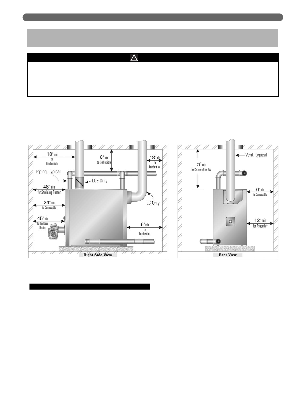
A. ACCESSIBILITY CLEARANCES
1. Clearances for service and from combustible surfaces
are the same for the LCE as for the LC. The
following recommendations allow for reasonable
access to the boiler. Follow local codes and
requirements when setting actual layout. See
Figure 1.1.
a) For installing, removing and servicing the burner:
provide 48" between the front of the boiler and
any adjacent wall or other appliance.
b) For access to the top of the boiler for cleaning
flueways: provide 24" above top of jacket.
c) For accessing and servicing of level controls and
inspection tappings (if used): provide 24"
minimum from the right side of the boiler to any
wall or obstruction.
d) For installation of jacket: provide at least 12"
from the left side of the boiler to any wall or
obstruction. More clearance may be needed for
longer boilers unless the jacket is pre-assembled
before placing the boiler.
e) For installation and removal of tankless heaters:
provide 45" between the end of the boiler and
any adjacent wall of obstruction. [This provides
for all available tankless coils. The spacing can
be closer for Heater Number X-1020 (allow 30")
or Heater Number X-1021 (allow 35")].
The equipment must be installed in accordance with installation requirements of the authority having
jurisdiction or, in the absence of such requirements, to the current edition of the
National Fuel Gas Code
, ANSI
Z223.1/NFPA 54.
Where required by the authority having jurisdiction, the installation must conform to
American Society of
Mechanical Engineers Safety Code for Controls and Safety Devices for Automatically Fired Boilers,
ASME CSD-1.
NOTICE
PREINSTALLATION
1. PREINSTALLATION
Carefully read these instructions before beginning work. Understand all aspects of the installation. Contact your PB Heat’s sales
representative or customer service for help in answering questions.
This boiler must be installed by a qualified contractor. The boiler warranty can be voided if the boiler is not installed, maintained
and serviced correctly.
Figure 1.1: Clearance Requirements
2

B. CLEARANCE FROM COMBUSTIBLE
CONSTRUCTION
Provide the following minimum clearances to
combustible construction. See Figure 1.1.
1. Sides: 6"
2. Rear of Jacket: 6"
3. Front of Jacket: 24"
4. Top of Jacket: 24"
5. Hot Water Pipes: 6"
6. Vent or Chimney Connector: 18"
C. COMBUSTION AND VENTILATION AIR
1. The installation must provide adequate air for
combustion and ventilation.
2. Unless the boiler room construction and natural air
infiltration are sure to provide all the air needed,
provide an opening or duct to the outside with a free
cross sectional area of at least 1 square inch per
4000 Btuh input for all installed appliances. At high
altitude, increase this requirement 4% for each 1000
feet above sea level.
3. The boiler room must never be under negative
pressure. If exhaust fans or other equipment can
cause a negative pressure in the boiler room, the air
openings and equipment design must be engineered
to assure a neutral or slightly positive pressure in the
boiler room at all times of operation. If the
equipment design and air openings cannot assure
this, then the boiler must be located in an isolated
room.
4. Using combustion air dampers:
a) If motorized dampers are used on the
combustion and ventilation air openings, wire
them such that they must open when the boiler
tries to operate. They must include a switch
which prevents the boiler from operating if they
do not open. See Figure 1.2.
D. CHIMNEY OR VENT
1. Inspect the existing chimney or vent system. Make
sure it is in good condition. Inspect chimney liner
and repair or replace if necessary.
2. The vent system and installation must be in
accordance with the current edition of the American
National Standard ANSI/NFPA 211, “Chimneys,
Fireplaces, Vents, and Solid Fuel Burning
Appliances”, or applicable provisions of the local
building codes. The venting requirements for the
LCE are the same as for the LC. Figure 1.3 shows
the top flue outlet required on LCE boilers.
3. Chimney/Vent Operation: The vent system must be
sized and installed to remove all combustion
products. If the vent system is not sized properly, the
burner may not operate properly. This can cause
poor combustion or sooting to occur.
4. If the vent terminates in an area where windgenerated downdrafts are likely, install a suitable vent
cap which can control wind effects.
5. This boiler is designed to fire only with a pressurized
fire box. The breeching and vent may be sized for
negative, neutral or positive pressure (no more than
0.l inches water column at the boiler outlet) as
desired. But negative pressure overfire can cause
lifting of the flame and poor combustion or
overheating of the boiler crown sheet.
6. Forced draft breechings and vents must be sealed
and of heavy gauge steel construction and must
comply with all applicable codes of construction.
7. The vent diameter and minimum height for stub
vents are listed in the Ratings and Dimensions
Section of this manual. Always extend vent
terminations at least 3 feet above the roof line. See
Figure 1.3.
3
PREINSTALLATION
Figure 1.2: Motorized Vent Damper Interlock Figure 1.3: Vent Termination, Typical
Failure to provide adequate venting can result in
severe property damage, personal injury or death.
WARNING

4
8. Exterior Vents:
a) Insulate sufficiently to ensure adequate draft and
to prevent vent damage due to condensation.
9. Vent Connection to Boiler:
a) Support the weight of the vent system
independently of the boiler flue connection.
b) Provide support of the vent connector
(breeching) at maximum 12 foot intervals to
prevent sagging and to provide a minimum
upward slope of 1/4" per foot.
10. Do not vent natural draft appliances in a combined
vent which operates under positive pressure.
11. Draft Regulator: Install a barometric draft regulator
where using high chimney or any high draft vent.
This is needed to prevent causing negative draft in
the boiler. Excess draft will cause flame lifting and
possible impingement.
12. The Draft Damper for the LCE boiler is a separate
piece, shipped in the Top Flue Outlet Carton.
a) Install the Draft Damper as close as possible to
the boiler flue outlet. It can be installed vertically
or horizontally provided that the connecting vent
piping and fittings are designed and installed for
pressurized service.
b) Secure the damper to the vent with screws and
seal the joints with a bead of high temperature
silicone sealant (found in Section Assembly Kits).
c) The vent must be installed so it can be
disconnected and the Top Flue Outlet removed
for proper cleaning of the flueways.
E. BOILER SETTING
1. If the boiler room floor is not level or if additional
structural support is needed, provide a good, level
foundation for the boiler with the minimum
dimensions given in Table 1.1. The flooring and
structural support system must be suitable for the
operating weight of the boiler and any connected
piping. Place the Steel Channels on the foundation
as shown in Figure 1.4.
2. Do not operate the boiler until the foundation, if new
concrete, has thoroughly cured. The concrete might
be damaged if heated too quickly due to the
entrained moisture remaining.
3. If the boiler is installed in a penthouse or if wiring of
any sort is run underneath the boiler foundation,
construct the foundation with provision for air flow
underneath between the main floor and the top of
the boiler foundation.
a) An acceptable foundation would be concrete
blocks laid with the openings lined up.
Do not install this boiler on carpeting or any
combustible flooring. A significant fire hazard could
result, with potential for property damage, personal
injury or death.
WARNING
Figure 1.4: Foundation Layout
PREINSTALLATION

b) If the foundation must be a concrete slab, use an
air cell high temperature insulating board, at least
1/2 inch thick, with aluminum backing,
aluminum side up. 1/2 inch thick high
temperature millboard with aluminum backing is
acceptable as well. Place the insulating board on
the slab between the steel channels.
F. INSTALLATION SURVEY
For new and existing installations, a Water Installation
Survey is available from PB Heat, LLC. The survey will
provide information on how a hot water boiler works
with your specific system and will provide an overview
of hot water system operation in general.
You can also use this survey to locate system problems
which will have to be corrected. To obtain copies of the
Water Installation Survey, contact your PB Heat
representative or download it from PeerlessBoilers.com.
G. PLANNING THE LAYOUT
Prepare sketches and notes of the layout to minimize the
possibility of interferences with new or existing
equipment, piping, venting and wiring.
H. VERIFY COMPONENTS
1. Packaged: All components should be inside crate. In
some cases the burner may be shipped separately.
Optional equipment, such as barometric draft
dampers, may also be shipped separately.
2. Knockdown: All components shipped for field
assembly. See Table 1.2 for standard components.
See Tables 1.3 through 1.8 for optional components.
a) Channel Rails
b) Sections
c) Assembly Kit Carton(s): Includes flow port
gaskets, tie rods with hardware, high temperature
rope, and cleanout cover plates.
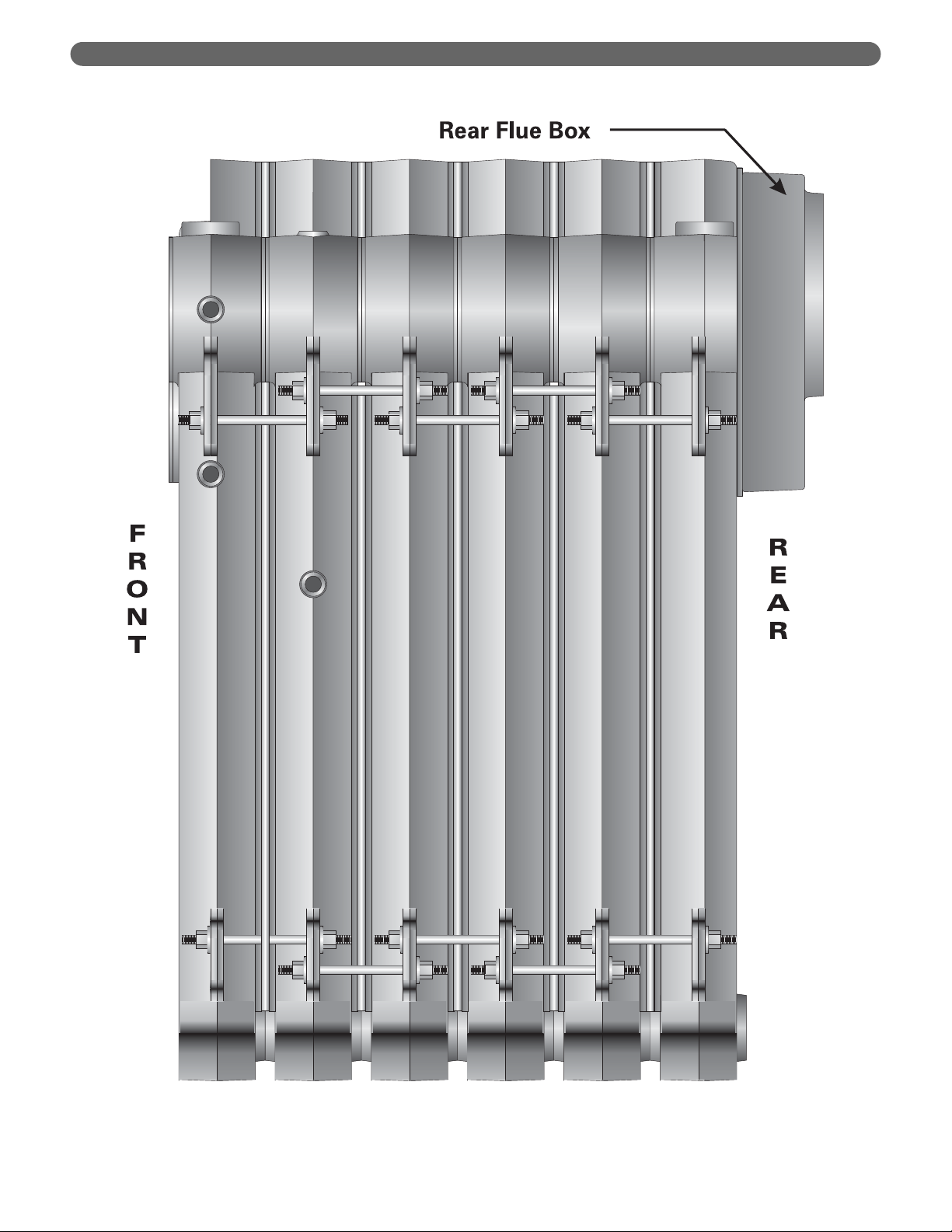
d) Flue Box Carton: Includes flue box, rear flue
cover plate (LCE only), rear observation
assembly and port cover plates.
e) Baffle Carton
i) LC: Includes baffles, combustion chamber
liner and rating label.
ii) LCE-21 through LCE-24: Baffles
f) Jacket Cartons: Include ASME plate
g) Draft Damper (LCE only)
h) Label Carton (LCE only)
i) Burner Mounting Plate
j) Trim Carton: Includes safety relief valve and
temperature-pressure gage
k) Control Carton: Limit controls
l) Tankless Heater(s)
m) Additional controls and fittings
3. Assembled Block: Same as knockdown except
channel rails, sections and assembly kit cartons are
assembled into a block as a single shipping level
component.
5
Table 1.1: Foundation Lengths
LC-04
LC-05
LC-06
LC-07
LC-08
LC-09
LC-10
LC-11
LC-12
LCE-13
LCE-14
LCE-15
LCE-16
LCE-17
LCE-18
LCE-19
LCE-20
LCE-21
LCE-22
LCE-23
LCE-24
Model
Foundation Length, Inches
37¹⁵⁄₁₆
43
48¹⁄₁₆
53¹⁄₈
58⁵⁄₁₆
63³⁄₈
68⁷⁄₁₆
73¹⁄₂
78⁹⁄₁₆
83³⁄₄
88¹³⁄₁₆
93⁷⁄₈
98¹⁵⁄₁₆
104¹⁄₈
109³⁄₁₆
114¹⁄₄
119⁷⁄₁₆
124¹⁄₂
129⁹⁄₁₆
134⁵⁄₈
139¹¹⁄₁₆
PREINSTALLATION

6
PREINSTALLATION
Table 1.2A: Series LC Shipping List
Panels
Top/Side
Hardware
(Tbl 1.4, 1.5 Options)Flue Ctn.
Panels
Front/Rear
Contents
See Below
Contents
See Below
Assembly Kit Ctns. Jacket Cartons
Baffle
3" Tap.
1"
LWCO
Chamber Liner
1
LC-6017
1
LC-6016
Hardware
1
Item 2
LC-5004
Item 1
1
LC-1022
1
LC-1023
Carton
Interm.
1
Interm.
LC-1000-1
A
A
A
LC-04
86031
86030
86040
86050
85004
86005
1
1
1
1
1
1
B
LC-6017-1
LC-6016
A
LC-5004
B
LC-1022-1
LC-05
LC-1023
LC-1000-1
86032
86030
86040
86051
85105
86005
1
1
1
1
1
1
B
LC-6017-1
LC-6016
A
LC-5004
B
LC-1022-1
LC-05
LC-1023-1
LC-1000-1
86032
86030
86040
86051
85005
86005
1
1
1
1
1
1
C
LC-6017-2
LC-6016
B
LC-5004-1
C
LC-1022-2
LC-06
LC-1023-2
LC-1000-1
86033
86030
86041
86052
85006
86005
1
1
1
1
1
1
D
LC-6017-3
LC-6016
B
LC-5004-1
D
LC-1022-3
LC-07
LC-1023-3
LC-1000-1
86034
86030
86041
86053
85007
86005
1
1
1
1
1
1
1
1
1
B
LC-6017-1
A
LC-6017
LC-6016
B
LC-5004-1
B
LC-1022-1
A
LC-1022
LC-08
LC-1023-4
LC-1003
LC-1000-1
86032
86031
86030
86041
86051
86050
85008
86008
86005
2
1
1
2
1
1
1
B
LC-6017-1
LC-6016
C
LC-5004-2
B
LC-1022-1
LC-09
LC-1023-5
LC-1003
LC-1000-1
86032
86030
86042
86051
85009
86008
86005
1
1
1
1
1
1
1
1
1
C
LC-6017-2
B
LC-6017-1
LC-6016
C
LC-5004-2
C
LC-1022-2
B
LC-1022-1
LC-10
LC-1023-6
LC-1003
LC-1000-1
86033
86032
86030
86042
86052
86051
85010
86008
86005
2
1
1
2
1
1
1
C
LC-6017-2
LC-6016
C
LC-5004-2
C
LC-1022-2
LC-11
LC-1023-7
LC-1003
LC-1000-1
86033
86030
86042
86052
85011
86008
86005
1
1
1
1
1
1
1
1
1
D
LC-6017-3
C
LC-6017-2
LC-6016
C
LC-5004-2
D
LC-1022-3
C
LC-1022-2
LC-12
LC-1023-8
LC-1003
LC-1000-1
86034
86033
86030
86042
86053
86052
85012
86008
86005
1
Plain
Interm.
1
Back
Standard Sections (See Table 1.3 for Options)
Channel
Boiler
Front
Rail
Bundle
Model
Number
1
1
Quantity
LC-04
LC-1000
LC-1007
LC-1001
Label
Par t N o.
86004
86022
86000
90160
Stock Code
2
LC-1000
1
LC-1007
1
LC-1001
1
Par t N o.
Quantity
LC-05R
Label
2
86004
1
86022
1
86000
1
90161
Quantity
Stock Code
LC-05
LC-1000
LC-1007
LC-1001
Label
Par t N o.
3
86004
1
86022
1
86000
1
90161
Quantity
Stock Code
LC-06
LC-1000
LC-1007
LC-1001
Label
Par t N o.
4
86004
1
86022
1
86000
1
90162
Quantity
Stock Code
LC-07
LC-1000
LC-1007
LC-1001
Label
Par t N o.
4
86004
1
86022
1
86000
1
90163
Quantity
Stock Code
LC-08
LC-1000
LC-1007
LC-1001
Label
Par t N o.
5
86004
1
86022
1
86000
1
90164
Quantity
Stock Code
LC-09
LC-1000
LC-1007
LC-1001
Label
Par t N o.
6
86004
1
86022
1
86000
1
90165
Quantity
Stock Code
LC-10
LC-1000
LC-1007
LC-1001
Label
Par t N o.
7
86004
1
86022
1
86000
1
90166
Quantity
Stock Code
LC-11
LC-1000
LC-1007
LC-1001
Label
Par t N o.
8
86004
1
86022
1
86000
1
90167
Quantity
Stock Code
LC-12
LC-1000
LC-1007
LC-1001
Label
Par t N o.
86004
86022
86000
90168
Stock Code
1 Assembly Kit Cartons Contents: Flow Port Gaskets, Silicone Sealant, Tie Rods, Washers, Tie Rod Nuts, Section Seal Rope, Spray Adhesive, Cleanout Plates, Mounting Hardware
2 Flue Box Carton Contents: Flue Box, Seal Rope, Observation Assembly, Coil Cover Plates, Cover Plate Gaskets, Mounting Hardware

7
PREINSTALLATION
Table 1.2B: Series LCE Shipping List
1
Label
Rating
1
Draft
Damper
1
1
Panels
Top/Side
Hardware
Chamber Liner
1
1
Panels
Hardware
Front/Rear
1
Item 1
Contents
See Below
1
Assembly Kit Cartons Jacket Cartons (See Table 1.4, 1.5 for Options)Flue Ctn. Lbl. Ctn.
Flow Port Gaskets, Silicone Sealant,
1
Tie Rods, Washers, Tie Rod Nuts, Section Seal Rope,
Spray Adhesive, Cleanout Plates, Mounting Hardware
85013
LCE-8028
A
90523
S-5007-3
E
86094
LCE-6023
B
86032
LCE-6017-1
A
86031
LCE-6017
86030
LCE-6016
D
86043
LCE-5011
E
86054
C
86052
1
LCE-8028-1
1
S-5007-3
1
LCE-6023
2
LCE-6017-1
1
LCE-6016
1
LCE-5011
1
1
1
85014
1
A
90523
1
E
86094
1
1
B
86032
1
86030
1
D
86043
1
1
E
86054
1
D
86053
85015
LCE-8028-2
A
90523
S-5007-3
E
86094
LCE-6023
C
86033
LCE-6017-2
B
86032
LCE-6017-1
86030
LCE-6016
D
86043
LCE-5011
E
86054
B
86051
A
86050
1
1
1
2
1
1
1
2
85016
LCE-8028-3
A
90523
S-5007-3
E
86094
LCE-6023
C
86033
LCE-6017-2
86030
LCE-6016
D
86043
LCE-5011
E
86054
B
86051
1
LCE-8028-4
1
S-5007-3
1
LCE-6023
2
LCE-6017-1
1
LCE-6017
1
LCE-6016
1
LCE-5011
1
1
1
1
85017
1
A
90523
1
E
86094
B
86032
3
A
86031
1
86030
1
D
86043
E
86054
1
C
86052
2
B
86051
85018
LCE-8028-5
B
90524
S-5007-4
E
86094
LCE-6023
B
86032
LCE-6017-1
86030
LCE-6016
E
86044
LCE-5012
E
86054
C
86052
1
1
1
1
2
1
1
1
1
1
85019
LCE-8028-6
B
90524
S-5007-4
E
86094
LCE-6023
C
86033
LCE-6017-2
B
86032
LCE-6017-1
86030
LCE-6016
E
86044
LCE-5012
E
86054
D
86053
C
86052
1
LCE-8028-7
1
S-5007-4
1
LCE-6023
2
LCE-6017-1
2
LCE-6017
1
LCE-6016
1
LCE-5012
1
2
1
85020
1
B
90524
1
E
86094
3
B
86032
1
A
86031
1
86030
1
E
86044
1
1
1
E
86054
1
D
86053
85021
LCE-8028-8
B
90524
S-5007-4
E
86094
LCE-6023
B
86032
LCE-6017-1
A
86031
LCE-6017
86030
LCE-6016
E
86044
LCE-5012
E
86054
D
86053
B
86051
A
86050
1
LCE-8028-9
1
S-5007-4
1
LCE-6023
4
LCE-6017-1
1
LCE-6016
1
LCE-5012
1
1
2
1
85022
1
B
90524
1
E
86094
1
3
B
86032
1
86030
1
E
86044
1
1
E
86054
1
D
86053
1
B
86051
85023
LCE-8028-10
B
90524
S-5007-4
E
86094
LCE-6023
C
86033
LCE-6017-2
B
86032
LCE-6017-1
86030
LCE-6016
E
86044
LCE-5012
E
86054
D
86053
C
86052
B
86051
1
LCE-8028-11
1
S-5007-4
1
LCE-6023
2
LCE-6017-2
2
LCE-6017-1
1
LCE-6016
1
LCE-5012
1
1
2
85024
B
90524
E
86094
C
86033
B
86032
86030
E
86044
E
86054
D
86053
C
86052
Baffle
Carton
1
6
Plain
Interm. Back
1
3" Tap.
Interm.
1
1"
LWCO
Interm.
3
Top
Flue
Interm.
Standard Sections (See Table 1.3 for Options)
1
Front
2
Rail
Bundle
Channel
Quantity
Boiler
Model
Number
LCE-13
LC-1007
LC-1000
LC-1003
LC-1000-1
LCE-1056
LC-1001
Label
Par t No.
1
86022
7
86004
1
86008
1
86005
3
86100
1
86000
2
90162
Quantity
Stock Code
LCE-14
LC-1007
LC-1000
LC-1003
LC-1000-1
LCE-1056
LC-1001
Par t No.
Label
1
86022
8
86004
1
86008
1
86005
3
86100
1
86000
2
90162
Quantity
Stock Code
LCE-15
LC-1007
LC-1000
LC-1003
LC-1000-1
LCE-1056
LC-1001
Label
Par t No.
1
86022
9
86004
1
86008
1
86005
3
86100
1
86000
2
90163
Quantity
Stock Code
LCE-16
LC-1007
LC-1000
LC-1003
LC-1000-1
LCE-1056
LC-1001
Label
Par t No.
1
86022
10
86004
1
86008
1
86005
3
86100
1
86000
2
90163
Quantity
Stock Code
LCE-17
LC-1007
LC-1000
LC-1003
LC-1000-1
LCE-1056
LC-1001
Label
Par t No.
1
86022
11
86004
1
86008
1
86005
3
86100
1
86000
2
90164
Quantity
Stock Code
LCE-18
LC-1007
LC-1000
LC-1003
LC-1000-1
LCE-1056
LC-1001
Label
Par t No.
1
86022
12
86004
1
86008
1
86005
3
86100
1
86000
2
90164
Quantity
Stock Code
LCE-19
LC-1007
LC-1000
LC-1003
LC-1000-1
LCE-1056
LC-1001
Label
Par t No.
1
86022
13
86004
1
86008
1
86005
3
86100
1
86000
2
90165
Quantity
Stock Code
LCE-20
LC-1007
LC-1000
LC-1003
LC-1000-1
LCE-1056
LC-1001
Label
Par t No.
1
1
86022
13
86004
2
86008
1
86005
3
86100
1
86000
2
90165
Quantity
Stock Code
LCE-21
LCE-1074
LC-1007
LC-1000
LC-1003
LC-1000-1
LCE-1056
LC-1001
Label
Par t No.
1
86113
1
86022
14
86004
2
86008
1
86005
3
86100
1
86000
2
90166
Quantity
Stock Code
LCE-22
LCE-1074
LC-1007
LC-1000
LC-1003
LC-1000-1
LCE-1056
LC-1001
Label
Par t No.
1
86113
1
86022
15
86004
2
86008
1
86005
3
86100
1
86000
2
90166
Quantity
Stock Code
LCE-23
LCE-1074
LC-1007
LC-1000
LC-1003
LC-1000-1
LCE-1056
LC-1001
Label
Par t No.
1
86113
1
86022
16
86004
2
86008
1
86005
3
86100
1
86000
2
90167
Quantity
Stock Code
LCE-24
LCE-1074
LC-1007
LC-1000
LC-1003
LC-1000-1
LCE-1056
LC-1001
Label
Par t No.
86113
86022
86004
86008
86005
86100
86000
90167
Stock Code
1 Flue Box Carton Contents: Top Flue Plate, Rear Flue Cover, Seal Rope, Observation Assembly, Coil Cover Plates, Cover Plate, Gaskets, Mounting Hardware
Part #/UPC
Part #/UPC
Part #/UPC
Part #/UPC
Part #/UPC
Part #/UPC
Part #/UPC
8
PREINSTALLATION
Note: 80 psig MAWP not available in Canada.
Note: Boilers with inspection tappings in front and back sections only use
standard cartons.
Table 1.5: Standard and Optional Jacket Cartons,
Top/Side Panels
Front
Plain Interm.
Top Flue Interm.
LWCO Interm.
3" Tap. Interm.
Closed Back
Coil Back
Sections
50 psig MAWP 80 psig MAWP
w/Inspection Tappings
Standard
No Inspection Tappings
No Inspection Tappings w/Inspection Tappings
LC-1001
LC-1000
LCE-1056
LC-1000-1
LC-1003
LC-1007
LC-1002
86000
86004
86100
86005
86008
86022
86036
LC-1013
LC-1014
LCE-1064
LC-1014-2
LC-1015
LC-1016
LC-1017
86010
86014
86110
86092
86016
86018
86026
LC-1001-2
LC-1000-2
LCE-1056-1
LC-1000-3
LC-1003-2
LC-1007-2
LC-1002-2
86002
86006
86111
86007
86009
86024
86038
LC-1013-2
LC-1014-1
LCE-1064-1
LC-1014-3
LC-1015-1
LC-1016-2
LC-1017-2
86012
86015
86112
86093
86017
86020
86028
Table 1.6A: Burner Mounting Plates
Model
CF-800
CF-1400
CF-2300
301CRD
702CRD
801CRD
S4.2
R6.2
R6.3
R8.1
R8.2
R8.3
C1
C2
J15A
J30A
J50A
JB1
Boiler Model
86070*
86070*
86070*
86071
86072
86071
LC-04
86070*
86070*
86070*
86071
86072
86071
LC-05R
86069*
86069*
86078
86071
86072
86071
LC-05
86069*
86069*
86078
86071
86072
86071
LC-06
86069*
86069*
86079
86071
86072
86071
LC-07
86074*
86069*
86079
86076
86077
86075
LC-08
86074*
86073
86079
86076
86077
86075
LC-09
86074*
86073
86079
86076
86077
86075
LC-10
86074*
86073
86079
86076
86077
86075
LC-11
86074*
86073
86079
86076
86075
LC-12
Beckett
Carlin
Gordon
Piatt
Power
Flame
Webster
* Standard Burner Mounting Plate
Standard 50
psig MAWP
86030
30 psig MAWP 86059
80 psig MAWP 86058
Table 1.4: Standard and Optional Jacket
Cartons, Front/Back Panels
Jacket Label
Standard
(No Inspection
Tappings)
With Inspection
Tappings
A 86031 86101
B 86032 86102
C 86033 86103
D 86034 86104
E 86094 86097
Table 1.3: Standard and Optional Sections for Knockdown Boilers

9
PREINSTALLATION
Table 1.8: Control Cartons
Table 1.7: Trim Cartons
LC-04
LC-05R
LC-05
LC-06
LC-07
LC-08
LC-09
LC-10
LC-11
LC-12
LCE-13
LCE-14
LCE-15
LCE-16
LCE-17
LCE-18
LCE-19
LCE-20
LCE-21
LCE-22
LCE-23
LCE-24
Model
87030
87030
87030
87030
87031
87031
87032
87032
87032
87032
87032
87033
87033
87033
87033
87033
87034
87034
87034
87034
87034
87034
Output
1
30 psig
87050
87050
87050
87050
87050
87050
87051
87051
87051
87051
87052
87052
87052
87052
87052
87052
87052
87053
87053
87053
87053
87053
50 psig
87080
87080
87080
87080
87080
87080
87080
87081
87081
87081
87081
87081
87082
87082
87082
87082
87082
87802
87082
87082
87082
87082
80 psig
1 Safety Relief Valve selection based on capacity determined by boiler
output (Gross I=B=R Output). Applies to most locations in United
States and Canada.
Table 1.6B: Burner Mounting Plates
Model
CF2300AKG
CF2300AKB
CF2500
CF3500AKM
CF3500AKL
801CRD
1050FFD
1150FFD
R10.9
R10
R10.1
R10.2
C2
C3
JB2
Boiler Model
86074*
86073
86088
86076
86081
LCE-13
86083*
86073
86088
86076
86081
LCE-14
86083*
86086
86088
86076
86081
LCE-15
86074*
86086
86088
86080
86081
LCE-16
86074*
86087
86088
86080
86081
LCE-17
86083*
86087
86088
86080
86081
LCE-18
86083*
86087
86088
86080
86081
LCE-19
86083*
86087
86088
86080
86081
LCE-20
86080*
86087
86088
86080
86081
LCE-21
86080*
86087
86088
86080
86081
LCE-22
86087
86088
86080
86081
LCE-23
N/A
86088
86080
86081
LCE-24
Beckett
Carlin
Gordon
Piatt
Power
Flame
Webster
* Standard Burner Mounting Plate
Not
Available
LC-04
Through
LCE-24
Model
Water
88510
A. PACKAGED BOILER
1. Remove crate top and sides. Remove any loose
cartons. Remove burner support pedestal and
nipple, if supplied
2. Lift boiler off crate pallet. Move to location
determined in Chapter 1: Preinstallation.
3. Remove lifting frame and hardware.
4. Re-install burner support pedestal and nipple if
necessary.
5. Proceed to Chapter 3: Piping the Boiler.
B. ASSEMBLED BLOCK BOILER
1. Move block to location determined in Chapter 1:
Preinstallation.
2. Remove lifting frame and hardware.
3. Proceed to Section D: Install Coils or Plates
C. KNOCKDOWN BOILER
1. Place channel rails as shown in Figure 1.4.
2. Open the Section Assembly Kit cartons. These
cartons contain the parts needed for assembly of the
sections.
3. Place the Back Section on the floor as shown in
Figure 2.1.
4. The Back Section combustion chamber area is lined
with a ceramic fiber blanket liner. Make sure the liner
is in good condition. Minor tears are not a problem,
but there should be no holes in the insulation.
10
PLACE THE BOILER
2. PLACE THE BOILER
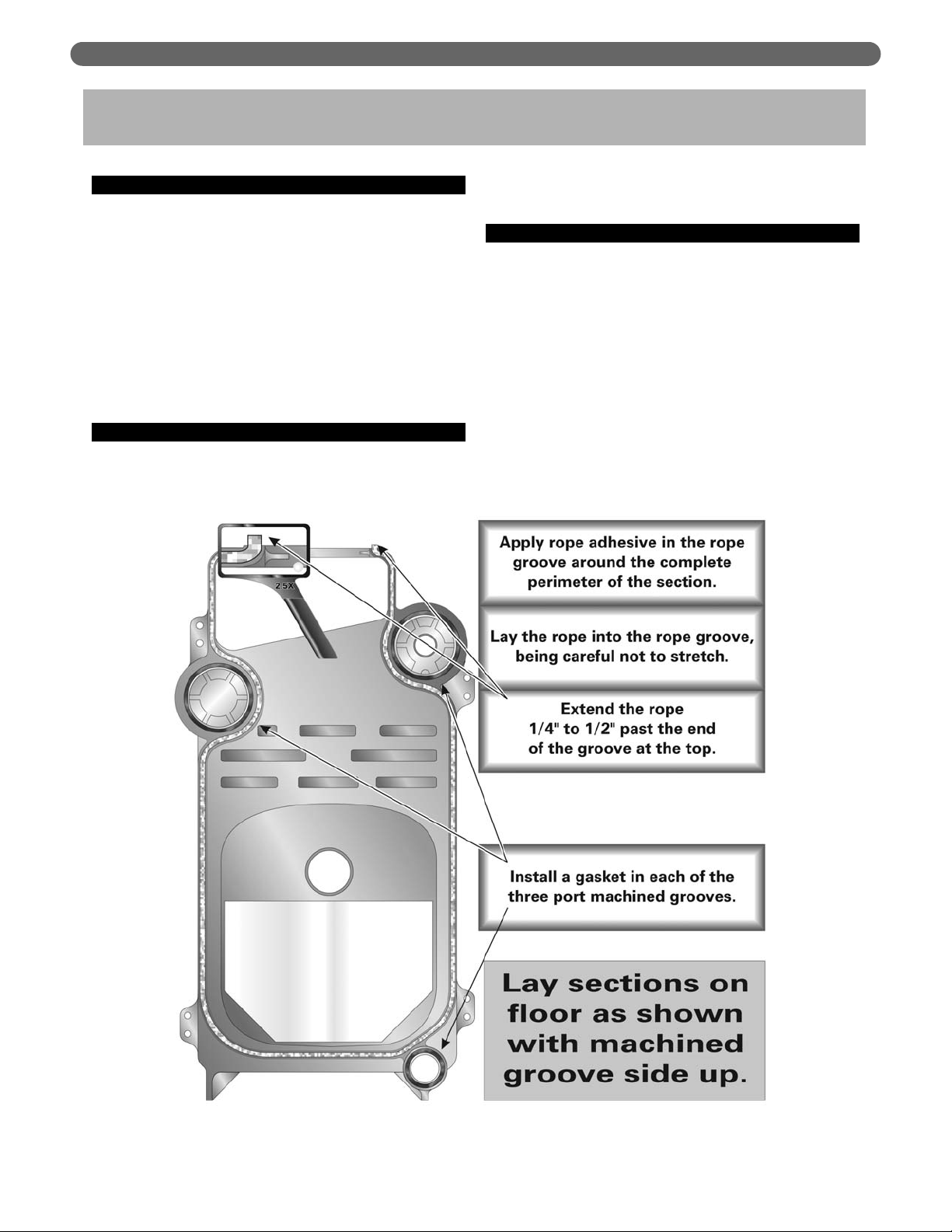
Figure 2.1: Lay Sections on Floor and Apply Rope Seal and Gaskets
5. Clean the area around the flow ports and in the seal
recess. Use solvent and a clean cloth to thoroughly
clean all of the sealing surfaces. Remove all foreign
matter to assure a water tight seal when the sections
are drawn together.
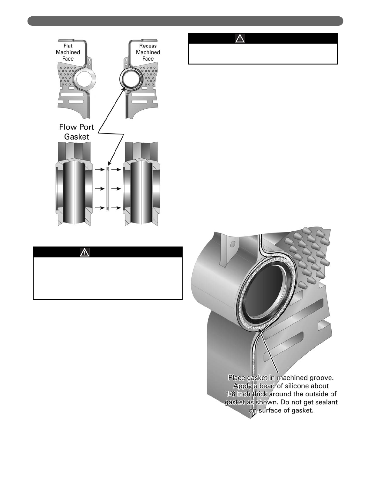
6. Place a Flow Port Gasket in each of the three flow
port recesses as shown in Figures 2.1 and 2.2.
7. Apply spray adhesive in the rope groove around the
perimeter of the section.
8. Place the sealing rope completely around the rope
groove, being careful not to stretch the rope. Extend
the rope from 1/4" to 1/2" past the end of the groove
on both sides of the cleanout opening on top of the
section. This will assure a gas tight seal when the
cleanout cover plate is applied.
9. Apply a bead of silicone sealant around each flow
port as shown in Figure 2.3. Do not get sealant on
the flow port gaskets.
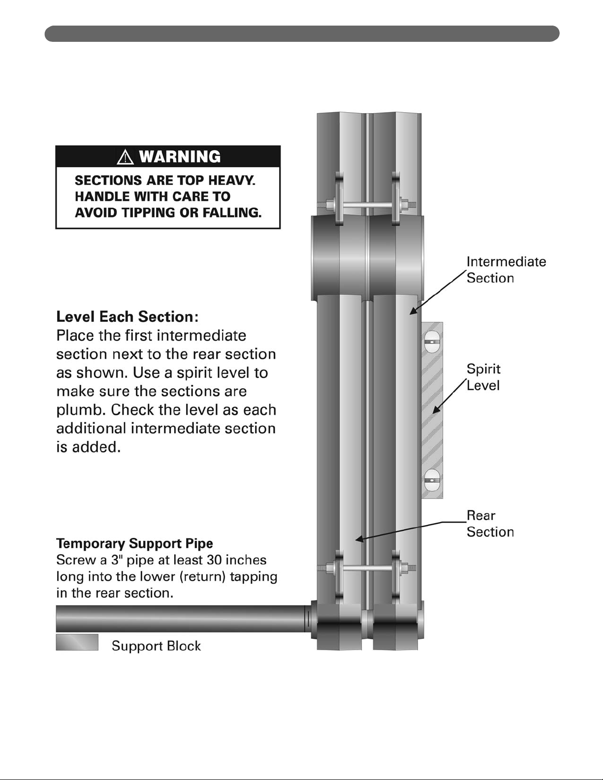
10. Lift up the Rear Section and move into position on
the steel channels on the boiler foundation.
11. Screw a 3" pipe at least 30 inches long into the
lower 3" tapping on the back of the Rear Section as
shown in Figure 2.4. Place a block under the pipe as
shown in the figure and use as a brace during
assembly.
12. Place a Plain Intermediate Section on the floor and
prepare as above.
13. Carefully place the Intermediate Section against the
Rear Section and visually line up the flow ports as
close as possible.
14. Insert a tie rod with one nut and washer applied
into each of the four tie rod lugs. See Figures 2.5
and 2.6.
15. Place the nut and washer on the other end of the tie
rod and draw finger tight.
11
PLACE THE BOILER
Figure 2.3: Apply Silcone Sealant
Gaskets will be damaged by petroleum or its
derivatives. Completely remove all solvent residue
before placing gaskets.
Do not use petroleum based compounds in the
boiler.
CAUTION
Figure 2.2: Flow Port Machining & Gasket
The sections are heavy and must be supported
securely.
WARNING
12
PLACE THE BOILER
Figure 2.4: Install Additional Sections. Use level on each section as tie rod bolts are drawn up.
13
PLACE THE BOILER
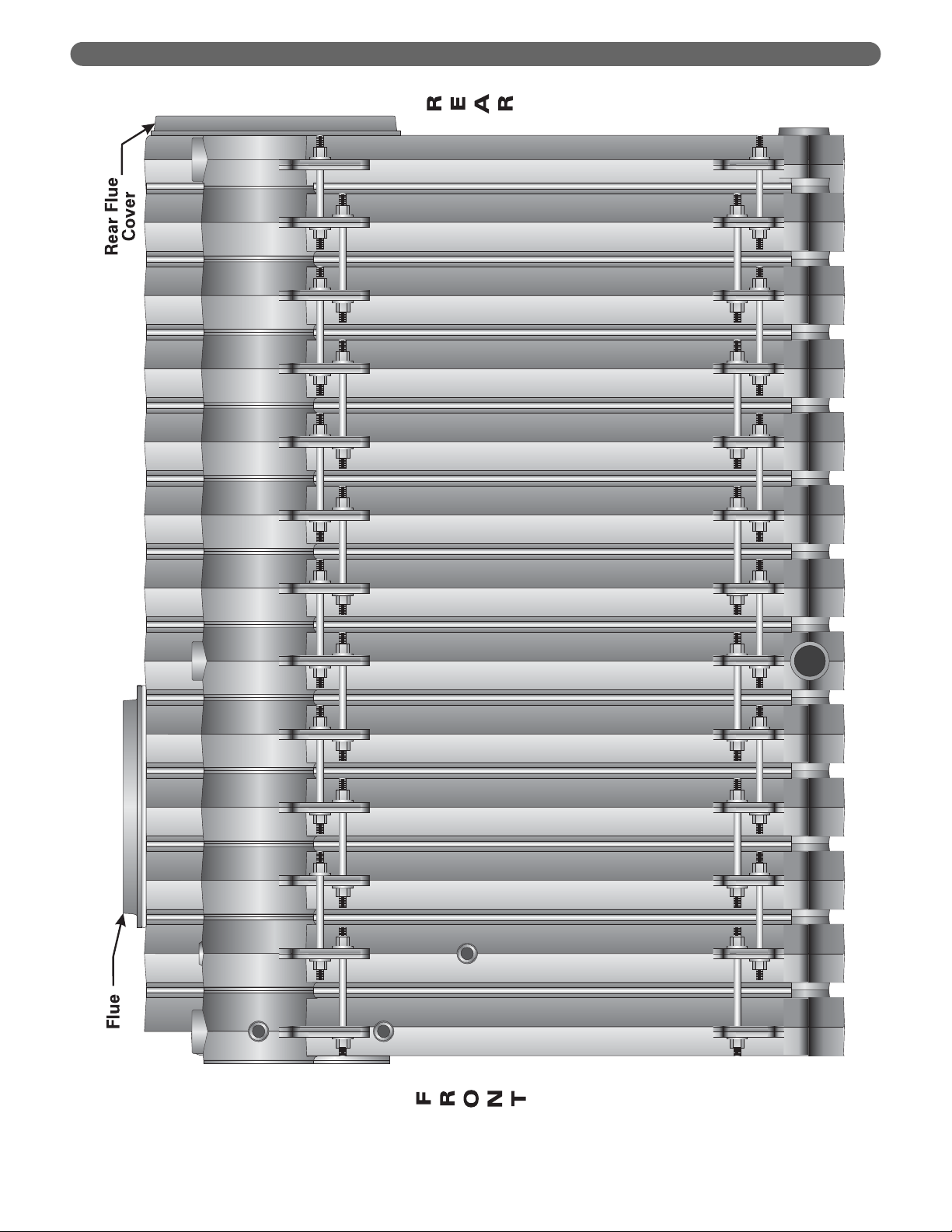
Figure 2.5: Series LC Boiler Assembly – Right Side View
14
PLACE THE BOILER
Figure 2.6: Series LCE Boiler Assembly – Right Side View
16. To properly assemble LC/LCE sections in the field,
the following steps must be followed to ensure that
no damage occurs to the tie rod lugs. A 0-100 ft-lbs
torque wrench is required.
a. Use a spirit level as shown in Figure 2.4 to check
the alignment of the sections as the nuts are
drawn up. Keep the sections plumb.
b. Draw the sections together evenly, in three
rotations. Torque each port to 20 ft-lbs for the
first rotation, then to 40 ft-lbs for the second
rotation, then to 60 ft-lbs for the third rotation.
Use the following sequence until all three ports
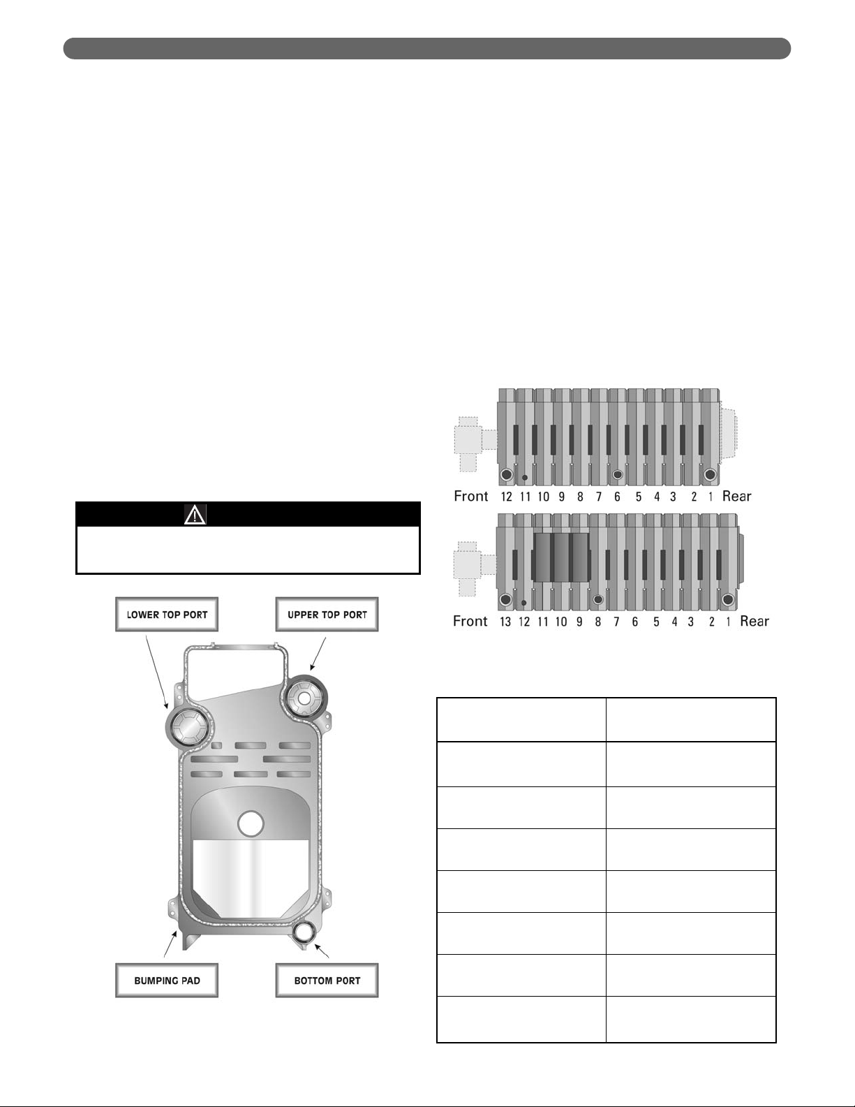
touch metal-to-metal at 60 ft-lbs. See Figure 2.7
for port reference.
i) First: Lower Top Port
ii) Second: Bottom Port
iii) Third: Upper Top Port
c. Tighten these (3) three locations only to a torque
value of 60 ft-lbs. DO NOT EXCEED.
d. After the three ports have been tightened to 60
ft-lbs, tighten the draw rod at the bumping pads
until metal-to-metal contact is reached. This will
assure a proper gas tight seal and prevent the
products of combustion from migrating into the
boiler room.
17. Repeat with the remaining sections.
a. Save the LWCO Intermediate with two 1"
tappings (for level control) for use as the section
closest to the front section.
b. Place the Intermediate Section with 3" top
tapping (Tapped Intermediate) in the position
given in Figure 2.9.
c. LCE ONLY. Save the (3) Top Flue Outlet
Intermediates (with wide opening in top of the
flue collector) for use as the sections closest to
the LWCO Intermediate Section. See Figure 2.9.
i) The sequence from Front to Rear is:
• Front Section
• 1" Low Water Cut-off Intermediate
• Three (3) Top Flue Outlet Intermediates
ii) The remaining intermediate sections are 3"
Tapped Intermediates or Plain Intermediates
as shown in Figure 2.8 and Figure 2.9.
15
Do not exceed the manufacturer’s torque
recommendations.
WARNING
PLACE THE BOILER
Figure 2.7: Torque Specification/Procedure
Figure 2.8: Section Positioning Numbering
Table 2.1: Section Numbering Sequence
LC-04
LC-05
LC-06
LC-07
LC-08
LC-09
LC-10
LC-11
LC-12
LCE-13
LCE-14
LCE-15
LCE-16
LCE-17
LCE-18
LCE-19
LCE-20
LCE-21
LCE-22
LCE-23
LCE-24
Model
Place a Tapped Intermediate
Section at Position
(Numbered Rear to Front)
NA
NA
NA
NA
4
5
5
6
6
8
9
10
11
9
9
9
9
9, 16
9, 17
10, 18
10, 19
 Loading...